A DIY Theodolite for Measuring the Dip of the Horizon

You should be able to check that to a reasonable degree of accuracy by going to a local spot height as marked on the Ordnance Survey map and comparing what your GPS says, taking a few readings to average it.

This is a useful link for looking at the large-scale maps http://www.geograph.org.uk/showmap.php?gridref=SN580810

Or this shows heights to 0.1 metres in your area: http://map.ceredigion.gov.uk/connect/?mapcfg=PLANNING_APPLICATIONS

Many thanks. I think I was close enough. I'll PM you a photo so that you can work out the height of Ladder Wall above the water..
Here is the tide: http://www.ukho.gov.uk/easytide/easytide/ShowPrediction.aspx?PortID=0488&PredictionLength=1
 
I have another cunning plan. Mount a 'red dot finder' on top of a pendulum or electronic gyro mount, like RCT junior. Although it would have to be set at sea level, I could make a continuous video of driving down a hill, overlooking the sea, so the adjustment could not be fiddled with. It would look like this: (vis + IR}pendulum cam.jpg
 
Last edited:
While looking at the history of surveying I wondered if there were other ways of making a DIY line-of-sight theodolite like mine. After all a 4' level is a bit large to tote around.

One alternative to a spirit level is a water level, basically a tube filled with water, with a container at each end allowing you to see the water height (although at the simplest you could just use a section of clear plastic tubing.
640px-Schlauchwaage_Schematik.svg.png
I managed cock this method up, so it is not fool proof, Guess how.
The line between the two is then essentially level (technically it's level at the midpoint, but for practical purposes it's level at either end.)

So you might be able to make a more compact sighting level using a water level. The visual evidence of "level" might be more compelling than using the spirit/bubble level, as you would be able to see the water level and the horizon in the same image. You might even be able to use a relatively short section of pipe with some vertical transparent bits that you could hold in front of an iPhone to, at the least, demonstrate the ocean horizon falls below level.

Perhaps a trip to Home Depot is in order.....
http://www.homedepot.com/p/Sioux-Ch...-D-x-2-ft-Clear-Vinyl-Tubing-HSVUR2/204407882
20170426-095230-qxrac.jpg
 
Last edited by a moderator:
Here's a video of someone using the liquid level at various elevations (sea level, 1200 feet, and 5600 feet):


On the plus side, it shows exactly what we would expect - that the level of the liquid is somewhat higher than the horizon:

horizon level liquid test.jpg

On the negative, he neither used a tripod for the camera, nor a stable base/frame for his level.
 
I was thinking about this design to create a scale for fine degrees.
Protractorv4.jpg
Basically its a perfectly straight wooden plank with a protractor glued to the bottom. Roll up some thin strip of paper till its diameter fits 10 degrees at the top of the protractor. Measure and note down the distance (d).

At twice that distance, the angle of view would be halved. So, at 2d, it will be 5 degrees.
At 4d 2.5 degrees, at 8d 1.25 degrees, and at 16d 0.625 degrees. Etc.

Glue the rolled up paper strip at the desired distance to make it measure your angle.
For instance, if you want 0.5 degrees, you can calculate the amount of d's you need for that. (its ehm.. its.. ehm.. )

Also glue one at the very beginning. Look thru it to measure the angle: all of it visible inside with space to spare: the arc length is below the angle measured. Some of the object visible outside the visor: arc is larger. Object fits visor: object is about same arc as the angle measured.

Perfect for moon watching. Attach welders glass in front, and measure suns arc length.

Yes, the error would be 'large', but not HUGE. And it would show that the size stays the same during a 24 h day. Which is the whole point.
 
On the negative, he neither used a tripod for the camera, nor a stable base/frame for his level.

What he did is sufficient though. The rig uses large tubes, which is a great idea as it stabilizes the water level much quicker than the thin tube. The base is rock, and while he wobbles it around a bit, you can see it's pretty consistent. I'd declare this a win!
 
I have written some code that outputs this:
output01.png
You can pretty easy use it if you have some tube lying around: just measure the inside diameter, put in the desired degrees to measure, and it will tell you how long the apparatus should be. Also can tell you where to put the scale lines for the degrees.
Here is the explanation for the math, and the general design:
Protractorv5.jpg
This could be one side of a wooden plank, the water level on the other side of it, calibrated to the top of the inner tube. Or without the water level to watch sun or moon.

Put it on a 360 degree foot with 2 small water levels (for horizontal x and y axis), a compass, make it turn 360 vertical, and you have a decent DIY theodolite.

I also included the python code (rename .txt to .py).
If anyone spots a problem, please tell.
 

Attachments

  • theodoliteV1.txt
    2.6 KB · Views: 640
Last edited:
This is a great idea.

I had a different idea, which is to sight opposite horizons at the same time. If as FEers say "the horizon rises to eye level" it should be possible to sight at opposite horizons with a single straight line.
I'm waiting until the next time I fly somewhere to try this out. All it takes is daylight, a good high altitude, and something straight, like the edge of a piece of paper:

upload_2017-8-31_21-11-28.png
 

Attachments

  • upload_2017-8-31_20-55-38.png
    upload_2017-8-31_20-55-38.png
    20.5 KB · Views: 1,091
Last edited:
Yes, sighting both horizons at once could be interesting. I had thought of doing it with a device called a "line ranger", as seen on page 8 of "Principles and Use of Surveying Instruments" Third Edition 1969. A line ranger is just two mirrors at a 90deg angle so that you can see two opposite directions at once, perpendicular to your line of sight, so that you can see if you are exactly on a straight line between two points. I had thought that flat earth investigators could even make their own very cheaply and simply, and even calibrate it themselves, so they could verify themselves that it was accurate. But then I realized that it would be hard to find a place near the coast of California that I could view the ocean from a high mountain with ocean in both directions 180deg apart. Plus I realized that even a relatively simple construction project could be a significant obstacle. I couldn't readily find suppliers for these line rangers. Probably because of the insufficiently specific search words "line" and "ranger", and because surveyors probably use them less in todays world of GPS surveying.

Then I realized that a tube level might work well. I'm clearly not the first to think of that. One small obstacle there is getting the clear tubing. A solution could be to use a garden hose. A garden hose would allow a nice long baseline for very precise leveling. Unfortunately it doesn't make for easy photography of the water surfaces with the horizon. I was thinking of just filling the hose completely to each end. One issue there is that the hoses all seem to have a loose metal thread ring on the female end that might leak if filled all the way. But it seems workable, and probably nearly all flat earth investigators have, or could borrow, a hose. I was thinking of sticking a couple short pieces of clear tubing into the ends of the garden hose, but who would happen to have pieces of just the right size? Maybe we could improvise some clear end pieces, like say by wrapping some clear packing tape around the ends of the hose, or hot gluing some water bottles to the ends.

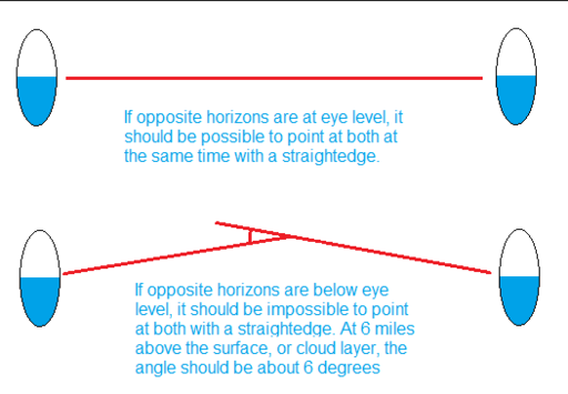
Viewing out opposite windows of an airliner would be great. The altitude would give a large angle. There are a couple issues I can see. One is that it may be hard to keep the straight edge level between viewing from one side and the next. One solution to that might be to set up two cameras, one at each end facing opposite directions. Then you could edit the two videos or pictures together to show a simultaneous view and reduce the doubts that flat earthers might have about the stability of the straight edge. Each camera would tend to block the view of the other, so you might have to set each up along two different parallel straight edges, and make calibration images before and after. Another possibility might be to put a camera at one end of the straight edge, and a mirror next to the other end.

Another tougher problem might be that the flat earthers might blame the horizon droop angle on refraction through the tilted/curved airline windows.

@Bas Koning - Your device looks like it might be interesting, but the blue graph paper image is a little too blurry for me to make out what's shown, even when I enlarge it. As far as graduating an angle measuring device is concerned, one trick is to use a linear scale, such as a centimeter ruler or tape. For example, if you mount a couple centimeters of a centimeter ruler, 57.3cm away from the location of the eye, then for small angles, the centimeters will represent full degrees and the millimeters will represent 1/10 of a degree, or 6 minutes of angle. Another idea for measuring angles with a little accuracy over a wider range, is the CD jewel case sextant like this:
http://www.tecepe.com.br/nav/CDSextantProject.htm
Unfortunately I would say it's not usable to look at the sun without a proper professional sun shade, not a homemade one. But that still leaves a lot of other things one can measure. The cool thing about sextants is that you can do accurate angle measurements just hand held, without a stable mount, because both images of the two objects being viewed move together when you wobble the sextant.

@Everyone - A great time to catch these tube level images would be at sunrise/sunset or moonrise/moonset, so that the actual horizon level could be more accurately seen, and also so that a sense of scale for the droop angle would be in the frame. Unfortunately ,it usually gets foggy by sunset around here. Also, the sun cuts through horizon haze better, but it creates camera exposure and possible eye damage complications. Remember, even if the haze has cut the visible sun brightness to a comfortable level, that may not mean that the invisible longer infrared and shorter ultraviolet wavelengths may not still be getting through at dangerous levels. You can't feel the burn from the invisible wavelengths. And just because you or others have looked at it before doesn't mean that it didn't or won't cause just a little eye damage, like maybe slightly degrading your night vision or something that you don't immediately notice. I would however be willing to risk my low end camera sensor pointing at a dim sun near the horizon. For photographing the full brightness sun, I cut a pair of polycarbonate sun glasses up into seven pieces to stack in front of my camera lens. At first I thought that would be tolerably good for naked eye viewing as well, then I realized that although the polycarbonate might block all the UV, the pigments might not block the long infrared wavelengths well at all.
 
I've created a spreadsheet dealing with calculations associated with the FE conflict.
20171001-082813-98zf5.jpg
Source: https://docs.google.com/spreadsheets/d/e/2PACX-1vQpZV2GFHdJ2EHKxCDq-6gvROUlgzsl9TdkEUCHhnI2iZgwqi-J8FQBEcZYHYLh5a38EzhbnRX7cxf4/pubhtml


Now I wanted to know what the angle of declination was per unit height and also the drop of the earth as one moved from a location.

Now I've arrived at a few conclusions.

1. At the average airline cruising altitude of around 11 kilometres there is a declination of around three degrees. Not enough for the average observe to detect without some kind of instrument such as a theodolite.

2. FE'rs are wasting their time with height altitude experiments because once again even if you reach an altitude of 22km the declination to the horizon is still only going to be about five degrees and will not be noticeable to the casual observer.

3. The international space station should see a declination to the horizon of about twenty degrees. By now it should be definitely noticeable.

I've put the formulas I used at the top of each column.

Have at it folks. Feel free to check my formulas and see if there's any errors. They will be easy enough to fix.
 
Last edited by a moderator:
DIY Theodolite.jpg

A theodolite is a relatively simple instrument for measuring vertical and horizontal angles. It's commonly used for surveying, but you can also use one to get a rough estimate of the curvature of the Earth by measuring how far the horizon falls below eye level from different altitudes.

Modern theodolites are now often digital and expensive, but the classic theodolite still works quite well for this purpose. A classic theodolite, like the Würdemann model seen above, consists of an adjustable base that you set to level with adjustment screws and spirit levels. You then use a telescope with a crosshair to sight the distant object (the horizon in our case) and then read off the angle of the telescope for the circular scale.

You can then measure the dip of the ocean horizon from various altitudes. While there's issues of visibility from waves (at very low altitudes) and haze (at higher altitudes), you should be able to get a good range of readings.

It struck me that while this is a great practical experiment to measure the curvature of the Earth (or simply to demonstrate that there is a curvature, for the Flat Earth folk) not many people have a theodolite.

So I decided to try making a very simple "theodolite", which is basically a cheap 48 inch spirit level with a bit of cardboard stuck on the end. You rest this on something and adjust it so it is level. You then look along the top edge and see where the ocean horizon is relative to that. If the earth were flat then the ocean horizon would be in line with the top edge. Since it's not, we see the horizon dip below the top edge, and dip more as we get higher - indicating the ocean surface is curved.

For the very simplest experiment - demonstrating that there's a curve - we don't even need to use the bit of cardboard (although it's still helpful). All you have to do is set the level so it's level, and then look along it. If the horizon is below level then you have demonstrated the curvature of the ocean.
20170420-115219-xu99z.jpg
(I'm using a tripod here, but that's just for convenience, you can just put it on a wall or some other object, and adjust it to level by putting things underneath it.)


See also:
In the picture of your 48" level above, it's a good idea to include a verification of its calibration, which is easily accomplished by reversing the level such that the spirit vial is turned end-for-end, and replacing the level on the same supports as shown here. If the vial was correct reading "level" then once it's reversed, it will still read "level" as it does here. However, if after reversing the vial/level the second reading shows "not level," then your vial is out of calibration, and that must be compensated or corrected.

Some levels have screws you can loosen to adjust the vials, and many of these don't work very well. To be sure, you ought to become familiar with the technique of marking your vial window with a sharpie or some such marker or paint, which marks will accurately show where the bubble ought to be when the vial is truly level. You find this place by reversing the vial repeatedly and making pencil lines on removable painter's tape which you have stuck to the window parallel with the vial. Once you have found the two limits of the bubble that define where it is in fact level -- because the bubble always settles there when you reverse the vial/level and reverse it again -- then you have the pencil marks that tell you where to put the sharpie lines. You're effectively REPLACING the manufacturer's black lines on the vial with CORRECTED black lines. (I say "effectively" because you probably have to leave the original lines and paint the new ones in the correct place, remembering to IGNORE the original black lines when you use the level.)

Once you know for certain that your level is calibrated and correct, then you can go ahead with whatever work you were going to do with it.

Using the plastic tube filled with colored liquid method, it calibrates itself automatically and you don't have to fool around with fixing it.

Incidentally, this is precisely the same process that is used in the old school theodolite set-up or dumpy level on a tripod. They used to have 4 leveling screws (now modern ones have just 3 and you use a slightly different technique). To level the scope, you secure it at 0 deg. horizontal, with the scope directly parallel with 2 of the screws, which screws you turn up and/or down until the scope vial reads level. This is phase #1. Then YOU REVERSE THE SCOPE end-for-end which reverses the vial as well, and check to be sure the vial still reads level. If it does not, then you have to do as I described above, and repeatedly adjust, reverse the vial, adjust, reverse the vial, adjust .... as many times as it takes until the spirit bubble reads THE SAME in both directions. That is, if the bubble touches the black line on the LEFT, then after you reverse it the bubble must still touch the same black line but this time it will be the black line on the RIGHT. Phase #2: After you finish with those two screws then you move to the other two, setting the scope at 90 deg. to the first phase, and repeat the whole process. This is likely the procedure necessary to set up the old time brass theodolite you show in the top image above. This process takes at least 2 or 3 minutes, sometimes can take 5 minutes, but if longer than that you need to practice and get your speed up!

With modern theodolites, they are usually self-leveling and all you gotta do is get a tiny round bubble to be somewhere inside a little black circle using the 3 leveling screws, which takes about 15 seconds once you get to know the ropes. Incidentally, the self-leveling mechanism inside these nifty (and expensive!) rigs does something not too unlike your "Horizon Cam" above. It uses a prism suspended by tiny strings which dangle like an internal plumb bob in a liquid-filled vial, or something similar. The prism reflects the image like prisms in binoculars do. It's very clever.
 
I like the water filled tube best, but even that can go wrong as my conservatory roof could testify. The tube needs to be quite large in diameter and a constant temperature, with small vertical extent. If you use a long length of small bore tube, filled with alcohol, and let it dangle you can get the wrong result, but at least if you bring the ends together you know when you have ****** **.


While certainly interesting, this isn't even close to being accurate. Your level isn't even level, the bubble isn't centered within the two lines, and even if it were a four foot level isn't made for the kind of accuracy one would need for measuring the dip/drop of the horizon.

Even 1/16th of an inch out of level in a four footer will show the bubble centered.

I, being a bricklayer have used levels all my life. They aren't all that accurate. Good enough for construction, but not for this.

The water level would be the most accurate imo, like the one you posted in another thread where they went 1000 meters.


Source: https://m.youtube.com/watch?v=4uwvx7-x98U
 
While certainly interesting, this isn't even close to being accurate. Your level isn't even level, the bubble isn't centered within the two lines, and even if it were a four foot level isn't made for the kind of accuracy one would need for measuring the dip/drop of the horizon.

Not very accurate, but a lot more practical than 1000m of tubing. The idea is to give a rough demonstration of the dip of the horizon from different altitudes.

I think though you can probably get it within 0.1° with this simple method. If accuracy is what you are looking for then go for an actual self-leveling surveying instrument.


Honestly I don't really know how accurate the most sophisticated self-leveling instrument is.

I have a construction laser-level, but at 100ft it's only accurate +- 1/4 inch.

I wasn't trying to put down your experiment, just saying a four foot level is not very accurate for this type of thing.

I'm not even sure about how accurate a theodolite would be at long distances.
 
Yeah, but we're just measuring angles here, not height.

Understood, and I can see how a theodolite is accurate enough for surveying because it's not being used at a great distance.

In order to measure the angle of the horizon the level line would have to be perfectly level wouldn't it? Even 1/16 of an inch off in 100ft would cause a big error in 3 miles or further.

Again, interesting experiment, and one useful to gain a general idea, but again not accurate enough as proof imo.
 
The angular error remains the same. 1/16th of an inch in 100ft is an angular error of 0.003° No matter what the distance is, the error in the angle remains the same.

Using a theodolite to measure the angle from ones position to two fixed objects should be pretty accurate. After all you have three fixed points.

But to measure the angle of a supposedly level line and the horizon can only be accurate if you know that your "level" line is perfectly accurate.

Is it even possible to project a perfectly level line 1000ft, let alone three miles or more?

To be honest, I don't know.
 
But to measure the angle of a supposedly level line and the horizon can only be accurate if you know that your "level" line is perfectly accurate.
But if your level line is within 0.1° of level then that's the most the error is going to be.
 
Here's a video of someone using the liquid level at various elevations (sea level, 1200 feet, and 5600 feet):


On the plus side, it shows exactly what we would expect - that the level of the liquid is somewhat higher than the horizon:

horizon level liquid test.jpg

On the negative, he neither used a tripod for the camera, nor a stable base/frame for his level.

This guy in Malibu and Mt. Wilson did an excellent job. He provides elevation, location, latitude and longitude. Now all we need is the time of day, the date, temperature and humidity! :)

This is a great idea and his apparatus is very convincing. I'd like to see it wiggled a bit to see the water levels teeter-tottering and then settling down to stable, that would be impressive too.

He could have improved it by using a tripod and also there should be several different shots from Mt. Wilson, from different positions and using different bearings (directions) to nail this thing down. Ideally, several photos over a longer time span separated by hours would be helpful to reinforce the credibility, because of a variety of lighting conditions. I appreciate the very good position of his plastic tubes he used so you can see both of them AND the horizon at the same time. Very well done!
 
Last edited:
But if your level line is within 0.1° of level then that's the most the error is going to be.
I like to see you sticking to your guns, Mick. The error reduced to a fraction of a degree is definitive. Tradesmen in the USA generally work in fractions of an inch, though. Conversion to degrees is logical and scientific, but not customary in the trades.

As for spirit levels, I have an 8-foot level, standard American lumber yard hardware store issue, that is quite sensitive and reliable. Whether checking level or plumb, I can see accuracy to within 15 thousandths of an inch (+/- 0.015") in 8 feet. A 0.015 feeler gauge's presence at one end is detectable. That means +/- 0.008" in 4 feet, or +/- 1/128" per 4'. In my experience levels designed for masonry use have smaller bubbles and more room between the vial limit lines, perhaps because in use they get scratched by the grit in mortar or during clean-up and a finer-tuned vial would get harder to read.

Therefore it's not out of line to say a 4' MASONRY level with 1/16" error can still read level. But with a good carpenter's level, that's not the case.
 
Last edited:
I like to see you sticking to your guns, Mick. The error reduced to a fraction of a degree is definitive. Tradesmen in the USA generally work in fractions of an inch, though. Conversion to degrees is logical and scientific, but not customary in the trades.

As for spirit levels, I have an 8-foot level, standard American lumber yard hardware store issue, that is quite sensitive and reliable. Whether checking level or plumb, I can see accuracy to within 15 thousandths of an inch (+/- 0.015") in 8 feet. A 0.015 feeler gauge's presence at one end is detectable. That means +/- 0.008" in 4 feet, or +/- 1/128" per 4'. In my experience levels designed for masonry use have smaller bubbles and more room between the vial limit lines, perhaps because in use they get scratched by the grit in mortar or during clean-up and a finer-tuned vial would get harder to read.

Therefore it's not out of line to say a 4' MASONRY level with 1/16" error can still read level. But with a good carpenter's level, that's not the case.

I think I posted this before, but I forget where..
You can get very sensitive levels. The vial I used for 'mirrorcam ' and 'laddercam' was close to the most sensitive available.
Edit: Actually 20"/2mm. but sensitive enough.
Capture.PNG
https://www.leveldevelopments.com/sensitivity-explained/
 
Last edited:
Tradesmen in the USA generally work in fractions of an inch, though. Conversion to degrees is logical and scientific, but not customary in the trades.


Hmmm, just wondering how to take the above comment about Tradesmen.

Nah, not going to go there, not worth it.

Crick masonry levels are accurate to within .015 of an inch in 4ft. I guarantee that 1/16th of an inch out of level in 4ft would still show the bubble within the lines. Probably about like Mick's level was. The bubble was not centered.

Please tell me, Mick or anyone, with an error of .1°, just how much of an error in elevation would that be in three miles?

I'm not questioning a levels accuracy within 4ft or 8ft, I'm questioning the accuracy in 15,840ft or further.

I'm also not questioning the earth's curvature, I'm questioning the accuracy of a theodolite instrument at that distance.

I assume one is allowed to question on this forum.
 
Capture.PNG
https://www.leveldevelopments.com/sensitivity-explained/[/QUOTE]

Ok, let's see if I understand this chart correctly. The most sensitive level that this chart shows is an accuracy of 2 hundredths of a mm in a meter or .02 mm/m.

If I'm understanding this correctly, that's 20 millimeters in 1000 meters. Three miles is 4828 meters. 20 x 4.828= 96.56mm. Thats about 4 inches.

4 inches isn't all that much, but the chart doesn't say if the accuracy is + or - .02 mm/m. If that's the case we're really talking 8 inches.

Also since in the experiment that we're considering, with the homemade theodolite (I admit it's clever), we're sighting down a 4 ft level. Just how accurate is our sight in determining elevation over three miles? Even if we had a spirit level that was accurate to 20 mm in a km?

As I said, interesting, clever, etc. but it debunks nothing. What are the rules again?
 
Please tell me, Mick or anyone, with an error of .1°, just how much of an error in elevation would that be in three miles?
That's entirely irrelevant as the experiment is designed to measure the horizon dip angle. So the error would still be .1° (assuming you can actually see the horizon, it gets more indistinct as you get higher).

Looking at the chart above the most sensitive bubble level has a sensitivity of 4 seconds, that's about 0.001 degrees.

But to calculate what that would be at a distance you just convert it to radians and multiply by the distance. So at three miles, is 0.1/180*3.14159*3*5280 = 27.6 feet. Or 1/100th of that for the most accurate level.

But again, not really relevant to what we are measuring.
 
[QUOTE="Mick West, post: 222504, member: 1"

But again, not really relevant to what we are measuring.[/QUOTE]

1/100 of 27.6 ft is 3.3 inches.

I still don't see why my skepticism in the ability to attain an accurate level line is not relevant in determining an angle for earths' dip.

You're measuring an angle using a level line of sight that, even with the most accurate of spirit levels, can be out of level +- 3.3 inches in three miles. If your experiment is at the ocean, your other point of reference would be waves of various height.

If your experiment is over land, you'd have to know your elevation and the exact elevation of what you're viewing and the exact distance wouldn't you?

Is any of that even possible with any amount of accuracy?
 
Hmmm, just wondering how to take the above comment about Tradesmen.

Nah, not going to go there, not worth it.

Crick masonry levels are accurate to within .015 of an inch in 4ft. I guarantee that 1/16th of an inch out of level in 4ft would still show the bubble within the lines. Probably about like Mick's level was. The bubble was not centered.

Please tell me, Mick or anyone, with an error of .1°, just how much of an error in elevation would that be in three miles?

I'm not questioning a levels accuracy within 4ft or 8ft, I'm questioning the accuracy in 15,840ft or further.

I'm also not questioning the earth's curvature, I'm questioning the accuracy of a theodolite instrument at that distance.

I assume one is allowed to question on this forum.
FYI your post seems to be missing a "]" somewhere in that first quote tag.

Assuming you meant to say +/- 0.1° by, "an error of .1°," that would translate to an error of 0.2°, for which the distance would be
(tan 0.2)(15,840) = 55.3 ft​

So in 3 miles you could be within about 55 feet using a tradesman level. That's about the size of a mason line lying across the end of your level when you're sighting a 3 mile distant target.

But theodolites are much more reliable than that. Here is some info online:

Source - NA2 .pdf Source
Abstract
In this research, three levels: the optical levels NA2 [£3,180, 32x mag. scope, std. dev. @ 1km = 0.7mm] and N3 from Leica and the digital level SDL30 [$3,430] from Sokkia (working range = 328') were subjected to distance measurement accuracy test. A base line of length 100.000 m was first established and divided into 10 equal parts using geodetic means. This was then re-measured with each of the three test levels. The mean of the distance measured by each level was compared to the geodetically established length. The r.m.s.e. values for each distance measurement were computed as standard deviations from the mean. The results showed that the Leica N3 and NA2 optical levels were able to measure distances to an accuracy approaching 1/5000 and 1/4000, respectively, while the SDL30 digital level achieved a distance accuracy figure of 1/10,000. The SDL30, therefore, gave accuracy values in distance measurement exceeding most known tacheometric methods. The results also indicate that in the absence of distance measuring instruments, levels can be used to measure distances of 100 m range to an accuracy within 1:4000.

This is for accuracy of measuring distances, probably from the instrument to the target, but it seems to apply to target elevation accuracy as well. Curiously they don't seem to mention anything about range of these Leica level scopes. They have minimum focus distance but nothing about maximum. Probably the focus knob ends with "infinity." The Sokkia digital scope says working range = 328 ft.
 
Last edited:
FYI your post seems to be missing a "]" somewhere in that first quote tag.

8 ft.


Sorry if I missed a "]" , I delete as much of the post that I'm replying to as I can because I hate long posts if not necessary.

I'm glad that you acknowledged that this was distance accuracy and not level accuracy, but let's assume the level accuracy number given at 1/10,000.

There's 15,840 ft in three miles, so the accuracy would be 1.584 ft + or - in three miles. Correct?

All I'm trying to say is the distances are too far for any kind of accuracy. imo

The water level test, however, would be most accurate. imo

I don't feel the need to do any of those experiments myself. Though I'm a christian, the flat earth model, with pillars, a dome and an ice wall makes no sense and to me is a bunch of........

Anyone who wants to take the bible that literally had better hope their eye doesn't ever offend them.
 
Last edited:
Sorry if I missed a "]" , I delete as much of the post that I'm replying to as I can because I hate long posts if not necessary.
It doesn't offend me or anything. I just thought you might like to know why the quote you tried to make didn't happen, because the computer didn't find that "]" to format the quote properly. No big deal - deirdre's link shows how to quip short clips with a couple of keystrokes.

500 ft of tubing and some water is all that one would need, and a scope to make sure the middle measuring device is in line with the two ends. As in the 1000 meter test.

If/when the water in the center shows to be 1/4 inch higher, globe earth proven.
Maybe!

But it seems to me that in order to be truly convincing, you would have to do this many times, setting up in different locations, different times of day, different temperatures, and different times of year. Incidentally, you might run into a gravitational anomaly where your middle column is showing less than 1/4" or perhaps more. Then you have the opportunity to introduce data from a current geoid model which would very likely indicate the anomaly for the region in question.

I can reasonably guarantee there won't be any flat-earthers going to the trouble of setting this up and doing the experiment. They have repeatedly shown that they're only interested in jumping through hoops when they can use their work to pretend that it supports a "flat" earth.

Example: They would order an optical thermometer online so when it arrives they'd plan to set it up in the back yard to measure the temperature of sunlight, comparing that to their measurement of the temperature of moon light; objective: to claim this so-called proves the moon's light is not reflected sunlight! -- THEREFORE, the moon must be producing its OWN light internally, something like a light fixture does! They have even said they believe it's an electric light, running on electricity (with no empirical evidence, while they claim this is "empirical"), but they have no idea whence the electricity comes, or who gets the electric bill!
 
Here's a video of someone using the liquid level at various elevations (sea level, 1200 feet, and 5600 feet):


FE Believers would resolve the problem by claiming some unknown newly discovered optical phenomenon is causing an illusion that the water level in the tubes appears to be higher than the ocean horizon level. But of course it's not, because water can't bend. And no one has seen the curve.

Alternatively: Of course the the water level on a mountain is higher than sea level! LOL !!!!
 
Last edited:
FE Believers would resolve the problem by claiming some unknown newly discovered optical phenomenon is causing an illusion that the water level in the tubes appears to be higher than the ocean horizon level. But of course it's not, because water can't bend. And no one has seen the curve.

Alternatively: Of course the the water level on a mountain is higher than sea level! LOL !!!!
Flat-earthers are so much inspiration.................. At some point we don't even need them anymore because we can just make up the stuff they would likely say. Wait -- that wouldn't be a real discussion!
 
This guy in Malibu and Mt. Wilson did an excellent job. He provides elevation, location, latitude and longitude. Now all we need is the time of day, the date, temperature and humidity! :)

This is a great idea and his apparatus is very convincing. I'd like to see it wiggled a bit to see the water levels teeter-tottering and then settling down to stable, that would be impressive too.

He could have improved it by using a tripod and also there should be several different shots from Mt. Wilson, from different positions and using different bearings (directions) to nail this thing down. Ideally, several photos over a longer time span separated by hours would be helpful to reinforce the credibility, because of a variety of lighting conditions. I appreciate the very good position of his plastic tubes he used so you can see both of them AND the horizon at the same time. Very well done!
I don't enjoy quoting myself, but I have a confession to make.

I took a builder's level to the top of Mt. Whitney (14,500 ft. el.) and turned it in all directions. I saw just this kind of thing like the guy on Mt. Wilson, only 3 times as much. The level line of sight in the builder's level was way up in the clouds. So, after I saw that first hand, I no longer had any doubts (not to say I had any to begin with) and came away absolutely confident that there is no denial possible of the curvature of the Earth. You could say "I've been to the other side of the mountain."

When I tell flat-earthers about this personal experience they either demand to see a video of it (I didn't take any pictures) or else they just run away and hide. They generally don't want to hear proof of a spherical earth. It's like they're afraid of it, but the only thing they have to fear is sphere itself.

(*Rim shot*)
 
I took a builder's level to the top of Mt. Whitney (14,500 ft. el.) and turned it in all directions. I saw just this kind of thing like the guy on Mt. Wilson, only 3 times as much. The level line of sight in the builder's level was way up in the clouds.

Just wondering, what did you expect to see? If you were at 14,500 ft looking out over land that's 5,000 ft, wouldn't one expect the level to be in the clouds?

Also, in the Malibu water level video it looks like the level is roughly 6 ft above sea level. We know that "level line of sight from the water level" would be a perpendicular line from the radius of the earth at the level outward.

Drop in 3 miles is 6 ft, 6ft level height plus 6 ft drop. Why isn't the level line of sight 12 ft above the horizon?

As I understand it, using the interactive image on the curve calculator, the "eye level" line would be the perpendicular level line from earth's radius. Shouldn't the eye level line be 12 ft above the horizon?

This proves flat earth.

Nah, just kidding. It more likely proves the inaccuracy of the experiment. Unless I'm really missing something, which is quite possible.
 
Last edited:
Also, in the Malibu water level video it looks like the level is roughly 6 ft above sea level. We know that "level line of sight from the water level" would be a perpendicular line from the radius of the earth at the level outward.

Drop in 3 miles is 6 ft, 6ft level height plus 6 ft drop. Why isn't the level line of sight 12 ft above the horizon?

As I understand it, using the interactive image on the curve calculator, the "eye level" line would be the perpendicular level line from earth's radius. Shouldn't the eye level line be 12 ft above the horizon?

You've returned to talking about seeing a distance in feet.

Use our spirit level to set up a sheet of (darkly tinted) plate glass on saw horses perfectly level, i.e. perpendicular to the way a plumb bob would hang. If you put a marble on the sheet of glass, the marble would not roll. There's no grade, no slant.

The string of a plumb bob hanging from the bottom of the sheet is pointing down to the center of mass of the earth, and up toward your zenith. Stand behind the level sheet of glass and get your eye in position to look along the top of the sheet of plate glass. Your line of sight is called the astronomical horizon.

You won't be able to see the true horizon, because the true horizon will be below your line of sight - and hidden by the (darkly tinted) sheet of plate glass. That difference is called the dip of the horizon. The dip of the horizon is measured in degrees.

By how many degrees would you have to move the sheet of plate glass to be able to see the true horizon? The back of the sheet would move up and the front would move down. Now you would have a grade and a marble on the sheet would roll down - a downgrade. You've slanted the sheet of glass down until you can see the true horizon. The the only measurable and relevant way to measure that slant is with degrees. The only measurable and relevant way to measure the dip of the horizon is with degrees.


The point at which your line of sight touches the water surface is called the offing.

The ship here is just on the horizon - the offing. You can see waves at the offing silhouetted against the sky.


I think what you're picturing is the difference in feet between your line of sight, (the line of your astronomical horizon), and the offing.

Yes, there is a distance between your line sight, your astronomical horizon, and your offing... but how the heck could you measure that? By someone standing on a raft at your offing, holding a vertical measuring rod?

And how would that correlate with the conditions where you are standing? The difference between the distance between the ground and the back of the glass sheet and the distance between the ground and the front of the sheet? How would you measure that, and how would it be relevant?

Another illustration:

I'm borrowing David Ridlen's illustration from page 3 of the Earth curvature refraction experiments thread.

https://www.metabunk.org/earth-curv...nts-debunking-flat-concave-earth.t6042/page-3

The horizon line is marked "C."


.
 
Last edited:
I think what you're picturing is the difference in feet between your line of sight, (the line of your astronomical horizon), and the offing. But how would you measure that?

I'm not even trying to measure that, haven't been from the beginning.

I fully understand that the only way to measure would be in degrees. My argument has been that a theodolite is accurate if you're measuring the angle of two fixed points from where you stand, thus three fixed points. The problem with measuring the horizon is you only have two accurately defined points. 1. Where you stand, 2. The horizon.

The third point one needs to measure the angle is the level line of sight, or if it matters and you prefer, the astronomical horizon. The problem being, the accuracy of level/perpendicular from your position to the distant horizon.o

It's already been shown that with a .1° error, that astronomical horizon can be off about +-27 ft. in three miles. Correct? Or am I completely misunderstanding Mick's math?

Even if the error is only 6' or 1/100th of .1°, as Mick said, that astronomical horizon can be off about +- 18 inches.

I'm on scaffolding right now laying quoin corners on my house so these numbers are from memory since it would take more time to go back to verify them.

How can one accurately measure the angle of dip without an accurate third point for reference?

That's been my question all along, not the measurement of distance in feet.
 
Back
Top