A DIY Theodolite for Measuring the Dip of the Horizon

Mick West

Administrator
Staff member
DIY Theodolite.jpg

A theodolite is a relatively simple instrument for measuring vertical and horizontal angles. It's commonly used for surveying, but you can also use one to get a rough estimate of the curvature of the Earth by measuring how far the horizon falls below eye level from different altitudes.

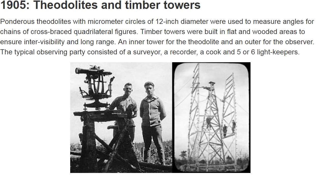
Modern theodolites are now often digital and expensive, but the classic theodolite still works quite well for this purpose. A classic theodolite, like the Würdemann model seen above, consists of an adjustable base that you set to level with adjustment screws and spirit levels. You then use a telescope with a crosshair to sight the distant object (the horizon in our case) and then read off the angle of the telescope for the circular scale.

You can then measure the dip of the ocean horizon from various altitudes. While there's issues of visibility from waves (at very low altitudes) and haze (at higher altitudes), you should be able to get a good range of readings.

It struck me that while this is a great practical experiment to measure the curvature of the Earth (or simply to demonstrate that there is a curvature, for the Flat Earth folk) not many people have a theodolite.

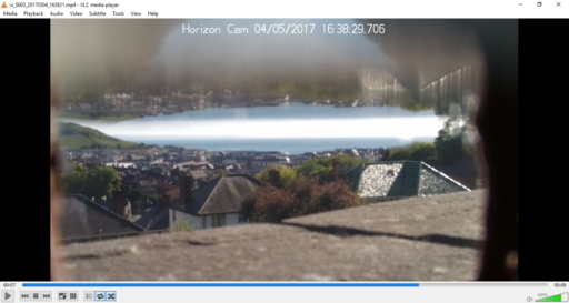
Many people have a smart phone, and you can actually use a "theodolite" app to do simple measurements. Here's one I took from 36,000 feet showing the horizon dipping several degrees below level.


But the app is a little confusing to use for many people, and is not really that easy or accurate for measuring angles when you are below 1000 feet.

So I decided to try making a very simple "theodolite", which is basically a cheap 48 inch spirit level with a bit of cardboard stuck on the end. You rest this on something and adjust it so it is level. You then look along the top edge and see where the ocean horizon is relative to that. If the earth were flat then the ocean horizon would be in line with the top edge. Since it's not, we see the horizon dip below the top edge, and dip more as we get higher - indicating the ocean surface is curved.

For the very simplest experiment - demonstrating that there's a curve - we don't even need to use the bit of cardboard (although it's still helpful). All you have to do is set the level so it's level, and then look along it. If the horizon is below level then you have demonstrated the curvature of the ocean.
20170420-115219-xu99z.jpg
(I'm using a tripod here, but that's just for convenience, you can just put it on a wall or some other object, and adjust it to level by putting things underneath it.)

How do you "look along" the level? It works best if you are some distance behind it, so you can keep both ends (and the horizon) in sufficient focus to see where they all are. What you need is to get the top of the level so it's flat - which you can do by looking slightly to one side and seeing that the top side edge is in line with the top back edge.
20170420-115614-0ng6m.jpg

Unfortunately I'm in a valley, so the surrounding ridges are above level for me, but we can still do measurements. I've marked the cardboard in 1/4" increments, and you can see that the "horizon" here is 3/4" above level.

What's that in degrees? It's relatively simple trigonometry since the eye, the end of the level, and the mark matching the horizon all form a nice triangle.
20170420-121350-bpjcp.jpg
All you need to know is the distance from the eye (or preferably camera) position to the far end of the level. For simplicity I recommend making the distance to the near end the same same as the length of the level. Here I've got a 48" level, so I put my camera 48" behind it, giving a total distance of 96"

So, simply trig, the angle is arctan(height/distance) or arctan(0.75/96) in degrees = 0.45 degrees. I generally use Google as a calculator for things like this:
20170420-125458-3j3rd.jpg


How accurate is this? Generally with a spirit level if you've got the bubble between the lines then that's level to better than 0.1°. Looking at the cardboard scale, if you've got a sharp horizon you can easily get better than 0.1" resolution, which is better than 0.05°. So with a little care you should be able to at least get accuracy of 0.1°, and probably several times that.

The expected values of the horizon dip are:
20170420-124346-3qpvl.jpg

So with an accuracy better than 0.1° we should easily be able to roughly measure the dip of the ocean horizon even if we only have 400 feet (or less) to play with. Notice the change in the dip angle is most rapid when you are low down, the change from 100 to 1000 feet is about the same as from 30,000 to 40,000 feet.

While this is all mostly a fun science experiment. It's also an attempt by me to create a series of simple tests that anyone can do to detect the curvature of the earth - specifically aimed at people who believe the Earth is flat. That belief is only sustainable by rejecting all evidence from conventional authority (photos from space are generally dismissed as fake), and so the only evidence a hard-core flat earth believer will accept is the evidence of their own eyes.

Here I hope I have provided a means of simply getting that evidence. I'd encourage any flat earth believer who lives near the ocean to give it a go, and report back their results. If you find that the horizon does not always rise to eye level then perhaps that might lead to you doing some other experiments, and eventually figuring out the true shape of the Earth for yourself.


See also:
 
Last edited:
Looks good. You can even do that where you have stationary ship, lighthouse, or similar offshore structure, part of whose image lies below the horizon, and which hidden part is revealed as the altitude of the observer increases. That gives you a horizon visual yarstick, all of which, of course, would be visible on a flat earth, but which clearly is not.
 
It's not common place any more, but for centuries in navigation and early land navigation and surveying, solar and astral observations would be used with this equipment. All state boundaries in the US were layed out with a theodolite, and if observations were made to follow the earths curvature, state boundaries would be wildly different. These methods can be fairly easily grasped with some study and practice. 2nd year Land Surveying undergraduates complete labs on such topics.
 
All state boundaries in the US were layed out with a theodolite, and if observations were made to follow the earths curvature, state boundaries would be wildly different.

Surely though if they were using solar and astral observation they were automatically factoring in the earth's curvature. State boundaries that did not follow natural features (like rivers) were defined using latitude and longitude, which are spherical coordinates.

Errors might come later at a more local level. Plane surveying is used in some locales, but you can't extend it indefinitely. Factoring in the earths curvature when surveying has been done since the 1600s when Snell invented modern triangulation.
https://en.wikipedia.org/wiki/Surveying#Modern_surveying
Dutch mathematician Willebrord Snellius (a.k.a. Snel van Royen) introduced the modern systematic use of triangulation. In 1615 he surveyed the distance from Alkmaar to Breda, approximately 72 miles (116,1 kilometres). He underestimated this distance by 3.5%. The survey was a chain of quadrangles containing 33 triangles in all. Snell showed how planar formulae could be corrected to allow for the curvature of the earth. He also showed how to resection, or calculate, the position of a point inside a triangle using the angles cast between the vertices at the unknown point. These could be measured more accurately than bearings of the vertices, which depended on a compass. His work established the idea of surveying a primary network of control points, and locating subsidiary points inside the primary network later. Between 1733 and 1740, Jacques Cassini and his son César undertook the first triangulation of France. They included a re-surveying of the meridian arc, leading to the publication in 1745 of the first map of France constructed on rigorous principles. By this time, triangulation methods were by then well established for local map-making.
Content from External Source
 
While looking at the history of surveying I wondered if there were other ways of making a DIY line-of-sight theodolite like mine. After all a 4' level is a bit large to tote around.

One alternative to a spirit level is a water level, basically a tube filled with water, with a container at each end allowing you to see the water height (although at the simplest you could just use a section of clear plastic tubing.
640px-Schlauchwaage_Schematik.svg.png

The line between the two is then essentially level (technically it's level at the midpoint, but for practical purposes it's level at either end.)

So you might be able to make a more compact sighting level using a water level. The visual evidence of "level" might be more compelling than using the spirit/bubble level, as you would be able to see the water level and the horizon in the same image. You might even be able to use a relatively short section of pipe with some vertical transparent bits that you could hold in front of an iPhone to, at the least, demonstrate the ocean horizon falls below level.

Perhaps a trip to Home Depot is in order.....
http://www.homedepot.com/p/Sioux-Ch...-D-x-2-ft-Clear-Vinyl-Tubing-HSVUR2/204407882
20170426-095230-qxrac.jpg
 
Surely though if they were using solar and astral observation they were automatically factoring in the earth's curvature. State boundaries that did not follow natural features (like rivers) were defined using latitude and longitude, which are spherical coordinates.

Errors might come later at a more local level. Plane surveying is used in some locales, but you can't extend it indefinitely. Factoring in the earths curvature when surveying has been done since the 1600s when Snell invented modern triangulation.
https://en.wikipedia.org/wiki/Surveying#Modern_surveying
Dutch mathematician Willebrord Snellius (a.k.a. Snel van Royen) introduced the modern systematic use of triangulation. In 1615 he surveyed the distance from Alkmaar to Breda, approximately 72 miles (116,1 kilometres). He underestimated this distance by 3.5%. The survey was a chain of quadrangles containing 33 triangles in all. Snell showed how planar formulae could be corrected to allow for the curvature of the earth. He also showed how to resection, or calculate, the position of a point inside a triangle using the angles cast between the vertices at the unknown point. These could be measured more accurately than bearings of the vertices, which depended on a compass. His work established the idea of surveying a primary network of control points, and locating subsidiary points inside the primary network later. Between 1733 and 1740, Jacques Cassini and his son César undertook the first triangulation of France. They included a re-surveying of the meridian arc, leading to the publication in 1745 of the first map of France constructed on rigorous principles. By this time, triangulation methods were by then well established for local map-making.
Content from External Source


You would be correct in saying that they automatically would then factor in these observations. Problems in surveys would arise when not making these observations and just using magnetic north to create boundary lines. These issues were all worked out in Ohio before the Public Land Survey System would be later used to divide the country in what we now have as our 48 contiguous states.

As to your post about using a system of tubes and water to create a level plane, I have a historical example of this. Roman engineers (which there were multiple types based off of there specific tasks, but in this case military engineers) would use a CHOROBATES. The link below briefly describes the use of this instrument.

http://www.surveyhistory.org/roman_surveying1.htm
 
It's important for everyone here to have a clear notion of the difference between plane surveying and geodetic surveying. Plane surveyors and geodetic surveyors have completely different education tracks and professions. The split between the two can be illustrated by this article from 2,000.

https://web.archive.org/web/2017042.../articles/86585-geodetic-surveying-made-plain

A decade or two ago, I was the instructor for some introductory surveying courses at a community college. In the first class we would define “plane surveying” as surveying that did not take into consideration the curvature of earth, and “geodetic surveying” as that which did. That was about the only time the two categories received anywhere near equal attention. Oh, we would point out (still in that first lecture) some of the real-world evidence of a non-flat earth, such as the fact that the length of an 11.5-mile arc on the earth's surface is only five hundredths of a foot longer than its subtended chord, or that the sum of the angles in a spherical triangle on the earth’s surface having an area of 75 square miles is only one second greater than the angle sum of the same size plane triangle. (Even today I get a kick out of those dramatic tidbits. I’m sure a real geodesist would roll his or her eyes at such trivia!) But those examples were used as reasons for not focusing—no, for not mentioning—geodetic concepts for the rest of the semester. We would end the ten-minute token nod to geodetic surveying with the tongue-in-cheek remark, “Therefore, for this class, we will respect the time-honored principle handed down through the ages—that the earth is flat.” And, truth be known, that’s probably not a bad narrowing of a dauntingly broad subject.

But more than narrowing, it was simply that few rank-and-file surveyors in private practice ever had occasion to use geodetic concepts in their daily work. Even when we dutifully enrolled in the occasional State Plane Coordinate seminar, the principles quickly faded from memory from lack of use. If a surveyor from the general population had ever even heard of the geoid and its relationship to the ellipsoid, and where mean sea level fit into the picture, hearing about it was as far it went. We stayed proficient in the subjects we used everyday. But that … was then.

And this is now … boy, is it ever! That picture has changed and continues to change even as we discuss it. A trio of factors has pushed learning about geodetic surveying and its principles right up to the top of Mr. Everyday Surveyor’s to-do list. Perhaps the earliest of these three factors to emerge was the increasing requirement imposed at various jurisdictional levels that subdivisions, or in some cases all surveys of record, be tied to a master coordinate system. That system is generally State Plane or some other large, comprehensive coordinate system. Whatever the format, some knowledge of grid coordinates vs. surface coordinates, geodetic north vs. grid north, and the like, is essential for the surveyor to operate successfully in that sphere (no pun intended). Incidentally, I saw a question on rpls.com recently about this topic. The consensus of the dialog agreed that all surveys going onto a uniform system is coming in the not too distant future.

The primary reason for this uniform coordinate system requirement brings us to the second factor spotlighting geodetic surveying: the proliferation of Geographic Information Systems across the country. Some of us have seen first-hand how chaotic a GIS can be when the coordinate system is not fully understood. Or, if not chaotic, at least falling short of its intended use due to unreliable accuracies. Those problems are easily fixed with a stiff dose of geodetic surveying expertise.
Content from External Source
 
Last edited by a moderator:
Further into that article:


Earlier I mentioned my fascination with round-earth trivia. Equally high on the fascination index is the wealth of lore and legend surrounding the old USC&GS (now NGS) and its efforts to establish reliable geodetic control nationwide. Most, if not all, geodetic surveyors agree that NAD83 and its upgrade, High Accuracy Reference Network are superior to (and should be used instead of) NAD27. But agreement is also widespread that the establishment of NAD27 was a remarkable achievement for its time. Imagine establishing first-order control almost exclusively with triangulation! How accurate must those angles have been turned! Listening to an account of mere routine field procedures can generate an out and out … well, thrill in the bones of almost any surveyor. Picture it: nighttime atop a Bilby tower or a mountain, occupying a point with a 40-pound Wild T3, huge by our standards but considered small when introduced, turning to as many as dozens of lights measuring angles read to a decimal part of a second on an optical micrometer, taking readings on each point with 16 different plate orientations … to us it’s the stuff of legends, but to those guys just another day’s—I mean night’s—work.

NGS’s parent agency, the National Oceanic and Atmospheric Administration maintains a fine historical website, with a large segment dedicated to USC&GS. It’s at www.history.noaa.gov and it’s highly recommended reading for anyone interested in such accounts.
Content from External Source
These are some photos from this site: https://web.archive.org/web/2017042...ystems/canadian-spatial-reference-system/9110


Content from External Source
This time stamped video shows some examples of historical methods and equipment of geodetic surveying including electronic methods:

 
Last edited by a moderator:
So I got some of this, like $4.50:
20170426-182940-3lxvn.jpg

Cut a bit and propped it up, added some cranberry juice.
20170426-183024-upuxd.jpg
This is from an iPhone about two feet away:
20170426-183132-c4plp.jpg

The idea here is simply demonstrate that the ocean horizon is below level in a visually convincing way. It should be inarguable that the two ends of the juice are level, and hence if the ocean horizon is a bit below them then it's not "rising to meet the eye".

To get the levels exact I took a movie, moving very slowly above and below the level point, then picked the best frame.
 
This is using a better camera, but I'm hampered by the light. I'll see what it looks like in the sun tomorrow.

20170426-184510-no4sx.jpg
 
This is using a better camera, but I'm hampered by the light. I'll see what it looks like in the sun tomorrow.
What if you floated a black object on both ends inside the tube, would that make the line more clear/obvious?

Edit: ..then connecting the 2 black floating objects with something straight? Then you could scale this wider?
 
What if you floated a black object on both ends inside the tube, would that make the line more clear/obvious?

Edit: ..then connecting the 2 black floating objects with something straight? Then you could scale this wider?
Adding floats that protrude from the tubes would increase accuracy. However you lose the symmetry of a simple tube and liquid. I like the very obvious visual of two unquestionable levels.
 
Wouldn't something like a clear glass of water be enough? just put it on a table and wait for the water to be still and use the surface.

If you use some kind of measuring cup, with a scale down the side, you might be able to translate it into degrees
 
Wouldn't something like a clear glass of water be enough? just put it on a table and wait for the water to be still and use the surface.

If you use some kind of measuring cup, with a scale down the side, you might be able to translate it into degrees
A single small flat surface would be far more difficult to align the camera with. The idea of having two containers connected by a tube (or a single long level) is that it gives you a nice long baseline to line your camera up with, giving more accuracy.


For example say you are able to align the front and back of the level surface with an error of 0.1mm (0.01cm). If you use a single glass 10cm wide, then this equates to an angle off horizontal of arctan (0.01/10) = 0.057°.

Now you use two containers connected by a tube, so that the distance from front to back is 100cm (1 metre). Again you align the front and the back with an error of 0.01cm. Now the angle off horizontal is arctan (0.01/100) = 0.0057°, 10 times more accurate for the same vertical accuracy.


Also I think in a single small glass the effect of the meniscus would make it hard to find the level.
 
I think part of the point of the tutorial is so that other people will/can take photos.

Exactly. Flat Earth thinking is based on "Zetetic" philosophy, where you don't trust authorities, but instead check things for yourself. Here I'm trying to provide simple methods where they can investigate if the horizon actually dips below eye level.
 
20170427-132640-gbv51.jpg
20170427-132857-0gv9x.jpg

Two plastic containers with about five feet of tube between them. Cranberry juice. You do need to let the levels settle, as with this tube it takes a few seconds, so it needs to be on a surface (or two supports).

Here it is lined up ready to measure my sadly absent horizon.
20170427-134849-j8dlo.jpg

After making it, it's obviously going to work. However I'd recommend the individual just uses the regular level method I described in the first post. This was just too much work.

However I do think this level would be good for a video demonstration, where you could put them on a wall, and walk around with the camera all in one shot for the demonstration.
 
if you made the tube into a hoola hoop (connectors are like 75 cents), the lines would be smaller of course but it would be pretty easy to travel with and fun for the whole family :)

Hmm, I could make a mini one with some hot glue and gorilla tape. Hold on.....
 
I think that's even better than the [spirit] level for the layman as it's easier to hold up to eye level (and see the lines) and check stuff out. neat.

Unfortunately it's bit tricky to hold by hand without the water levels wobbling. However that' easily solved by just propping it up on something.
 
Last edited:
Unfortunately it's bit tricky to told by hand without the water levels wobbling. However that' easily solved by just propping it up on something.
and it doesn't really have to be straight vertically right? like if you lean it against a rock.. because the water will level off regardless.
 
The flat earthers have already been using the water level apparatus to try and prove their point. In my opinion this video actually reveals a drop.

Not really, as it's only from eight feet up. He does it at 196 feet here:
[Deleted video]
Source: https://www.youtube.com/watch?v=WpRRQcFsRUk&t=0s


This actually does seem to show a drop. Note at around 200 feet the drop would only be a quarter of a degree.
20170427-163427-sptco.jpg

[Edit] On closer inspection it's impossible to tell. The level is moving around so much, as I mentioned as a problem earlier. He needs to fix the tube and move the camera
Flat-water-flat-earth-Hand-held-horizon-eye-level-test--experiment-1.gif
 
Last edited:
Maybe the water level needs to be anchored on two stakes. A string could then be stretched between the two water level points to serve as a sight line. Maybe even better, to remove some bias, the string could first be aligned with the horizon and then water added till it rises to the closest string height. The distance between the string and the water level at the furthest point could be used to calculate the drop. If the stakes were 10' apart that .25° would be 0.5".

Still a bit of work.:)
 
Inspired by Mick's efforts, I have created the almost foolproof Horizon Cam(tm). It seems that today the Earth is almost flat..View attachment 26614 Details later when my camera is charged. Later video is slightly more convincing of roundness.

DSCF4503.jpg

20170504-080514-1c76i.jpg
 

Attachments

  • vi_0000_20170504_133327.mp4
    16.4 MB · Views: 1,258
Last edited by a moderator:
Hmm, now I have the urge to go the thrift store and buy an old fish tank.

Also move back to the coast :(
 
Oh wait, the lens is underwater, and you are using the internal reflection of the underneath of the water surface?
 
Fascinating. Looks like you are videoing the reflection off a water surface aligned half way over the lens?
The lense is looking through the water just below the surface. (I think).You need a very small lense or a big tank. I was using the Raspberry Pi camera which seems to be about 1mm. dia. I think the image fades towards the top as you are not then getting total internal reflection or it might be seeing the near meniscus. Towards the horizon it fades because the path from the lense is missing the water surface. I need a bigger fish tank really, but I wanted something portable. A mobile phone cam would probably work ok with a longer tank.
 

Attachments

  • Horizon Capture.PNG
    Horizon Capture.PNG
    1.2 MB · Views: 632
Last edited:
So, if there's a gap between the normal and inverted horizon lines, that equals the dip of the horizon? I'm trying to visualize why that would be so.

The inverted image has reduced brightness, contrast and resolution. My first thought was that:

-The inverted image is being produced by a surface which is at an angle to the source of reflected light; so the total amount of light producing the inverted image is lower than that of the normal image.

But my second thought is more significant I think:

-The inverted image is being produced by a partial specular reflection from the water surface. Only some of the light is specularly reflected, while most(?) of it is passing through. A one-way mirror. I'm not sure how (or even if) the angle affects the amount of light that's reflected.

Then the problem is made worse (for both images) by the light that passed through the water surface reflecting off the surface of the cylinder and back to the lens. I think painting that surface matte black would help improve overall brightness and contrast.

Plugging that fill hole in the cylinder would help too.

And black out the acrylic window just above the water surface with tape. From life experience a one-way mirror works best when there's a dark room behind it. Make the area in the cylinder above the water surface as dark as possible.

Edit: Looking at the photo again, it looks as if you put a baffle in the upper part of the cylinder. I can't quite make it out.
 
Last edited:
So, if there's a gap between the normal and inverted horizon lines, that equals the dip of the horizon?

If you are above the horizon, then you have to look down to see it. Looking up at a level mirror (the water surface) will let you see it, providing it is below level.

So if the horizon is visible at all then that proves it's lower than level (assuming the water surface is level, and assuming no other confounding factors, like refraction in the air/perspex/water transitions.)

The higher you are the more you'd have to look down, so the more visible the horizon will be.

In the above, the horizon is not visible, because the mirror (water surface) is too short.
 
Hmmmm. And the mirror needs to be absolutely level, thus the water surface.

Using a longer tube would help 3 problems: The partial image, internal reflections, and you'd be able to use a (physically) larger lens because you'd be able to focus on a more distant part of the water surface (I think. I'm still working that last one out).
 
Last edited:
So, if there's a gap between the normal and inverted horizon lines, that equals the dip of the horizon? I'm trying to visualize why that would be so.

The inverted image has reduced brightness, contrast and resolution. My first thought was that:

-The inverted image is being produced by a surface which is at an angle to the source of reflected light; so the total amount of light producing the inverted image is lower than that of the normal image.

But my second thought is more significant I think:

-The inverted image is being produce by a partial specular reflection from the water surface. Only some of the light is specularly reflected, while most(?) of it is passing through. A one-way mirror. I'm not sure how (or even if) the angle affects the amount of light that's reflected.

Then the problem is made worse (for both images) by the light that passed through the water surface reflecting off the surface of the cylinder and back to the lens. I think painting that surface matte black would help improve overall brightness and contrast.

Plugging that fill hole in the cylinder would help too.

And black out the acrylic window just above the water surface with tape. From life experience a one-way mirror works best when there's a dark room behind it. Make the area in the cylinder above the water surface as dark as possible.

Edit: Looking at the photo again, it looks as if you put a baffle in the upper part of the cylinder. I can't quite make it out.

I need to think about this some more. I only got the camera yesterday. BTW My elevation is 50 metres. The webserver for the cam was this: http://elinux.org/RPi-Cam-Web-Interface
 
Back
Top