MortarBoarder
Member
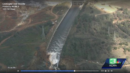
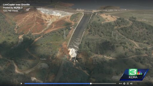
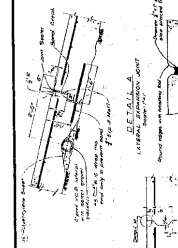
In the main thread, the joints were described as step joints. Perhaps the leakage through those joints are expected source of the water. 100,000 cfs is a lot of water.
It looks like the bottom slabs used step joints where one slab overlapped the other. The depth of the step was only about six inches.
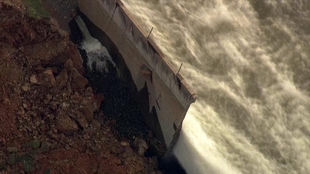
More worrisome -- where the slabs are broken, the rebar appears pristine and there is much damage to the concrete -- the rebar did its job. But at the joints there is virtually no sign of any reinforcing spanning the joints.
Joint -- no rebar
View attachment 24887
Joint -- no rebar (but lots of apparently empty dowel holes)
View attachment 24888
Joint -- no rebar
View attachment 24890
Joint -- no rebar
View attachment 24891
Broken slab -- lots of like-new rebar.
View attachment 24889
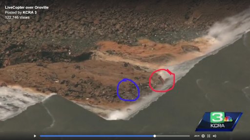
In some places there appears to be rebar ties into the ground
View attachment 24892
Other than these widely spaced anchors, it appears the slabs were poured on fill. There is no evidence of concrete adhered to the rock.
No evidence of sealing, although the 100k cfs rinse cycle might have cleared any evidence of that.
I do not understand the lack of ties between the slabs. And so few anchors on a slope.
")