
sweepleader
Member
Particularly for appurtenant structures (such as spillways and outlet works) associated with high velocity, high volume releases, care must be taken so that the drainage system is not subjected to adverse hydraulics, which can damage or fail the appurtenant structure. Two conditions that should be evaluated include: (1) excessive back pressure, which could introduce hydrostatic (uplift) pressure beneath a spillway conveyance feature and/or terminal structure; and (2) stagnation pressure that could be introduced through cracks and/or open joints along a conveyance feature and/or terminal structure, leading to pressurizing the drainage system [42]. In other words, there should generally be no direct path (such as drains, open joints or cracks) through the floor slabs and walls that are subject to high velocity, high volume flow conditions.
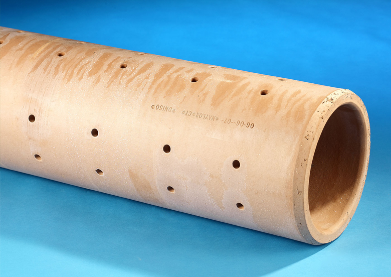
Air demand must be considered, which could be associated with providing a "vacuum break" to allow air to eliminate lowered pressures induced by high velocity flow across drain outlets (see figure 3.7.3.1-4). Inlets or intakes which provide the air should be located above the maximum tailwater level.
New member, lurking for a week. Great site.
The quoted test text is from post #21 above, the referenced "techreferences" document, page 3-125. There is another similar reference somewhere above or in the original thread that I have not been able to find that shows clear plan views of vented drains.
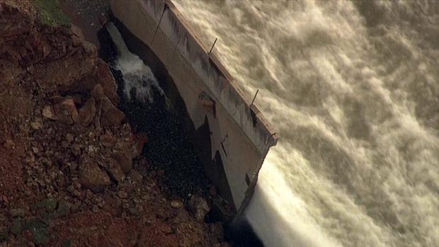
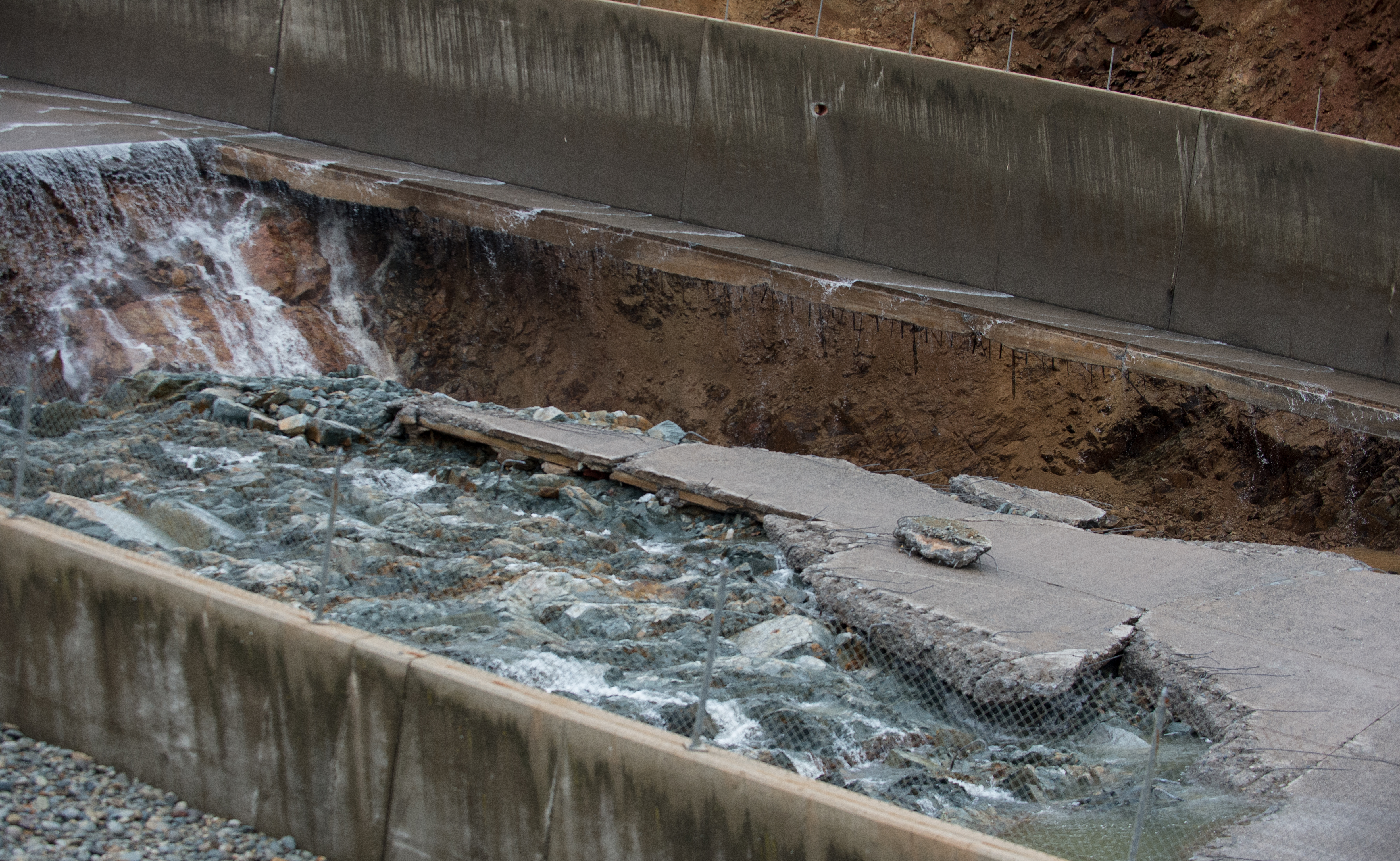
The first paragraph suggests that the flow of water out of the wall ports might indicate that the flow of water through the slabs to the drains system is excessive which to me suggests that the folks running the dam should have thought about that years ago since even much older photos show large drain flows.
The second paragraph references the need to allow air to bleed into the drains to allow proper water flow.
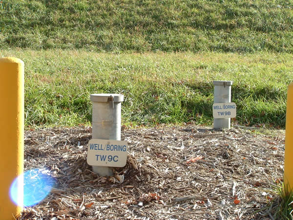
I believe the yellow arrows point to air vents.
