In post #43, samfriday asks
External Quote:
Any other comments on the footage?
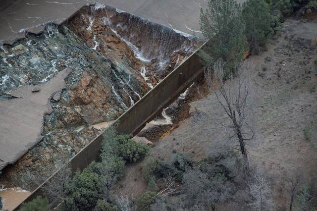
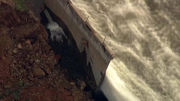
. I do have one, more of a question for someone who is knowledgeable about engineering and/or the construction plans. I notice in Alan Kuentz's video, when he zooms out a bit, the spillway is visible in the right foreground, and you can see flow pouring in through drain holes in the side wall. That flow has to be coming from some form of drain system, which is fully charged with water: either perforated pipes in saturated soil some distance to the sides in the hillside, or just local drains, in drain rock just outside the spillway sidewall. Maybe no pipes at all, just the drain rock and something to keep it from coming right through the drain holes. The latter seems implausible to me, if there's drain rock all the way down the very steep hillside, well, that's a really steep gradient, and drain rock percolates very quickly. It would take a LOT of water continually entering that side drain to back up so that every one of those drain holes is flowing. There would be surface flow outside the spillway, up at that level, not just below the breach. On the other hand, if those drain holes are the outfalls for a hillside drain system, it would mean there's a whole lot of water saturating however much of the hillside the drains are in. And continually flowing in. One wonders, is it really raining that hard already there? Whether it is or not, where's the water coming from that's pouring through those drain holes into the spillway?