The predicted response of the system is summarized in Table 8–2. The first failures observed were of the
shear studs, which were produced by axial expansion of the floor beams, and which began to occur at
fairly low beam temperature of 103 °C. Axial expansion of the girder then led to shear failure of the bolts
at the connection to Column 79; and, at a girder temperature of 164 °C, all four erection bolts had failed,
leaving that end of the girder essentially unrestrained against rotation. Continued axial expansion of the
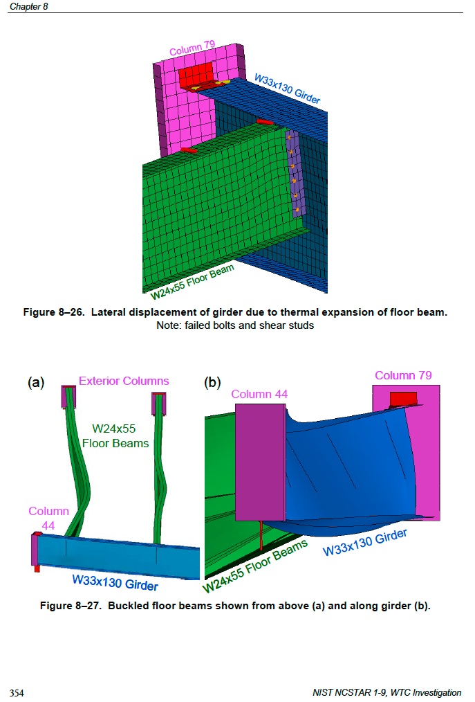
floor beams pushed the girder laterally at Column 79, as shown in Figure 8–26, in which failed shear
studs and bolts were evident. When the beam temperatures had reached 300 °C, all but three shear studs
in the model had failed due to axial expansion of the beams, leaving the top flanges of the beams
essentially unrestrained laterally. Continued axial expansion of the girder caused it to bear against the face
of Column 79, generating large axial forces that led to failure of the bolts connecting the girder to Column
44. When the girder temperature had reached 398 °C, all four erection bolts at Column 44 had
failed, leaving the girder essentially unrestrained against rotation at both ends. After failure of the erection
bolts in the seat at Column 44, continued axial expansion of the floor beams pushed the girder laterally,
where it came to bear against the inside of the column flange. Axial compression then increased in the
floor beams, and at a beam temperature of 436 °C, the northmost beam began to buckle laterally.
Buckling of other floor beams followed as shown in Figure 8–27 (a), leading to collapse of the floor
system, and rocking of the girder off its seat at Column 79 as shown in Figure 8–27 (b). The collapse
process took time to occur in the LS-DYNA analysis, during which the temperatures had ramped up to
their maximum values in the simulation.

 ], is this satisfactory? For a moment there I wasn't sure what the response would be.