I prefer the forum format but thanks for the interest. I don't have experience in structural forensics or fire engineering, but I do have a structural background and deal with steel structures at high temperatures so I may be of some limited usefulness. I'm inclined towards skepticism, but most of the 9/11 skeptics I have come across on the internet just don't have the technical background to make their case persuasively and they do more harm to their cause in the eyes of those with relevant expertise. I came across your concerns after seeing that Ben Swann video and was impressed with the quality and research that went into the questions raised ... not to mention and open dialog and mind.
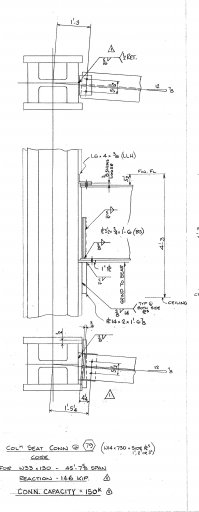
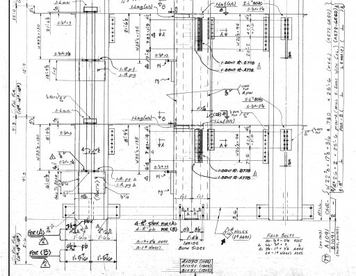
That said, I'll look at detail 79. First, may I ask, what is the importance of the classification of this detail as moment resisting? I have read this thread, but may have skimmed past the discussion.
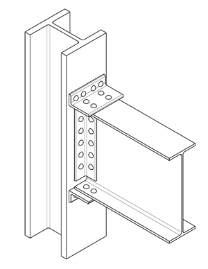
If you ask a structural engineer to classify the connection as either a shear or moment connection, they will say shear. If you get access to the AISC steel construction manual, there's a tab for shear connections and there's a section for unstiffened seated shear connections that looks very similar (standards may have changed since the mid-80's.) Another hint that the connection was designed and analyzed only for shear is that the detail gives only the reaction and capacity in kips and no moments are given. If inclined, I found a design example
here - Example II.A-13.
That said, even shear connections resist some moment. You see that angle bolted to the top and say, yeah, if they cantilever that beam off a column, and you walked to the end, it'd hold your weight. That may be true, but connections classified as shear connections are detailed in a way to allow rotation and the moment capacity is so small as to be taken as zero in analysis. A true moment connection can be partially or fully restrained and frequently have the flanges of the beam complete joint penetration welded to the column. The top angle is for stability only and is not designed for any load. It is simply to keep the beam from having its top flange want to topple to the side in a behavior known as lateral torsional buckling. when a gravity load is loaded on the span
The 5 1/2" x 3/4" stiffener welded to the beam web is either there to prevent local failures in the web or bottom flange due to the high concentrated reaction load or again for rotational stability at the beam end. In summary, when the original engineer was designing this, he was not thinking about fires whatsoever and was just thinking about a beam sitting on a seat. All the other things going on here are standard practice for stability under normal gravity loading.
I agree with some of what you have said here re people doing more harm than good. I thought that the Ben Swan thing did a fair job generally for the time that he had, but didn't quite get the points across in the way I would have. That said, I would have probably still been there now prattling on about stiffeners and plates if it had been me, so given the time, and the average technical awareness of his target audience, I love what he did, and salute Tony for getting this info out there.
I am sure that given the chance Tony would have blown NIST even further out of the water, and i am sure he did off camera. I am well aware of what connection is what and do have access to the info that you cite above. And yes, things have changed a lot since the 80s.
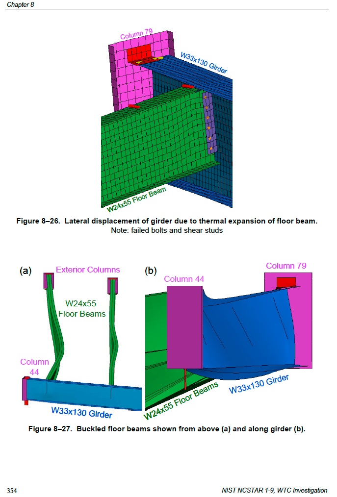
As to the relevance of whether this is moment or not, it is going to resist anything that is getting thrown at it from expansion of beams to the east, and in that sense it is. I think to labour this point is not required for the purposes of this thread, or NISTs analysis, or indeed ours.
As far as the stiffeners are concerned, I have no interest as to intent on the original designers part, what matters here is the function that they would have served within NISTs sequence of events, and that function, hypothetical as it is, is as follows. As the girder is pushed just over 6" to the west the gravity load is no longer over the web and the full load then exerts onto the flange of the girder. This potential overstress is then redistributed from the flange, through the stiffener, back to the web, and in this way the 'walk off' distance is extended and the beam would not fail at 6.25" movement to the west, this figure originally being 5.5", and both being impossible from the thermal expansion of the floor system to the east. NIST could not have got this analysis from an FEA model as it just wouldn't happen in ANSYS or elsewhere. They deemed the element to have failed once it had moved to the halfway point, which is a howler of an error.
In our own analysis we estimated the walk off distance required for failure to be in excess of 9" which is about double that which would be possible. Also we allowed it to expand unrestrained. As for NIST seeing stud failure at 103C in the beam as per table 8-2 at 1.44s (Micks post#354), clarification of this will have to be sought from NIST, and i suspect another erratum and 'typo' confession will result from that, if there indeed is any reply, as such an occurrence is beyond the realms of reality, even for Mr Sunder. If this were possible, I would advise wearing a hard hat next time you boil a kettle inside a steel framed high rise, in case studs start to fall from above.

Also, the stiffener plate is not just welded to the web, it is welded to the flange at 3/8", that flange also being clipped to the lower plate (pf).
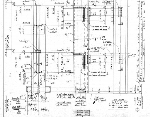
It is great that you are looking at this also, and given that the info is somewhat new to you, if I can help at all in saving you the legwork of trawling through the drawings to find those relevant to the particulars of your research, please just ask, and I will do my best to help.

