Critical Errors and Omissions in WTC7 Report Uncovered

Status
Not open for further replies.
Ok, I think that can be cleared up fairly easily. It is misleading as different frawings show different detail.....
Shear studs are shown in <> brackets as seen on this note from E12/13 (floor framing plan for 12/13)
Revision_I_B.jpg

Revision_I_B.jpg
Here they are shown on the beams in question <24> / <28>
1213Expansion_all columns_beam.jpg

Don't be confused by the () numbers, which are camber indications

I see. I was looking at S-8-19, which was the closest that I found.
Why do you think the studs are omitted here?
 
Last edited:
Because your case seems very weak so far. You've claimed there must be shear studs even though they don't appear on the sheets for that floor, then even if they are there you don't seem very clear on what effect they would have on the expansion (and radiating heat I assume is not something you think is particularly significant). Then you complain about a plate size that NIST corrected a year ago.

And I've not even looked at your "impossible push" math yet. Sorry, but I find video evidence very hard to work with.

Weak ?

that last drawing showed an awful lot of shear studs, represented by all those numbers between the <> brackets. The effect of these studs is to create a monolithic structure between the slab and the supporting structure, it also serves to radiate heat between the two evening out the thermal expansion should there be any. NIST corrected that plate size yet didn't modify its hypothesis to account for it. I'm going to suggest because the hypothesis simply doesn't work once this correction is made. They would need more heat to expand the steel further to knock it off this larger seat. They formerly argued that any additional heat than what they originally predicted would result in sagging rather than pushing. So how is it you can call this line of reasoning weak ?
 
I see. I was looking at S-8-19, which was the closest that I found.
Why do you think the studs are omitted here?
Very fair question. Why would shear studs be shown on all these wind girders off to the edges, and the W24x55 beam below and yet be omitted from the beams that NIST focused in on. Anyway the E12/13 drawing is detail for floor framing at the floor in question, and as I said before, nobody would reasonably disagree that these beams would have studs on them. Hope that cleared that issue up.
 
Last edited by a moderator:
If you look in the construction notes under steel frame you'll most likely see something that says "sheer studs", gives a layout and noted typical as per quantity <> then there will be another note about spacing and where not indicated. I'm guessing you don't have these notes. But there's a ton of bolts on the beams in question all clearly noted, <> from what I could see.

It would be interesting to make a detail drawing to scale of this connection and see if the girder even has room to walk off the seat given that there's a 21-44 set just under 6" away from center line of the column on the back side of the girder in question . Unless I'm reading it wrong, which I might be, looks like it scales to about three feet. I'd have to see some more details.
 
Last edited:
If you look in the construction notes under steel frame you'll most likely see something that says stud, gives a layout and noted typical as per quantity <> then there will be another note about spacing and where not indicated. I'm guessing you don't have these notes. But there's a ton of bolts on the beams in question all clearly noted, <> from what I could see.

It would be interesting to make a detail drawing to scale of this connection and see if the girder even has room to walk off the seat given that there's a 21-44 set just under 6" away from center line of the column on the back side of the girder in question . Unless I'm reading it wrong, which I might be, looks like it scales to about three feet. I'd have to see some more details.
Yeah, we did that, we also did some animations. What I personally think would happen is that the girder would probably go into compression, expand into the column and end up being trapped by the side plates on the side of the column. which overlap the edge. From above it would look something like this

 
Course they also forgot that the surrounding structural members were physically in the path of that failure. But thats a whole other issue I think we should take up separately.
No, here will do. It's the fundamental issue here.

The floor, heated from beneath, would sag initially merely due to the temperature gradient across it. Later on it would tend to straighten, were it not for the fact it was halving its tensile strength, and creeping. When tied together through the columns to all the other floor elements its "center" would move in the direction of any opening in the floor. It would also be trying to squirm (up or down) due to being under compression by the cold, non-expanded exterior periphery.

A hot loaded column, as Column 79 certainly was, would have had plenty of time over seven hours to sag vertically down (allowing everything it supported to do mostly the same) and distort sideways to follow this movement, being at a temperature 125 deg C above its creep transition point.

Being out-of-line in such a manner would have made it extremely prone to buckling collapse: Euler's Law refers to classically vertical/horizontal structures only. Two consecutive collapsed floors would put it past critical even if it were straight.

You have to account for nine or ten inches too much of compressed steel/concrete across the floor plane, with the periphery in tension. I think that if C79's centerline were to be five inches out-of-vertical, then floor collapse and column buckling might well be a simultaneous event.

This could easily happen if the fire moved through the building. Consider one side of the floor already up to temperature, sagging and pulling. Then if the fire crossed to the other side it could heat the floor, causing it to expand before it began to sag. That would create a powerful sideways push on the central columns. This process was observed in the tower fires, where first the floors expanded, pushing the external columns outwards, then they crept and sagged, pulling the same columns inwards.

Uneven heating of the steel causes bending long before it has a chance to expand linearly. One side heats and the other does not, the response of the beam is to bend, without much if any push.
I've already told you that.

It's impossible without the studs, never mind with them. As Boston said, concrete and steel have similar thermal expansion coefficients, the difference is in their ability to conduct heat. I think a good way to think of the function of the studs is to make the floor system act as one element ie composite.
I've already told you that.

NIST supposed that the steel heated up, but the concrete didn't. This sets up a differential thermal expansion between them and would allow them to ignore the composite nature of the floor system.
They didn't at all.

You cannot stop steel expanding and if it is held in place either at the ends or also with studs it would go into compression.
I've already told you that.

The issue here is that NIST played down the studs on the beams. Studs on the girder is a different issue.
Neither issue is important.

Who is to say that there were not studs
The studs aren't an issue.

we allowed for no resistance due to shear studs and the connection still did not fail.
I've already told you that.

That the girder did or didn't have shear studs makes no difference, but I would still reckon it would have them. The floorpan installer would agree with this, as would every other engineer i have ever managed to speak to about this. It is common sense that the floor would be made composite by their use.
I've already told you that.

But just to be clear, before i go further, you now accept that every floor beam to the east of the connection had shear studs on it?
The studs aren't an issue.

They tie the slab system to the support system. Creating a monolithic construct that acts as one unit under load.
I've already told you that.

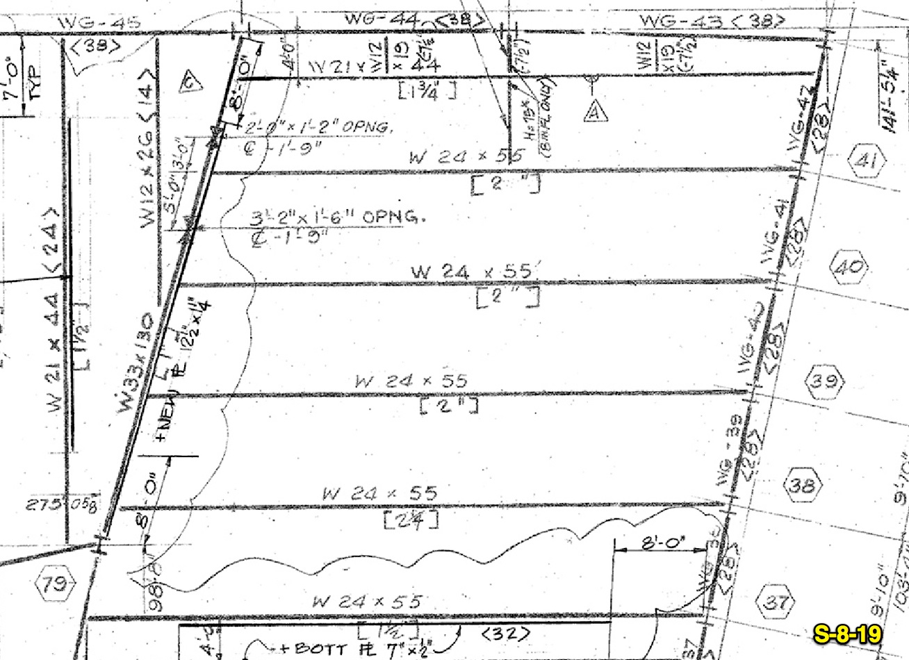
Weak? that last drawing showed an awful lot of shear studs, represented by all those numbers between the <> brackets. The effect of these studs is to create a monolithic structure between the slab and the supporting structure, it also serves to radiate heat between the two evening out the thermal expansion should there be any. NIST corrected that plate size yet didn't modify its hypothesis to account for it.
The monolithic structure is quite probably that which caused column 79 to fail.

I'm going to suggest because the hypothesis simply doesn't work once this correction is made.
I don't believe that that is their hypothesis. If it was, it never worked anyway.

They would need more heat to expand the steel further to knock it off this larger seat. They formerly argued that any additional heat than what they originally predicted would result in sagging rather than pushing. So how is it you can call this line of reasoning weak?
This line of reasoning is totally weak, because it addresses nothing more than ONE SIDE OF THIS COLUMN.

Yeah, we did that, we also did some animations. What I personally think would happen is that the girder would probably go into compression, expand into the column and end up being trapped by the side plates on the side of the column. which overlap the edge. From above it would look something like this.

Except that apparently there's an invisible partition allowing the floor to the right to be heated, and nothing at all happening to the left of column 79.
There proudly stands column 79, perfectly erect and unaffected by seven hours at 600 deg C.
The girders to the right expand without sagging (well, you wouldn't see it from above, eh?) so they never pulled a thing.
The girders to the left never expanded, perhaps at a different time, and never pushed as those on the right pulled.
Is that your idea of a timeline?
Your "animation" is altogether and absolutely irrelevant. Got any more?

If not I have some concrete and a sledgehammer to crush it up with. Go play a cool hand.
 
Last edited:
Why not post a count of the poster that uses the most video evidence? My money's on you being number 1. How many times have we seen Verinage demolitions in VIDEO?

I prefer animated GIFs :)

But that's still just an example of verinage, not some complicated discussion of multiple points with multiple diagrams and multiple numbers and equation. That sort of things needs to be written down, with diagrams.
 
I prefer animated GIFs :)

But that's still just an example of verinage, not some complicated discussion of multiple points with multiple diagrams and multiple numbers and equation. That sort of things needs to be written down, with diagrams.
verinage won't work on a steel frame though. I presume you are talking about the balzak demo?
 
Very fair question. Why would shear studs be shown on all these wind girders off to the edges, and the W24x55 beam below and yet be omitted from the beams that NIST focused in on. Anyway the E12/13 drawing is detail for floor framing at the floor in question, and as I said before, nobody would reasonably disagree that these beams would have studs on them. Hope that cleared that issue up.

Okay, so the beams have shear studs, but the girder does not. I've still not hear how the shear studs would constrain expansion. Gerry, are you going with Boston's "they radiate heat" argument, or would they make a mechanical difference?
 
verinage won't work on a steel frame though. I presume you are talking about the balzak demo?

It would work if you managed to destroy a couple of floors, like in the WTC. I'm not referring to any particular verinage example. There's quite a few.
 
Okay, so the beams have shear studs, but the girder does not. I've still not hear how the shear studs would constrain expansion. Gerry, are you going with Bostons "they radiate heat" argument, or would they make a mechanical difference?
It's not that kind of black and white choice. Of course they would radiate heat, they are steel, steel conducts, and they are attached to a hot bit of steel, therefor they radiate heat. They also serve a mechanical function of making the floor system composite.
 
It would work if you managed to destroy a couple of floors, like in the WTC. I'm not referring to any particular verinage example. There's quite a few.
Show me one on a steel frame, I have studied demolitions extensively, and been in engineering for a long time and i have never heard of this on a steel frame. In verinage you can see the conservation of momentum kick in and the towers in comparison accelerated constantly.
 
........
I've already told you that.


I've already told you that.


They didn't at all.


I've already told you that.


Neither issue is important.


The studs aren't an issue.


I've already told you that.


I've already told you that.


The studs aren't an issue.


I've already told you that.


The monolithic structure is quite probably that which caused column 79 to fail.


I don't believe that that is their hypothesis. If it was, it never worked anyway.


This line of reasoning is totally weak, because it addresses nothing more than ONE SIDE OF THIS COLUMN.


There proudly stands column 79, perfectly erect and unaffected by seven hours at 600 deg C.

If not I have some concrete and a sledgehammer to crush it up with. Go play a cool hand.

seven hours at 600 deg C.

Haven't you been caught making up numbers enough already?

ps and I get a month in the MB Gulag for a slightly sarcastic remark?
 
Show me one on a steel frame, I have studied demolitions extensively, and been in engineering for a long time and i have never heard of this on a steel frame. In verinage you can see the conservation of momentum kick in and the towers in comparison accelerated constantly.

Obviously nobody is going to actually use it. You don't want steel beams flying everywhere, messy and dangerous. Regular bottom up demolition with charges on every floor would be called for. But since you don't think WTC1/2 would have collapsed, then obviously you would not think it would work, as it's the same thing. So maybe that argument could be consolidated.
 
Can you post a copy of the spreadsheet you use in the second video?
I don't have that to hand, it's on disc somewhere. I don't mind going over the method we used, it's pretty straight forward. I do have the specific maths for the expansion somewhere, I will find that and post it. It is way more detailed.
 
Can you post a copy of the spreadsheet you use in the second video?
Re stud calculation:-

CSA of W24 x 55 beam=15.986 sq. inches, the modulus of elasticity of steel is 29 million lbs./sq. inch, length is 52 feet x 12 inches/foot = 624 inches
force generated by beam for a 5 inch expansion is force = [5 inches x 15.986 sq. inches x 29,000,000 lbs./sq. inch] / 624 inches = 3,714,753 lbs, and for five beams would be 18,573,768 lbs buckling force = [Pi^2 x modulus of elasticity of steel x area moment of inertia] / [(effective length factor x unsupported length of beam)^2] = [9.8696 x 29,000,000 lbs/sq. inch x 29.1 in^4]/[(2 x 624 inches)^2] = 5,347 lbs, so the max force of the 5 beams is 26,738 lbs.30 x 3/4" diameter shear studs on the girder, so their total cross sectional area was Pi x R^2 x 30 = 13.25 sq. inches. The shear stress is just force/unit area and is thus 26,738 lbs. / 13.25 sq. inches = 2,018 psi
The shear studs would have had a tensile yield of 36,000 psi and a shear yield of 57.7% of that at 20,772 psi.

So, the shear stress would only be 10% of what the shear studs could take.
 
Haven't you been caught making up numbers enough already?
I'm quite willing to shorten that time to around five hours. Not so keen with the temperatures, though.

He stated - "That report should explain the cause and mechanics of the collapse in great detail."
I agree, it should, however it doesn't.
Even I agree.

They had to, seeing as it collapsed so evenly.
It didn't collapse evenly.

the fires were long since burned out at floor 12 by the time of the collapse.
And then you suppose they cooled down. :)

You then ask "Are you implying that you know more about what happened on 9/11, as well as the logistics surrounding WTC7, than Nigro? I am saying it very overtly and clearly. Yes.
That's not a great claim to fame.

Yes. So it would be totally stupid NOT to heat the concrete that made up the floor wouldn't it?
Of course. As stupid as connecting column 79 to a girder with WTC7 in absentio, so-to-speak.

"Seven hours" - What a load of utter shite.
I'm perfectly agreeable to making it say, five.

The point is that where the fire moved, there was sufficient time for the steel to get up to the room temperature at the ceiling. The insulation would have lost the battle after typically two hours. And once the steel was up to temperature (600 deg C) it remained that way, because it was insulated.

Where fires existed in contiguous floors, and where they were only working on one side or the other of a floor, were occasions where extreme side forces could be exerted on the 47 story-high columns. They, too, were hot near these combinations, and would have distorted sideways and downwards due to being loaded both from above and the side in combination, while being able to creep. The floors in such combinations would be sagging or maybe even bulging, and puckering about their openings.

Then is when those stupid studs might well come into play. If they let go somewhere, just somewhere... it's a sudden sideways force on a heavily-loaded column inches off its axis, and the floor beneath is going to receive a sudden blow from above...
 
Re stud calculation:-

CSA of W24 x 55 beam=15.986 sq. inches, the modulus of elasticity of steel is 29 million lbs./sq. inch, length is 52 feet x 12 inches/foot = 624 inches
force generated by beam for a 5 inch expansion is force = [5 inches x 15.986 sq. inches x 29,000,000 lbs./sq. inch] / 624 inches = 3,714,753 lbs, and for five beams would be 18,573,768 lbs buckling force = [Pi^2 x modulus of elasticity of steel x area moment of inertia] / [(effective length factor x unsupported length of beam)^2] = [9.8696 x 29,000,000 lbs/sq. inch x 29.1 in^4]/[(2 x 624 inches)^2] = 5,347 lbs, so the max force of the 5 beams is 26,738 lbs.30 x 3/4" diameter shear studs on the girder, so their total cross sectional area was Pi x R^2 x 30 = 13.25 sq. inches. The shear stress is just force/unit area and is thus 26,738 lbs. / 13.25 sq. inches = 2,018 psi
The shear studs would have had a tensile yield of 36,000 psi and a shear yield of 57.7% of that at 20,772 psi.

So, the shear stress would only be 10% of what the shear studs could take.
What about the concrete? Isn't it the weaker material in tension?

What happens when the stud connections no longer follow a horizontal straight line but a catenary? Isn't the concrete prone to failing in tension on its underside surface?
 
Last edited:
So, NIST not heating the concrete and ignoring the floorpans is stupid, at last we agree on something. IE their model was stupidly unrealistic.
And then you suppose they cooled down
As opposed to what?
Of course. As stupid as connecting column 79 to a girder with WTC7 in absentio, so-to-speak.
Clearly a student of the cart before the horse school of logic lol. I did actually laugh at that, thanks...
 
What about the concrete? Isn't it the weaker material in tension?

What happens when the stud connections no longer follow a horizontal straight line but a catenary? Isn't the concrete failing in tension on its underside surface?
Better just saying where you think the sums are wrong. In the case of catenary, which is totally the wrong word btw, then the beams would be pushing less. I really hope you are not applying this to the studs, but to the beam, :p
 
So, NIST not heating the concrete and ignoring the floorpans is stupid, at last we agree on something. IE their model was stupidly unrealistic.
Less so than yours by around, er, 90%. And if you had bothered to read what I had written previously this wouldn't be such a surprise to you.

As opposed to what?
To NOT COOLING DOWN, Luke, NOT COOLING DOWN.

Clearly a student of the cart before the horse school of logic lol. I did actually laugh at that, thanks...
Your animation is further away from the truth than nothing at all would have been. It reflects a situation that could never exist.

Better just saying where you think the sums are wrong. In the case of catenary, which is totally the wrong word btw, then the beams would be pushing less. I really hope you are not applying this to the studs, but to the beam.
The steel calculations aren't really relevant when the building is no longer flat and square, and it's the weaker material's tensile strength that's critical. Those figures are for steel at normal temperature. How do they change when it's at 600 deg C? What happens to the tensile strength of concrete at those temperatures?

Across a sagging array of floor slabs tied together with their supporting beams, the individual slabs would constitute elements in a chain - a catenary. I'm applying it to the floor as a whole.

The Titanic struck an iceberg, you know. The positions of the deckchairs didn't matter much.
 
Last edited:
long on rhetoric, short on substance jazzy.
Substance:
Your animation is further away from the truth than nothing at all would have been. It reflects a situation that could never exist.
There's an invisible partition allowing the floor to the right to be heated, and nothing at all happening to the left of column 79.
There proudly stands column 79, perfectly erect and unaffected by five hours at 600 deg C.
The girders to the right expand without sagging (well, you wouldn't see it from above, eh?) so they never pulled a thing.
The girders to the left never expanded, perhaps at a different time, and never pushed as those on the right pulled.
Is that your idea of a timeline?
Your "animation" is altogether and absolutely irrelevant.

Rhetoric:
[... unnecessary ...] 2 points. Necessary for comparison.
 
Last edited:
Substance:
Your animation is further away from the truth than nothing at all would have been. It reflects a situation that could never exist.
That the girder would also expand along its long axis is a reasonable assumption considering it was meant to be at 600 deg according to NIST.
[...]

Is that your idea of a timeline?
NO, it is my idea of how the GIRDER (NOT THE BEAM) would expand when it is heated to 600 degrees. Show your math to dispute it please.

[...]
 
Last edited by a moderator:
That the girder would also expand along its long axis is a reasonable assumption considering it was meant to be at 600 deg according to NIST.
But it doesn't stand on its own. It is tied together in a plane, let's call it a floor, attached to all the other girders and beams on that floor, subjected to a wandering fire from beneath and above. It will move in all three dimensions once a fire starts beneath it, because it is reacting its expansion and compression against the exterior structure, let's call it the ring, which is cold and in tension as a consequence.

The ring can take tension, of course, for any amount of time because it is cold.

But where the fire temperature has reached the steel of the floor it is HOT and HOT ENOUGH TO CREEP. Where the fire temperature has reached the steel of the columns also.

So steel will go into compression when it suits your BS. Stop it please.
No, it will go into compression whenever it is bound inside a structure, and then heated. But then it will creep.

perfectly erect and unaffected by five hours at 600 deg C - more stupidity
Had column 79 been creeping for hours before it buckled?

You demonstrated that you didn't know what a shear stud was yesterday
Stud or bolt, the task is the same.

Today you don't know what a girder is
Girder or beam, ditto.

The girders to the left never expanded, perhaps at a different time, and never pushed as those on the right pulled - try being coherent
In your scenario, looking in plan, there are no girders/beams to the left of column 79 to expand (due to heating) or to contract (due to sagging following continued heating), either simultaneously or at a different time or times, with, or to, those on the right of column 79. Or for that matter, to the North or South of column 79. Column 79 has no involvement with the building it is standing in. It isn't hot and loaded and creeping, and pushed. You aren't representing what was happening prior to the collapse of WTC7 at all.

NO, it is my idea of how the GIRDER (NOT THE BEAM) would expand when it is heated to 600 degrees. Show your math to dispute it please.
There is no point in trying to polish a turd. How a girder moves on its own is a theoretical exercise with no bearing on reality.

Is that your idea of a timeline? - It is to someone who is too stupid to even grasp the point that it is making, so in your case. YES.
Well I would prefer the fire timeline for the floors surrounding this identified failure point. That way we could at least generate in two dimensions the movement in the axis of column 79 over the timeline time, which was critical.

With better software one might be able to compute the tensile and compressive forces on the topside and underside of the floors due to sagging, and the distance and direction of movement of the axis of C79 at the floor level over the timeline time in three dimensions, and figure out where the studs popped, and when the column went critical - but I think NIST did that already.

That's better than your responses so far.
 
Last edited:
Yeah, we did that, we also did some animations. What I personally think would happen is that the girder would probably go into compression, expand into the column and end up being trapped by the side plates on the side of the column. which overlap the edge. From above it would look something like this


Yes I predicted the exact same thing, that the girder would also expand and wedge itself into place.
 
Re stud calculation:-

CSA of W24 x 55 beam=15.986 sq. inches, the modulus of elasticity of steel is 29 million lbs./sq. inch, length is 52 feet x 12 inches/foot = 624 inches
force generated by beam for a 5 inch expansion is force = [5 inches x 15.986 sq. inches x 29,000,000 lbs./sq. inch] / 624 inches = 3,714,753 lbs, and for five beams would be 18,573,768 lbs buckling force = [Pi^2 x modulus of elasticity of steel x area moment of inertia] / [(effective length factor x unsupported length of beam)^2] = [9.8696 x 29,000,000 lbs/sq. inch x 29.1 in^4]/[(2 x 624 inches)^2] = 5,347 lbs, so the max force of the 5 beams is 26,738 lbs.30 x 3/4" diameter shear studs on the girder, so their total cross sectional area was Pi x R^2 x 30 = 13.25 sq. inches. The shear stress is just force/unit area and is thus 26,738 lbs. / 13.25 sq. inches = 2,018 psi
The shear studs would have had a tensile yield of 36,000 psi and a shear yield of 57.7% of that at 20,772 psi.

So, the shear stress would only be 10% of what the shear studs could take.

A) Wouldn't the "unsupported length of beam" be the distance between studs?

B) The shear resistance of a shear stud in concrete is less than the simple shear stress as in a steel shear plate.

C) This assumes studs on the girder, which are disputed.
 
the difference is live loading vs dead loading and its a whopping huge difference. Dead loading is the relevant measurement here.

Good question but the answer looks a lot like no. Reason is that the number of sheer studs plus the welded decking, plus the structural mesh, plus whatever rebar they had, plus the concrete to cement the whole thing together means the floor system all acted as one unit. Monolithic system. The number of sheer studs is specifically calculated to engage the entire floor/support system into one single acting unit. Thats why in another thread I suggested this might be a proprietary system cause some engineer put a lot of calculator crunching into making sure all this works. He might have even had it tested ;-) Ask yourself how they calculate how many sheer studs to put in each beam, and yes the girder would likely have had maybe even a double row of them, depends, I could be wrong about that, in which case there would be some special note we are all missing so far that accounts for the lack of notation. But the number of sheer studs is specifically designed so that the proper lateral resistance is offered to any single member that might try and not cooperate. Group of members, definition of monolithic system. But platform framing is designed to inhibit the failure of any one member from adversely effecting the structure as a whole. So we have lots of sheer studs to engage the entire system.

I think maybe you are thinking that the sheer studs would have just broken the concrete what with all these millions of pounds stress we are discussing. But go look up high strength light weight concrete and you'll find about 20,000 PSI is a common number. Now add all that corrugated deck, mesh, rebar, much of which was either welded or tie wired together and figure out how many square inches of concrete you have and not just surrounding the bolts, remember the whole thing moves as one, but over the entire deck. The concrete acts like a membrane tying the entire thing together, its a very strong component of the system. Oh and just as a guess I'd say they had maybe oh say an 8" deck pored on that thing ? how'd I do, who's got the prints ? Thats about as much as on some highways.

I'm not sure I've ever seen any member of a floor system in a steel frame high rise ( OK last one I worked on was some time in the late 80s ) that didn't have sheer studs on it, but OK we're still looking at about 4,000 sheer studs on just that one floor.
 
A) Wouldn't the "unsupported length of beam" be the distance between studs?
No, in order to calculate how much force the beam will put on the studs, you need to calculate how much it 'wants' to move.
B) The shear resistance of a shear stud in concrete is less than the simple shear stress as in a steel shear plate.
I don't understand what you mean by this to be honest. It doesn't matter what the stud is in. It has the same strength.
C) This assumes studs on the girder, which are disputed.
This is for the shear studs on the W24x55 beam. The girder is a W33x130. For the purposes of this discussion, I am comfortable that we assume no studs on the girder.

What the calculation is saying is that the force exerted on the studs on the beam to the east of the girder is only 10% of their capacity. ie they wouldn't shear, and perform this mechanical function in the floor system as per your original question
I've still not hear how the shear studs would constrain expansion. Gerry, are you going with Boston's "they radiate heat" argument, or would they make a mechanical difference?
 
Last edited:
No, in order to calculate how much force the beam will put on the studs, you need to calculate how much it 'wants' to move.
I know, but I was referring to the buckling force, and your calculation assumes a beam supported at the ends (unsupported length of 624 inches). For a beam to buckle it would have to break its own shear stud connections (if any).

I don't understand what you mean by this to be honest. It doesn't matter what the stud is in. It has the same strength.
But the connection does not have the same strength - certainly not in concrete. See Johnson, Composite Structures of Steel and Concrete:


This is for the shear studs on the W24x55 beam. The girder is a W33x130. For the purposes of this discussion, I am comfortable that we assume no studs on the girder.

What the calculation is saying is that the force exerted on the studs on the beam to the east of the girder is only 10% of their capacity. ie they wouldn't shear, and perform this mechanical function in the floor system as per your original question

But your calculation seems to be for the force of the five beams on the hypothetical shear studs on the girder. You say right there "so the max force of the 5 beams is 26,738 lbs.30 x 3/4" diameter shear studs on the girder, "
 
Last edited:
I think Micks trying to say that the sheer studs won't hold in concrete as well as they'd hold if they were going into something like a steel plate.

I was trying to explain that with enough studs, its the same as there is so much redundancy it really no longer matters. Its a monolithic unit.
 
I know, but I was referring to the buckling force, and your calculation assumes a beam supported at the ends (unsupported length of 624 inches). For a beam to buckle it would have to break its own shear stud connections (if any).


But the connection does not have the same strength - certainly not in concrete. See Johnson, Composite Structures of Steel and Concrete:


But your calculation seems to be for the force of the five beams on the hypothetical shear studs on the girder. You say right there "so the max force of the 5 beams is 26,738 lbs.30 x 3/4" diameter shear studs on the girder, "
A real world stud calculation for wtc7 would actually look more like this:-
stud calc.jpg
 
Last edited by a moderator:
A real world stud calculation for wtc7 would actually look more like this:-
stud calc.jpg

Could we have that a little bigger?

And can you clarify what your equations below are actually referring to?

Re stud calculation:-

CSA of W24 x 55 beam=15.986 sq. inches, the modulus of elasticity of steel is 29 million lbs./sq. inch, length is 52 feet x 12 inches/foot = 624 inches
force generated by beam for a 5 inch expansion is force = [5 inches x 15.986 sq. inches x 29,000,000 lbs./sq. inch] / 624 inches = 3,714,753 lbs, and for five beams would be 18,573,768 lbs buckling force = [Pi^2 x modulus of elasticity of steel x area moment of inertia] / [(effective length factor x unsupported length of beam)^2] = [9.8696 x 29,000,000 lbs/sq. inch x 29.1 in^4]/[(2 x 624 inches)^2] = 5,347 lbs, so the max force of the 5 beams is 26,738 lbs.30 x 3/4" diameter shear studs on the girder, so their total cross sectional area was Pi x R^2 x 30 = 13.25 sq. inches. The shear stress is just force/unit area and is thus 26,738 lbs. / 13.25 sq. inches = 2,018 psi
The shear studs would have had a tensile yield of 36,000 psi and a shear yield of 57.7% of that at 20,772 psi.

So, the shear stress would only be 10% of what the shear studs could take.
 
Could we have that a little bigger?

And can you clarify what your equations below are actually referring to?
It's a really crappy scan i am afraid, just thought it would illustrate how these things are actually done. and the calculation reffers to the force that the beams would exert on the girder and therefor the load on the studs. I accept that for the purposes of this that we consider the girder to have no studs. I actually think this is getting a little away from the original claim in the videos, which is that even with no studs anywhere, the girder could not be pushed far enough by expansion. We calculated for unrestrained expansion and only in one direction. We weighted everything in favour of NISTs story, and it still couldn't fail.
 
So why did you post an equation for the force of the five beams pushing on the girder's studs? Then why did you say it was for the studs in one beam? You posted it when I asked if I could have a copy of the spreadsheet shown in the second video, so I assumed you though it was relevant to the girder not being pushed far enough.
 
Just to be clear here, how much do you think the W24 x 55' beams could expand, in an extreme yet plausible case?
 
Status
Not open for further replies.
Back
Top