
benthamitemetric
Senior Member
[Thread split from: https://www.metabunk.org/acceleration-greater-than-g.t5635/page-8 ]
I'm not sure how it could be possible to determine so-called sub pixel accuracy without first knowing more precisely about the motion of the object being video taped. If you knew--independent of the pixel movement measurement mean--that an object was moving with a relatively constant acceleration, then I can imagine how you could do a bit of calculus and extrapolate subpixel accuracy for movement of the object across multiple pixels. But if you don't know the motion is smooth, I don't think you can get there without injecting a good amount of potential error into the calculations by way of assumption re the smoothness of the acceleration.
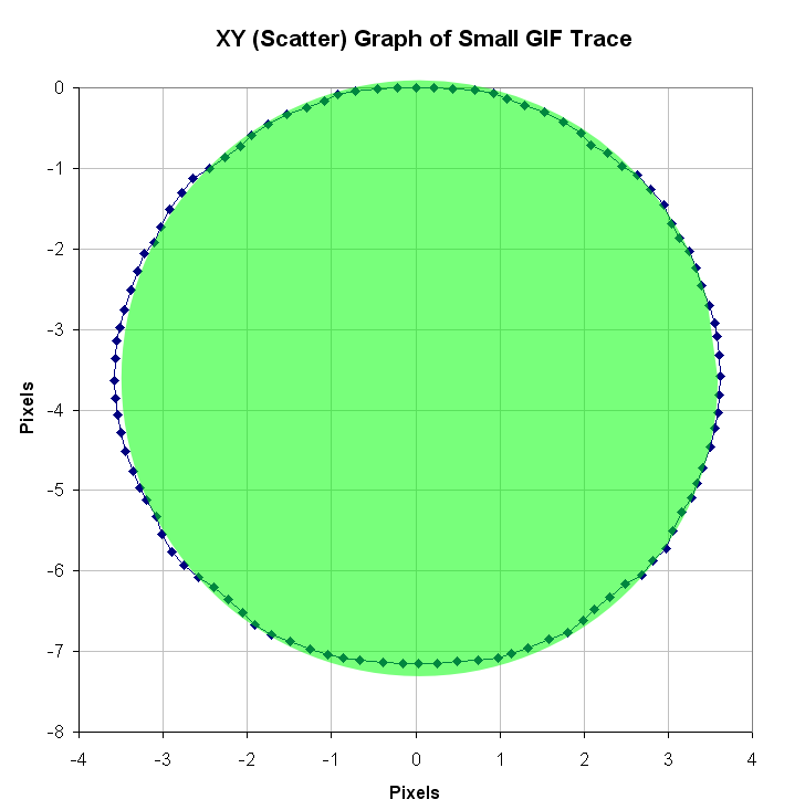
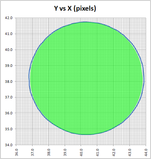
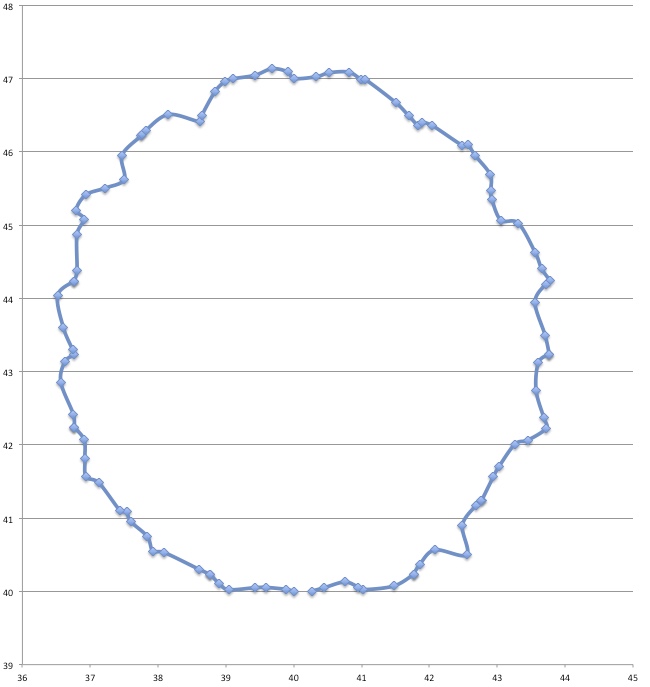
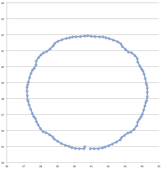
In between every frame, there is an infinite number of paths whatever point of measurement you are tracking could take from one pixel to the next. You can see this problem, I think, pretty clearly presented in the cookie cutter graphs produced by the raw data produced by what are being touted as the best measurement techniques in this thread. If your best data set needs to be corrected by a smoothing algorithm to even seem remotely plausible, it seems reasonable to me to assume there is a significant margin of error inherent in the measuring technique (error that the measurers are trying to correct with the smoothing).
Just eye balling the amount of smoothing applied to the data sets in the graphs, it seems to me there is a margin of error far in excess of 1% at play here, though I readily admit I do not know statistically the best way to conceptualize and approach precisely calculating that error given the particular measurement technique used here. Has anyone more familiar with the subpixel measurement techniques tried to calculate the margin of error?
Dimension would be ft/s^2. That translates to between 9,72109539648 m/s^2 and 9.90558620352 m/s^2.
Waaaaay too many decimals!
To my best determination, g is 9.805 m/s^2 at NYC latitude, sea level. So those values are 99.1% to 101.0% of g. That's the average for the 1.75 (?) seconds of the Phase 2 of the north wall descent, right?
Don't underestimate the ability to measure position to an accuracy way below pixel size. I have yet to see a solid mathematical approach to estimate systematical and random errors of the methods used, given the individual video quality. However, I remember mention of a 1/200th pixel resolution, and there seems to be confidence that accuracy is better than 1/10th of a pixel (oz and M_T - feel free to correct me, although exact numbers aren't important at this point to get the gist across).
Frame-to-frame there is of course noise. But when NIST can claim an R² = 0.9906 for their coarse method over a 1.75 (?) s time interval, why shouldn't it be possible to get the same or a better confidence level for a shorter interval (say, 0.5 s) when using a finer method - and a lower bound for a > g?
I'm not sure how it could be possible to determine so-called sub pixel accuracy without first knowing more precisely about the motion of the object being video taped. If you knew--independent of the pixel movement measurement mean--that an object was moving with a relatively constant acceleration, then I can imagine how you could do a bit of calculus and extrapolate subpixel accuracy for movement of the object across multiple pixels. But if you don't know the motion is smooth, I don't think you can get there without injecting a good amount of potential error into the calculations by way of assumption re the smoothness of the acceleration.
In between every frame, there is an infinite number of paths whatever point of measurement you are tracking could take from one pixel to the next. You can see this problem, I think, pretty clearly presented in the cookie cutter graphs produced by the raw data produced by what are being touted as the best measurement techniques in this thread. If your best data set needs to be corrected by a smoothing algorithm to even seem remotely plausible, it seems reasonable to me to assume there is a significant margin of error inherent in the measuring technique (error that the measurers are trying to correct with the smoothing).
Just eye balling the amount of smoothing applied to the data sets in the graphs, it seems to me there is a margin of error far in excess of 1% at play here, though I readily admit I do not know statistically the best way to conceptualize and approach precisely calculating that error given the particular measurement technique used here. Has anyone more familiar with the subpixel measurement techniques tried to calculate the margin of error?
Last edited by a moderator:


")

")