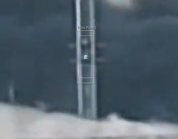
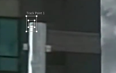
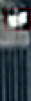
You specify areas to track by setting
track points in the Layer panel. Each track point contains a
feature region, a
search region, and an
attach point. A set of track points is a
tracker.
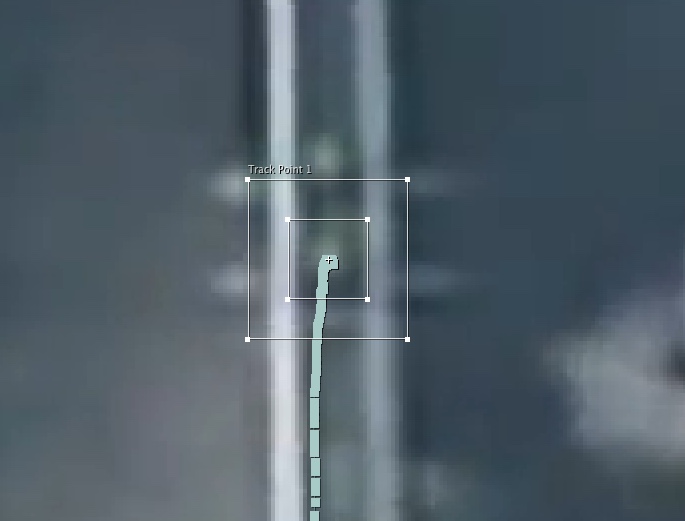
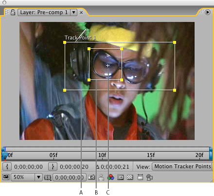
Layer panel with track point
A. Search region
B. Feature region
C. Attach point
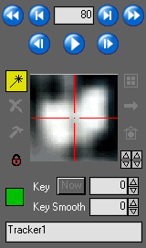
Feature region
The feature region defines the element in the layer to be tracked. The feature region should surround a distinct visual element, preferably one object in the real world. After Effects must be able to clearly identify the tracked feature throughout the duration of the track, despite changes in light, background, and angle.
Search region
The search region defines the area that After Effects will search to locate the tracked feature. The tracked feature needs to be distinct only within the search region, not within the entire frame. Confining the search to a small search region saves search time and makes the search process easier, but runs the risk of the tracked feature leaving the search region entirely between frames.
Attach point
The attach point designates the place of attachment for the
target —the layer or effect control point to synchronize with the moving feature in the tracked layer.


")