I was unnecessarily prickish in the last post. The points could be made without the jabs. It is difficult to ignore past history, and even more difficult to pretend that the current situation resembles a reasonable technical discussion.
Anyone who wants to believe that a 144" tall column of width 14-16" can turn two 90 degree bends and one 180 without fracture... I don't think I can fix that. I can try.
Even Szuladzinki's FEA shows fracture top and bottom, and an inability to keep the top segment plumb despite restraining forces, thus the sum of angles is not zero and it's more like two 70's and a 180. My point, very simply, was always that the fracture depicted was insufficient and did not reflect reality. If his sim has any credibility at all, it shows that fracture is indeed mandatory, even when you let the elements stretch to 5x their ductile limit and
survive. No argument has been made as to why the 20% ductile limit does not apply to his FEA. If it did, the column would've broke long before the final deformation depicted. Therefore it necessarily exaggerates residual capacity, probably greatly.
I'd like to proceed with the foundation set down above. I can expound on it if desired, but I'm going to work with the expression r = 2.5w relating minimum radius of curvature to a solid steel section of width w. The simple first approximation is to use differential arc lengths based on radius of curvature. Obviously hollow sections and I or H configurations can deform in such a way as to change the inner and outer radii, and more esoteric factors like transverse shear and so on are ignored. This is planar analysis and ignores the other horizontal dimension of the member. Deformations are assumed elastic without work hardening, even though this is patently unrealistic anywhere near the ductile limit. This is the absolute simplest model possible for bending deformation.
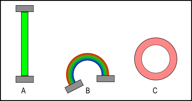
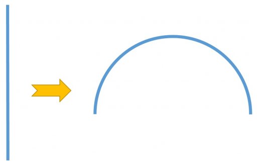
The figure labeled A represents a solid prismatic steel column with height:width ratio of 9:1 with fixed endpoints. If it were 144 inches high, it would be 16 inches wide. Figure B shows the same column deformed into a circular arc (constant radius of curvature) of just a little over 200 degrees end rotation. Note that column bowing is NOT a circular shape, and bending would not assume such a shape unless the ends were constrained as shown. But, being bent into this circular shape by constraint, the relations I derived above hold true (more or less).
The color shading represents the distribution of tensile and compressive strain in the member, with blue being compression, red tension, and green nominal (no distortion). The neutral axis, where the strain crosses from tension to compression, is shown as a dotted line. The radius of this axis from the center of the arc is set according to the relation for maximum elongation at the edge without fracture, 2.5 times the column width. This axis divides the cross section into regions of tension and compression, and the circumference at the outer edge is 1.2 times longer (the ductile limit) than the circumference at the neutral axis, which is at nominal length. For a 144" nominal length, the outside edge is stretched to 172.8 inches, and is on the verge of tensile fracture.
This circular arc is the tightest bend that can be done in this model without fracture. The end rotation is over 200 degrees, no problem. If the column were taller, it could go all the way around, 360. BUT, if the radius of curvature is decreased (circle gets smaller) while keeping the same width, the outer edge length will exceed 1.2 times nominal and fracture. Likewise, if the radius were kept constant but the width increased, same thing - fracture.
The column cannot be bent tighter and a wider column can't be bent this tight.
The geometry of this arrangement is independent of absolute size, it only depends on the proportion of width to radius of curvature. Therefore, this representation applies to a column or sheet of any size, theoretically. This leads to figure C, which is simply completing the circle. The purpose of this is to provide a template against which to judge the tightest bend possible. It's only necessary to scale the circle so that the width of the circular band matches the width of the column in question. In images which have roughly orthogonal perspective, the circle can overlay the column bend and show where the minimum radius of curvature is exceeded by a bend.
This model predicts fracture for members bending tighter than the curvature of the circle, and survival for those less tight. We'll see.