You are using an out of date browser. It may not display this or other websites correctly.
You should upgrade or use an alternative browser.
You should upgrade or use an alternative browser.
WTC: Rate of Fall (rate of crush)
- Thread starter George B
- Start date
OneWhiteEye
Senior Member
Well, at least I've heard of Abaqus, haha! Though never used it. Sounds like you've got tools at your disposal.
Let me explain a little more thoroughly the nature of my "model". It's a very gross first approximation based only on one fact: the stated ductile limit of steel. Ignoring all other relevant factors like work hardening, etc, this allows a prediction of when a solid member will fail under bending. Since a bend induces greater strain on the outside of a bend than the inside, there will come a point where the material has exceeded the ductile limit on the outside and will fracture.
My graphic ring depicts a maximum curvature which can be achieved according to this very simple model, given a solid material thickness. It can then be put up against photos (as close to orthogonal view as possible) and scaled to match the material thickness. If the bend radius is smaller than the circle, then it predicts fracture should have occurred. I'd guess it would generally predict fracture sooner than it actually occurs, but it is just the most crude guide.
If you wanted to set up something like this in an FEA modelling environment, just create a solid or hollow bar and apply follower forces to the ends, acting in the same direction, with the centermost elements constrained to remain in place (or alternately with an opposing force applied to the center in the opposite direction, but it would have to be variable and would almost certainly result in motion of the object as a whole). Another scenario would be a bar fixed at one end and a perpendicular force applied to the other end. Make sure fracture is on and see how far it bends before elements start to fail.
OneWhiteEye
Senior Member
Unfortunately, I don't know what COMSOL has in the way of follower forces, i.e. applied forces which remain in the same orientation with respect to the contact point on the member, but that's what would be necessary to maintain the tangential nature of a bending force. As the end moves under deformation, the force must maintain its angle against the end (or it drops to zero in the direction of interest once the bend hits 90 degrees). The second scenario - with one end fixed and one force on the other end - would be the best to produce the scenario in your diagram:I need to model kind of bending deformation of a solid rod to a semi-circle using COMSOL. Could you please help me with the loading types and constraints that I need to use for this model. Also, I need to consider my elastic-perfectly plastic with different yield stress at compression and tension. Is there any option for this in COMSOL?
I really appreciate your help.
Thanks,
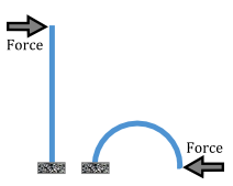
Constrained to motion in 2D... otherwise I suspect it'll just flop about due to instability, unless the rod is thick in the depth dimension (into the screen in this view).
OneWhiteEye
Senior Member
Damping is probably necessary, too.
OneWhiteEye
Senior Member
I've set up a 2D mass-spring model in Fydik2D which is a fully elastic ideal truss-like structure, fixed at the bottom, with a follower force applied to the top left corner. This is the system at the initial time:
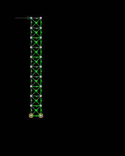
Rather thick, not like the thin rod you depict, and certainly not representative of a homogenous solid. All the same suitable for demonstrating some real-world deviations from the grossly simplified model.
First, though, let's keep this on topic in case your query is more a help-with-homework situation (in which case I'd advise you to hit one of the many engineering forums dedicated to FEA advice). We got to this point in the discussion by way of a referenced analysis which predicted a large resistive force in the collapse process. This analysis depends on findings of one of the authors' FEA work. There are a number of good reasons why it's unrealistic to expect these FEAs to be valid for the circumstances of the actual collapse, but there's a specific problem which renders the simulations entirely invalid over the latter stages of column deformation, and that is excessive ductility.
If fracture of members is not accounted for realistically, the estimate of force can be many times greater than should be expected and therefore the descent of the upper portion will be calculated to be much slower than actual, perhaps even arresting. That was the situation here, and the discussion then veered towards deciding how susceptible to fracture the load bearing members were. I offered the graphic ring as a rough rule of thumb as to how tightly a solid cross section could bend before the onset of fracture, and it turned out to do reasonably well when compared to actual steel recovered from the site.
Now, back to the diversion: What happens when the above mass-spring system simulation is run until static equlibrium is achieved (it's highly damped)?
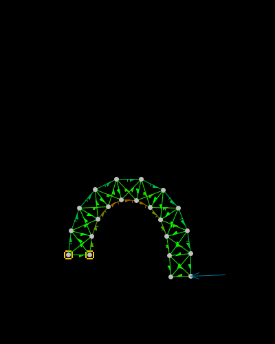
Not a perfect half-circle by any means, and there are a number of reasons why. Aside from that, it's pretty obvious that the structure has exceeded 20% elongation on the stretching side, so would've likely fractured, excluding any time-dependent material properties under deformation.

Rather thick, not like the thin rod you depict, and certainly not representative of a homogenous solid. All the same suitable for demonstrating some real-world deviations from the grossly simplified model.
First, though, let's keep this on topic in case your query is more a help-with-homework situation (in which case I'd advise you to hit one of the many engineering forums dedicated to FEA advice). We got to this point in the discussion by way of a referenced analysis which predicted a large resistive force in the collapse process. This analysis depends on findings of one of the authors' FEA work. There are a number of good reasons why it's unrealistic to expect these FEAs to be valid for the circumstances of the actual collapse, but there's a specific problem which renders the simulations entirely invalid over the latter stages of column deformation, and that is excessive ductility.
If fracture of members is not accounted for realistically, the estimate of force can be many times greater than should be expected and therefore the descent of the upper portion will be calculated to be much slower than actual, perhaps even arresting. That was the situation here, and the discussion then veered towards deciding how susceptible to fracture the load bearing members were. I offered the graphic ring as a rough rule of thumb as to how tightly a solid cross section could bend before the onset of fracture, and it turned out to do reasonably well when compared to actual steel recovered from the site.
Now, back to the diversion: What happens when the above mass-spring system simulation is run until static equlibrium is achieved (it's highly damped)?

Not a perfect half-circle by any means, and there are a number of reasons why. Aside from that, it's pretty obvious that the structure has exceeded 20% elongation on the stretching side, so would've likely fractured, excluding any time-dependent material properties under deformation.
OneWhiteEye
Senior Member
Here it is with structure half as wide, all other things equal (this time also showing rotational springs which were present before but hidden):
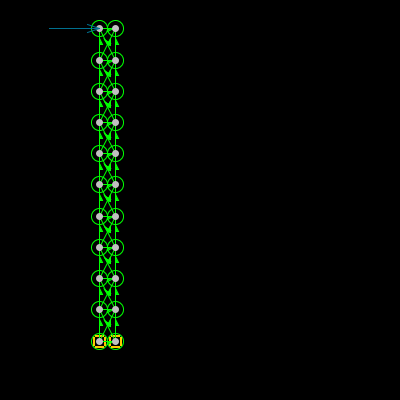
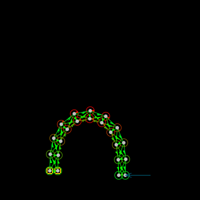
Better, but still an inverted 'U' rather than a semi-circle. This one is very close to 180 degrees rotation. I'd say the thinner your rod is, the closer it will be to ideal. I don't think it will ever turn out as a true semi-circle.


Better, but still an inverted 'U' rather than a semi-circle. This one is very close to 180 degrees rotation. I'd say the thinner your rod is, the closer it will be to ideal. I don't think it will ever turn out as a true semi-circle.
OneWhiteEye
Senior Member
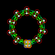
It can be coaxed into a full circle, more or less.

Major_Tom
Active Member
OneWhiteEye, the misalignment of the corner that you show is about four stories into the collapse and occurs after the upper section shortens by about four stories. The reason there was no deceleration is that the first stories to disintegrate where 98, 99, 100, and 101. This is quite clear in the video. Why would stories above the initiation floor disintegrate before anything is contacted below in a natural collapse?
OWE, this is early motion of the NW corner:

Followed by the other images you have already provided. There is quite a bit of visual evidence for lateral displacement over the first 1 story fall.
Followed by:
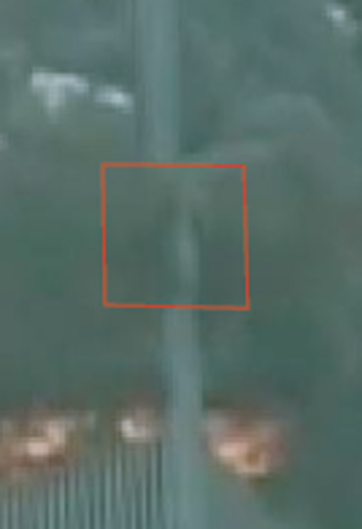
as you already did.
followed by:
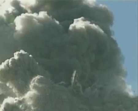
and

which is the lower portion of the west edge of the corner still standing.
A close-up of the large piece falling on the left side:
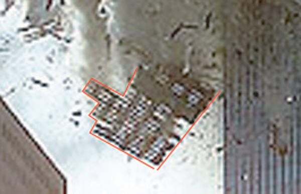
The whole NE corner ripped along the bottom, along the 98th floor.
Also the early eastward displacement of the antenna.
You can keep shooting that claim with a silver bullet or stab it with a wooden stake, but it just won't die!
>>>>>>>>>>>>
Sorry to interrupt your demonstration which is pretty cool.
Last edited:
OneWhiteEye
Senior Member
Hi, M_T. All good. Just dusting off an old toy.
psikeyhackr
Member
Not since high school . . . didn't take physics in college . . .
Newtonian physics in college works differently from Newtonian physics in high school.
psik
drommelsboef
Member
That shouldn't be psik. I've no idea what high school means but it isn't very high I assume then. Of course at college it's educated at a higher level. Differential equations, 5 times more complex math and things like the Langrange and Hamilton principle. The latter is something I only remember by name now...
Pure Newtonian physics is also not always very easy. Some simple looking problems can be very complex.
Pure Newtonian physics is also not always very easy. Some simple looking problems can be very complex.
drommelsboef
Member
An open question to Mick. What's the point of locking threads? Could you write down the reason. I'm relatively new here but it seems they are often closed.
When threads wander off topic and/or no new, relevant information is being offered it can be locked.An open question to Mick. What's the point of locking threads? Could you write down the reason. I'm relatively new here but it seems they are often closed.
Less than 1% of threads are closed. They get closed when they go off topic or stray too far from the posting guidelines.An open question to Mick. What's the point of locking threads? Could you write down the reason. I'm relatively new here but it seems they are often closed.
Similar threads
- Replies
- 42
- Views
- 4K
- Replies
- 12
- Views
- 2K
- Replies
- 14
- Views
- 4K
- Replies
- 243
- Views
- 30K
- Replies
- 17
- Views
- 5K
