Pre-Failure Oroville Dam Spillway Historical Images

Status
Not open for further replies.

Mick West

Administrator
Staff member
Note
This thread was split from:
https://www.metabunk.org/oroville-dam-spillway-failure.t8381/
It is a focussed thread dealing just with finding and analyzing pre-failure photos of the damage area to see if there are clues as to what happened
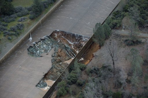

"Obviously something has happened that we didn't expect to happen," said Kevin Dossey, a senior engineer with the Department of Water Resources. "I don't think anybody who is in the inspection team or the repair team would say that more should have been done because there wasn't more evidence that more needed to be done."

2013 photo_1486774392447_5834027_ver1.0_640_360.jpg
http://www.krcrtv.com/news/local/bu...mage-surfaces-supervisor-blames-dwr/325934917
Content from External Source

Hard to line up, but it looks like that damage is slightly above where the hole first formed.
20170210-223837-9hube.jpg
 
Last edited:
some more commentary by Senior Civil engineer of dwr Dossey, full 2013 pic with credit, ..but no link to the inspection reports.

[edit add: links to available inspection reports located bottom of this article http://www.chicoer.com/article/NA/20170210/NEWS/170219971#]

http://sacramento.cbslocal.com/2017...how-oroville-dam-spillway-previously-patched/


“There were some patches needed and so we made repairs and everything checked out,” said Kevin Dossey, a Senior Civil Engineer with the Department of Water Resources. “It looked like it would be able to hold, be able to pass water.”

Dossey says this sort of thing is routine.

“It’s common for spillways to develop a void because of the drainage systems under them,” said Dossey.
Content from External Source
The inspection reports in the last 3 years check out. Only referencing previous patchwork. By all indications the spillway was solid
Content from External Source
c4lpkywueaaezj7.jpg

video of the interviews, and at 2:22 reporter says they viewed the 2014 and 2015 inspection reports and are waiting to receive the 2013 reports to get details on possible erosion issues mentioned by Dossey.
https://www.msn.com/en-us/news/us/m...le-dam-spillway-previously-patched/vp-AAmPcKB
 
Last edited:
Here are the inspection and damage photos better registered. It does appear that the failure is related to the area of prior concern.
Oroville Spillway.jpg
 
Last edited by a moderator:
It does appear that the failure is related to the area of prior concern.
i think youre off by a slab (although i dont know how long the slabs are so not sure it matters all that much)
whiteline.JPG
 

Attachments

  • KG_oro_spillway_damage_9970.jpg
    KG_oro_spillway_damage_9970.jpg
    267.5 KB · Views: 559
Here are the inspection and damage photos better registered. It does appear that the failure is related to the area of prior concern.
Oroville Spillway.jpg

I sent my engineer friend this post and this is his response:
Man! What a good source. Excellent if fact. I enjoyed it, got me thinking.
We Hams, we know about standing waves? These would be Long wave, subsonic waves. Meters in length.
The start of the spillway in the feed, the power terminator is the speed bumps at the bottom. There's Kilowatt, (Megawatts) of acoustical energy emitted as noise.
To examine the entire spillway, it looks like a Transmittion line. Energy feed, Energy terminator, containing a lot of Raw power in between.
Frankly, I think the failure was caused by resonance. Something not planned for? Not cheap construction, or some terrorists. Time will tell? Hope it wasn't just a big leak.
I know acoustical wave travel backwards in a flowing column of water. If they are strong enough, they will reverse the flow, and I can prove this. I can well imagine the vibrations building up in a rigid flat plate until it breaks. I'm sure, they must have a seismometer there.
Wonder what seismic data, during the course of failure, would revile? Bandwidth of the detectors?
Super link. Sign up? Mick West sounds grounded.
 
Last edited by a moderator:
I would like to know if the engineers inspecting the damage on the spillway evaluate the type of concrete used to build the dam?
the dam? the federal government according to articles (which are all over the internet) inspects the actual dam every 5 years. I imagine inspecting the concrete is part of inspecting. you can look at the inspection reports i linked in a previous post and google "FEMA dam safety" to read about dam inspection protocols. maybe google "concrete maintenance".

[edit: hmm this link says both feds and state inspect every year.
He also explained that the dam gets yearly inspections from both state and federal inspectors. According to the July 2015 inspection report, "The FCO structure appeared to be satisfactory with no visible concrete or structural deficiencies."
Content from External Source
A federal inspection in 2010 concluded that Oroville Dam, the tallest in the nation, needed a comprehensive earthquake safety assessment, but no significant flaws were found in the dam itself. The inspection was conducted by consultants working for the Federal Energy Regulatory Commission, which oversees hydroelectric dams in the United States.

Read more here: http://www.sacbee.com/news/state/california/water-and-drought/article131941279.html#storylink=cpy
Content from External Source
here's a fun old video of the construction 50 years ago.

Source: https://www.youtube.com/watch?v=p_5udzKfLQM
 
Last edited:
Last report I reviewed was 2010, so do you know where the 2015 report might be located? Thanks for the video!
 
Very interesting comparison. A minor problem gave the water something of a "handle" with which to unzip the concrete. Once the hole was open, it spread rapidly.
 
This site (link) overlays "before and after" orthorectified aerial photos of both spillways, full length, and presents them with a slider enabling convenient examination of their differences. Well Done.

Edit: And I see that Mick just inserted the same slider tool above, on a close-up of the full photo.
 
A photo of the spillway Jan 27, 2017, failure was on Feb 8, just 13 days later. There might be some clues here
https://mng-chico.smugmug.com/Oroville-Week-of-1-30-2017/i-sZJBSXt/A

This spot is the top line of the original hole.
20170216-132317-vyiah.jpg

Move slider here to compare.
[compare]
View attachment 24731
View attachment 24733

[/compare]
First post, but have been lurking (and learning a LOT of fascinating info) for a couple weeks now.

In regards to your post and the photos above - I'd be equally concerned about the dry areas below certain joints between slabs. While some water (at a VERY low speed) might just divert across a joint for a few inches, it's unlikely for it to vanish like that, right? I mean many areas are just DRY.

Is there a wider view of the spillway at a low flow rate like that which shows any other dry areas?
 
Here's the spillway on Sept 5, 2014. This is a few hundred feet above the actual damage section. Note a variety of cracks and repairs
20170216-141208-mgzp0.jpg

Here are similar cracks just below the hole

20170216-142135-yljzh.jpg
 
Last edited:
Another pic from the previous week:
https://mng-chico.smugmug.com/Storm-Aftermath/i-cdm4L2c/A
20170216-135932-rvyvp.jpg

However you can't make out any detail in that region because of the noisy shadow.

That 'noisy shadow' is from adjacent trees. I've been thinking about that for the last couple of hours and had tried to find the 2013 photos, but the one's you've posted are much better.

Tree roots.

Anyone who has a concrete driveway with adjacent trees knows what eventually happens. You can see that the cracks were patched with some type of grout. Perhaps the roots, if that is indeed the cause, grew to the point of causing the slab to heave? And could the underlying root system given any infiltrating water a channel to travel along and allowed washout to occur?
 
Found this while digging around, it's a postcard of the construction. Is it me or does it look like 2 sections split with a line in the neighborhood of the initial compromise last week? I can't tell exactly where the line here compared to the compromise last week, but it looks close. Did they pour in these stages as it looks like the non-poured up top is about as long as the bottom 2 sections? It's not a great image so hard to tell. Any other thoughts? Thank you

s-l1600.jpg
 
The google Earth image from 4/14/2015 shows a lot of patches on the join at the top of the original failed area.
20170217-164550-u69q9.jpg
They actually look like rectangular patches, like someone sawed out spalling concrete to make a better patch. Like
20170217-165356-15g5e.jpg
You can verify this is the join by the pattern of white repairs on the join above.
20170217-164842-x0s5c.jpg
 
Not sure if this came up before, but the google Earth image from 4/14/2015 shows a lot of patches on the join at the top of the original failed area.
20170217-164550-u69q9.jpg

Nice find. There are two other areas with similar appearance in that image. Check out where the next one upstream is:

OroSpillwayPatchesNearPylons.jpg


That's very close to if not coincident with the current upstream failure progress.


The other place you find these is about 500' down from the gates:

OroSpillwayPatchesNearGates.jpg
 
Much of the rock missing at the base of the spillway in this photo,light gray areas missing.jpg

is of a lighter gray outlined in green in the postcard photo. Also note the strange darker area of the spillway right where the blowout occurred (circled in red). light gray areas anotated.jpg
 
From Micks 2012 pic above ... can seen the left side (looking at pic) drain appears to have been weal flow and/or inoperative since at least 2007 ... we can see the appx top of the start of the damage area and some cavitation occurring over it.

And on right we can see what the drain pipe looks like (this would be one below the inoperative one) ... that it comes from under slab

A guess is maybe water is supplied to these drain pipes when spillway flow is initiated - perhaps a pipe along each side of spillway that runs from top ... and the discharge topside creates a negative pressure in the drain pipes to draw water out of the subsurface?

If that is the case - that these pipes are charged with water from above - then a non operating pipe could be broken and leaking that water under the panels

Credence is led to the theory these drain ports and charged with water by the fact that the large blowout in sidewall and resultant erosion killed flow from all drains below it. Which is also supported by fact a small wall breach initially did not kill drains on left side, but when a larger wall breach occurred the lower drains did stop working ...

SpillwayMain-Noflowdrains2012.jpg
 
The TerraServer site has a series of higher resolution images of the area:
https://www.terraserver.com/view?utf8=✓&search_text=39.53986, -121.49537&searchLat=39.53976&searchLng=-121.49537&lat=&lng=&bbox=&center=
20170218-074455-4wmhi.jpg

The patches/damage show up in a variety of photos
20170218-074543-nm517.jpg

But of particular interest is this one labeled 2016-05-02
20170218-074913-hhytq.jpg

20170218-074913-hhytq.jpg

Appears to show some turbulence at the spot where the damage occurred.

This type of turbulence also occurs in one other spot near the bottom.
20170218-075219-hqeqg.jpg

Like the hole area, this lower turbulence area also shows a quite large repair
20170218-075744-qgwfo.jpg

This lower damaged area was still visible after the upper hole formed, and was visible during the first stoppage:

20170218-081207-cwli9.jpg

20170218-080806-t2dph.jpg
 
Last edited:
This type of turbulence also occurs in one other spot near the bottom.
20170218-075219-hqeqg.jpg

Amazing find. Such turbulent areas (spalled concrete or lost patches of previous spalls) lend creedence to the cavitation theory.

http://www.chicoer.com/general-news...possible-culprit-in-oroville-spillway-failure

Cavitation could quickly enlarge these imperfections. I would point out that cavitation might not be the root cause. One has to ask why these spots require work in the first place. The drains / poor rock being discussed here could still be the ultimate root cause.

Inspecting the spillway "at a distance" in 2016 and 2015 looks bad in light of this photo.
https://www.metabunk.org/oroville-dam-spillway-failure.t8381/page-23#post-201094
 
Great new thread:

If anyone with access to the CA DWR site could download full versions of these (my account still has not approved):

http://pixel-ca-dwr.photoshelter.co...gQ/NH-Oroville-86-Flood-6590-2-02-21-1986-jpg

http://pixel-ca-dwr.photoshelter.co...GnbdY/Oroville-86-Flood-6590-4-02-21-1986-jpg

and post a closeup of the drain outlets, it would be a comparison of drain flow then vs. now. This is the only event I know of where spillway flows were higher than Feb 2017. These photos show a 150,000 cfs flow.

https://www.metabunk.org/oroville-dam-spillway-failure.t8381/page-24#post-201208

These might show whether drain flow has increased over time.

Edit: FWIW, here is the best I can do w/o the ability to download the full res pic:

upload_2017-2-18_11-11-59.png

Drains are clearly flowing pretty good, but at a what looks like less flow than a few days ago. This with 50% more flow in the spillway.
 
Last edited:
Much of the rock missing at the base of the spillway in this photo,light gray areas missing.jpg

is of a lighter gray outlined in green in the postcard photo. Also note the strange darker area of the spillway right where the blowout occurred (circled in red). light gray areas anotated.jpg

The bare rock at the end of the spillway indicates considerable erosion; earlier photos show this area as well covered. I gather then that the spillway termination is not protecting the river and channel as it should. Reconstruction of the spillway should include upgraded exit to disperse the energy of the water flow.
 
the other thing i was wondering about (although its hard to place things exactly due to camera perspectives and angles).. doesnt this tree look particularly close (and big ie big root system) to the spillway. this photo is 2005...
i remember one area with a hole up by the weir, in one of the inspection reports (aug 2016) they mentioned 'remove the fig tree'. ??

Yes. Roots from that tree could potentially go under the spillway wall. From FEMA:

https://www.fema.gov/media-library-...y-data/20130726-1502-20490-9679/fema_l263.txt


Located on dams, trees and other
woody vegetation that would otherwise bring charm
to a city park could interfere with adequate inspection
or safe operation of dams, or even cause dam failure.

(snip)

. The decaying roots of dying vegetation create a
seepage path in the embankment for stored water
or wastewater. This path can lead to internal erosion
(piping) of the embankment.

(snip)

. Roots can penetrate existing cracks and joints in
the foundation rock and embankment, potentially
leading to internal erosion and seepage.
Content from External Source
These words apply to the spillway too. The roots can shorten the distance between the source of high flow in the spillway to an exit point.

I would add this as #4 to this list:

https://www.metabunk.org/oroville-dam-spillway-failure.t8381/page-22#post-201017

Which came first, the erosion of the bank outside the wall or did failure of the spillway slab force water under the wall, or was it water splash? Could a tree root have made it easier to scour under the wall? Probably.
 
The bare rock at the end of the spillway indicates considerable erosion; earlier photos show this area as well covered. I gather then that the spillway termination is not protecting the river and channel as it should. Reconstruction of the spillway should include upgraded exit to disperse the energy of the water flow.

A bit off topic here, but from the historical images the flow pattern over the rocks not that different in 1969. I suspect the first few large flows simply washed away the loose rock, and it has been pretty much unchanged for the last 40 years.
20170218-095844-u9v5h.jpg
 
Status
Not open for further replies.
Back
Top