Mosul "Sphere"

CORRECTION: I found a video where a camera crew was allowed to film inside the cockpit during a mission in Afghanistan...https://youtu.be/xQDmt4CiY2I

System is called a L3Harris Wescam MX-25D. Very similar capabilities to the FLIR system. Bottom line, very sharp imaging. Here's the tech sheet.

This is correct. The MX-25 is the larger variant of the MX-15 that was used to capture the Aguadilla 'UAP' (the number refers to the turret diameter in inches. Bigger turret = better optics).
 
While searching for information on the MC-12 Liberty aircraft I found this link: https://www.beale.af.mil/News/Photos/igphoto/2000107177/mediaid/296321/ which indicates the use of the WESCAM MX-15 EO/IR system on that plane.

I found a link to the MX-15 system here: https://www.l3harris.com/all-capabilities/wescam-mx-15-air-surveillance-and-reconnaissance also from L3 Harris.

Of course neither tell us that that was the particular combination in use for the still in question but I did find confirmation that the MC-12s were at least initially equipped with the MX-15 via this link: https://www.airforce-technology.com/projects/mc-liberty/
Good work! It's from 2012 so may have been updated to the newer system within 4 years time, but looking at the technical data of each, the capabilities and resolution are very similar...it appears the biggest difference is that one is capable of laser targeting designation for guided munitions and the other is not.
 

Attachments

  • Screenshot_20230127-081504.png
    Screenshot_20230127-081504.png
    1.4 MB · Views: 82
Good work! It's from 2012 so may have been updated to the newer system within 4 years time, but looking at the technical data of each, the capabilities and resolution are very similar...it appears the biggest difference is that one is capable of laser targeting designation for guided munitions and the other is not.
Not necessarily. Each turret in the MX range can be made with options that are chosen by the purchasing agency and depend upon their operational need.
 
so we want the specs from a wescam mx-15?
It was the MX-25 that was used in this incident. The specs and performance are largely the same between them, with the some better optics and higher resolutions available in the larger ones.
 
Not necessarily. Each turret in the MX range can be made with options that are chosen by the purchasing agency and depend upon their operational need.
Sorry, I only saw laser range finding and laser illumination for low light in the sheet, but nothing showing that it's certified for NATO targeting code standards.
 
how do we know this?
Yeah, I seemed to have missed this too. We have a claim about what type of aircraft was used and what kind of camera system it had on it, but I can't seem to find where that came from. Flarky detailed the flight path, but not what type of aircraft. It's maybe not that important but is it considered to be an USAF MC-12 because the photo identifies what type of camera is being used and that camera system is used on an MC-12 and that's what the USAF would likely use in that situation, or do we know for sure that's what was used.
 
Yeah, I seemed to have missed this too. We have a claim about what type of aircraft was used and what kind of camera system it had on it, but I can't seem to find where that came from. Flarky detailed the flight path, but not what type of aircraft. It's maybe not that important but is it considered to be an USAF MC-12 because the photo identifies what type of camera is being used and that camera system is used on an MC-12 and that's what the USAF would likely use in that situation, or do we know for sure that's what was used.
The Black Vault says its an MC-12 , but that information comes from Jeremy Corbell's Instagram

https://www.theblackvault.com/docum...uap-published-by-jeremy-corbell-george-knapp/

https://www.instagram.com/jeremycorbell/

Post:
Source: https://www.instagram.com/p/CnylcdcOaXF/
 
It certainly looks rather like it, but the big problem is focus. it seems implausible that a drop would be that much in focus when zoomed in so much and focussed on the background miles away (essentially at infinity)
It doesn't have to be a liquid drop. A tiny ice crystal or a speck of dust on the outside glass might have caught the sunlight and reflected it to the camera, producing a round bokeh. Something like on one of my old aerial photos below (full photo attached). Screenshot 2023-01-27 at 17.19.35.png
 

Attachments

  • P1070378.jpeg
    P1070378.jpeg
    453.7 KB · Views: 89
Last edited:
Definitely an MX series turret though.
yea the screen display matches all the mxs. (there's even an mx-20 apparently). i thought maybe only the mx-25 has a pink font option though... kinda hard to imagine older versions having a pink font option.
 
@jackfrostvc

I have been able to calculate the aircraft position

1674659013156.png

Range to Aircraft position is 5.8 km on a bearing of 282 from position 36.32755 43.18434

Using the Haversine formula...

https://www.movable-type.co.uk/scripts/latlong.html

1674658571499.png
Aircraft position is DMS 36° 20′ 18″ N, 043° 07′ 16″ E Altitude 19400 ft,

= 36.3383 43.1208

https://www.latlong.net/c/?lat=36.33833333&long=43.12083333

Edit 1 - corrected the aircraft alt to be Height above ground ( ie 19403 -720 = 18683 ft)
Edit 2 - corrected faulty maths
If you estimate the size of the ground area in view of the camera, you can determine its angular FOV. From that you can determine the angular size of the object and make a distance vs physical size plot (or an altitude vs physical size plot) of the object to see if the combination of size and altitude/distance would fit a balloon, or a water droplet that bounced off from a sprinkler (the sidewalk seems to have wet patches), or ...
I don't know if the depth od focus of the camera is known; this could be used to have a idea of feasible distances from the camera.
 
@Itsme

Not sure if I can agree. The angular size of the ground is not the same as our "ufo", they are at different object distances wrt the camera lens. We cannot determine from the picture alone, the actual size of the droplet/ufo/etc, I believe.
 
@Itsme

Not sure if I can agree. The angular size of the ground is not the same as our "ufo", they are at different object distances wrt the camera lens. We cannot determine from the picture alone, the actual size of the droplet/ufo/etc, I believe.
Yes, I agree. I think you misunderstood my post. You can determine the angular size of the object. This gives you a relation between distance and physical size. A mylar balloon, for instance has a typical size. Fill in this size in the relation between size and distance, and you'll get an estimate of its distance to the camera. Same for a water droplet. You can then at least assess whether the estimated distance falls within the range where the camera image should be reasonably sharp. Maybe some of the hypotheses can be ruled out this way.
 
i still think it's something on the ground (do they have city water pipes?) a deep puddle as none of their roads are actually paved. but.... they were bombing the 15th...no idea what time they bombed. what does a dropped bomb look like from above?

Article:
It works across services, meaning the Liberty can guide bombs deployed by the U.S. Army and Navy.


Article:
Near Mosul, four strikes struck an ISIL tactical unit, 14 ISIL modular oil refineries, and two ISIL crude oil stills and destroyed an ISIL assembly area and 10 ISIL boats


are plane huds set to iraq time? if the press release says we bombed april 15th is that april 16th in iraq?

?
 
Last edited:
i still think it's something on the ground
Is that compatible with this statement?
The video is 4 seconds long. The UAP is seen “moving with purpose” in a lateral direction across the video (south to north). The “orb” UAP is visible for approximately 1 second – as it moves through frame.
(Source: Corbell's Instagram)
 
Last edited:
Is that comatible with this statement?
The video is 4 seconds long. The UAP is seen “moving with purpose” in a lateral direction across the video (south to north). The “orb” UAP is visible for approximately 1 second – as it moves through frame.
(Source: Corbell's Instagram)
I don't believe Jeremy Corbell. so i only have the screengrab to go by. and the 2019 satellite grab is definitely something on the ground.
1674561699432.png
but still if Corbell didnt know the location he would assume North by the camera display, which would just be something moving up the road. (one of those odd shaped IRaq patrol vehicles?). or a parallex thing caused by the plane moving one way and the camera a different way. we'd need to see the video.

there's all sorts of weird shapes seen on that street over the years in Google Earth:

317.png
519.png


"on the ground" is just my opinion from the still shot, but googling the area a bit last night i see the fighting had started in mosul at that point, so i'm not totally discounting something airborne (drone, projectile as ISIS destroyed the historical stuff they were targeting that day, etc)
 
It doesn't have to be a liquid drop. A tiny ice crystal or a speck of dust on the outside glass might have caught the sunlight and reflected it to the camera, producing a round bokeh. Something like on one of my old aerial photos below (full photo attached). Screenshot 2023-01-27 at 17.19.35.png
I agree with this. Whatever we are seeing is not an image of something on the camera lens.

While using a long focal length lens focused on the ground, even something on the glass shield of the aircraft wouldn't be caught as an in-focus image, or any kind of image at all.

At the age of 15 I learned it was perfectly possible to shoot through a chain link fence... if you use a fairly long focal length lens and have the camera up against the fence. Why? Because the fence is so out of focus that the light reflected by it is spread across the frame.

Actual photo shot through chain link fence backstop. (Not mine)

00TDuL-130215584.jpg.1b0d8ed8d4545e954ebb150f88f8565a.jpg


Consider a Newtonian telescope.


Reflector_Diagram_9a99023b-651d-4295-b332-66aa0fd6320f_1024x1024.jpg

It has a secondary mirror in front of the primary mirror. Yet we don't see an image of that mirror or the spider when looking through the telescope.

download (4).jpg
The spider holds the secondary mirror

Those things are so out of focus that the light is spread across the primary mirror. What does happen is that the contrast and brightness of the image are reduced.

On the other hand we can see an optical effect caused by the spider.

https://esahubble.org/about/faq/#5
The crosses, known as diffraction spikes, are caused by the light's path being disturbed slightly as it passes by the cross-shaped struts that support the telescope's secondary mirror. It is only noticeable for bright objects where a lot of light is concentrated on one spot, such as stars.

image_3665e-Hen-2-80.jpg


If the Mosul Sphere image is the result of something on the glass shield of the aircraft, what we're seeing is the result of the light being disturbed by the thing, not an image of the thing. An optical effect.

I think a dried water spot is a good candidate.

DURATION - The video is 4 seconds long. The UAP is seen “moving with purpose” in a lateral direction across the video (south to north). The “orb” UAP is visible for approximately 1 second - as it moves through frame.

The transitory nature of the effect - 4 seconds - can be explained by the angles changing slightly.

The movement: The "with purpose" part is a dangerous and typical Ufologist assumption. But does the movement stay exactly fixed within the frame? We don't know. But that would support it being something on the glass.
 
Last edited:
@Z.W. Wolf

I agree with your comments, it is in my view also impossible for a long focal telescope to have an object in (rather) focus, that is that close. It is related to the f/#, and the hyperfocal distance is usually tens of meters for systems of f/11 and up.
 
Does that mean Corbell has seen or has the video?
Has he mentioned he has it or has seen it?
I'm not sure. In the video with George Knapp he mentions it at ~01:24 (the whole video is only 3:32 mins., so it is not much of an effort watching from the beginning to the end).
It's on YouTube and on The Black Vault, below John Greenewald's comment, that is worth watching, too:
https://www.theblackvault.com/docum...uap-published-by-jeremy-corbell-george-knapp/

John has a suspicion who leaked the topic to Corbell, yet he doesn't want to speculate too much. He has submitted a request to the Pentagon, so he shall keep us updated if there are any news from that side.
 
Is there a reason not to believe what he is saying
his hair is too shiny and his skin too exfoliated. I think he is alien trying to distract us from actual extraterrestrial activity. (plus he likely sat on this photo, according to Greenwald, for quite a while and only pulled it out when he needed free advertising for his new show).
 
I think we've been too naïve and old-fashioned. I've been looking at info on the Internet specific to modern low altitude digital aerial photography.

I think this is an artifact that was produced by the radiometric correction of images.

Radiometric correction is also used for satellite images and so on.

If I'm getting this right, this is a method for correcting the brightness of objects in the entire image simultaneously.

But radiometric correction of images is an evolving technology, and can be haywired by the reflectance effects from objects at the anti-solar point. (And maybe Rayleigh scattering caused by atmospheric haze in the anti-solar point of the camera in each individual frame? I'm not sure.)

This can produce an artifact known as a hotspot due to bidirectional reflectance effects.

Now bear with me, because this image was not at the camera's anti-solar point, but I think this is all apropos because it demonstrates that radiometric correction can be haywired by unexpected reflectance effects. Especially since this is an evolving method, and this image may be the result of a particular method used only in the 2016 timeframe.


What's bidirectional reflectance? It's not just about what things look like at the anti-solar point of an observer.

https://snr.unl.edu/agmet/brdf/brdf-definition.asp
The reflectance from a surface depends upon the direction of incident radiation (and its characteristics), the surface radiative properties and the direction from which the surface is being viewed.
In vegetative canopies, the distribution of leaves, the amount of leaf material and viewed fraction of leaf material in the direction of the sun and view affect the reflectance.

https://www.umb.edu/spectralmass/terra_aqua_modis/modis
The BRDF is the "Bidirectional Reflectance Distribution Function." It gives the reflectance of a target as a function of illumination geometry and viewing geometry. The BRDF depends on wavelength and is determined by the structural and optical properties of the surface, such as shadow-casting, multiple scattering, mutual shadowing, transmission, reflection, absorption, and emission by surface elements, facet orientation distribution, and facet density.


What's the anti-solar point?
https://personal.math.ubc.ca/~cass/courses/m309-03a/m309-projects/endersby/Antisolarpoint.html

If we look at the ground on a sunny day, the shadow of our head marks the point called the antisolar point, 180° away from the sun. If the sun is in the sky, the antisolar point is below the horizon. If the sun has set, the antisolar point is above the horizon.

antisolarpoint (1).gif
https://www.researchgate.net/figure...te-sensing-a-saturated-image-b_fig5_270726348
The recent development and proliferation of unmanned aircraft systems (UASs) has made it possible to examine environmental processes and changes occurring at spatial and temporal scales that would be difficult or impossible to detect using conventional remote sensing platforms. This review article highlights new developments in UAS-based remote sensing, focusing mainly on small UASs (<25 kg). Because this class is generally less expensive and more versatile than larger systems the use of small UASs for civil, commercial, and scientific applications is expected to expand considerably in the future. To highlight different environmental applications, we provide an overview of recent progress in remote sensing with small UASs, including photogrammetry, multispectral and hyperspectral imaging, thermal, and synthetic aperture radar and LiDAR. We also draw on the literature and our own research experience to identify some key research challenges, including limitations of the current generation of platforms and sensors, and the development of optimal methodologies for processing and analysis.
Common-image-artifacts-and-distortion-from-UAV-remote-sensing-a-saturated-image-b (1).png


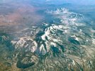
(f) hotspots on mosaic due to bidirectional reflectance effects
Another commonly seen illumination effect is the presence of image hotspots, where a bright spot appears in the image (Fig. 6). These are due to the effects of bidirectional reflectance, which is dependent on the relative position of the image sensor and the sun (Hakala et al. 2010; Grenzdörffer and Niemeyer 2011; Laliberte et al. 2011). Hotspots occur at the antisolar point, which is the point where the line defined by the sensor position and the sun intersects with the ground.


Quality Assessment of the Bidirectional Reflectance Distribution Function for NIR Imagery Sequences from UAV​

Received: 30 July 2018 / Revised: 19 August 2018 / Accepted: 21 August 2018 / Published: 24 August 2018
https://www.mdpi.com/2072-4292/10/9/1348

Imaging from low altitudes is nowadays commonly used in remote sensing and photogrammetry. More and more often, in addition to acquiring images in the visible range, images in other spectral ranges, e.g., near infrared (NIR), are also recorded. During low-altitude photogrammetric studies, small-format images of large coverage along and across the flight route are acquired that provide information about the imaged objects. The novelty presented in this research is the use of the modified method of the dark-object subtraction technique correction with a modified Walthall’s model for correction of images obtained from a low altitude. The basic versions of these models have often been used to radiometric correction of satellite imagery and classic aerial images. However, with the increasing popularity of imaging from low altitude (in particular in the NIR range), it has also become necessary to perform radiometric correction for this type of images. The radiometric correction of images acquired from low altitudes is important from the point of view of eliminating disturbances which might reduce the capabilities of image interpretation. The radiometric correction of images acquired from low altitudes should take into account the influence of the atmosphere but also the geometry of illumination, which is described by the bidirectional reflectance distribution function (BRDF). This paper presents a method of radiometric correction for unmanned aerial vehicle (UAV) NIR images.

BTW is this a NIR image?
Mosul Orb No Watermark. png.png
Don't know

Was this this taken from a UAV? Don't know.

I'm just trying to convey the message that processing methods have been evolving.


Now then: Could this be an artifact produced by radiometric correction of images due to a specular reflection of the Sun from an object on the ground?

As pointed out previously in this thread, this could not be a specular reflection of the Sun from the surface of ponding water. The angles aren't right for that.

But it could be a reflection from an irregular object. It doesn't have to be a car or highly reflective. It might not even be something producing a specular reflection, but a bright diffuse reflection. Just something producing an unexpected reflectance effect.

Even, perhaps a dried water spot on a glass camera shield?

I think this is all evidence that this is simply a processing artifact that is unique to most of us, because it was caused by a new processing method.

Or perhaps by a method that was only briefly used in the 2016 timeframe.


Same source as above, from 2018
Simple Dark Pixel Subtraction:
–the model takes into account the shift of histograms in the specific channels depending on the angle of image acquisition [22]. It is caused by reflected light from outside the field of view of the sensor, which reaches the field of view of the sensor even if the ground reflection coefficient is equal to zero.

Modified Chavez Method: In some cases when the image content was not homogeneous but it contained urban areas, forests or flat areas, excessive correction was observed in the RED and NIR channels [23]. In such cases, the λ-κ rule was proposed for the atmospherically scattered radiance. The value of the κ coefficient was in the range from 0.5 for haze in the atmosphere to 4.0 for a clear Rayleigh-type atmosphere. Due to the fact that the blue band shift represents the greatest impact of the atmosphere, it may be expected that the values determined for the channel will be the most accurate ones. The determined value of the shift (calibrated) enables the determination of the value of κ. The greater the shift in the DN values of the pixels, the thicker the haze of the atmosphere. Moreover, the κ-coefficient rule depends on the altitude of flight. In the case of images acquired from low altitudes, the useful range of altitudes will usually be within 100 to 300 m. The values of the shift for other channels including NIR.

We can't identify this unique kind of artifact, so it's mysterious.

The typical UFOlogist leap of logic is that if it's mysterious it must be otherworldly, or supernatural, or extradimensional, or whatever you want to say.
 
Last edited:
I'm aware that the aircraft was allegedly identified as a twin turbo-prop airplane, but considering the source, who knows?

Also doesn't rule out a processing artifact.

What does the 728FTt mean? Ditto 19403 and 26683?Mosul Orb No Watermark. png.png

26,683 - 19,403 = 7,280 wut?

Mosul altitude above sea level is 732.
 
Last edited:
I don't think he claims to have the video, just the still. From his podcast:
https://www.weaponizedpodcast.com/
Corbell:

Yeah, this is an image taken over northern Iraq. And you know, this is fine to put out the image itself, and then I have some detailed information about it. But here's the very basics. This is in the UFO category within our intelligence community. This is an example of one of the UFOs that our military and intelligence community is looking at. It's just one of many images. This one is actually a stilll from a video. It's a brief video, maybe four seconds, where this orb or this metallic looking ball runs alongside a spy plane. And it is shown in this footage moving alongside the plane without dropping an altitude at all. I don't know if it is a UFO or what a UFO is. It's unidentified, but this is within. I don't know how to say this. This is within. This is part of the conversation of our intelligence community. This is an example of what they're looking at.
...
Look, there's no one piece of evidence or footage that is groundbreaking, especially still imagery. But I wanted people today to have a sense of some of the stuff that we're going to be releasing on this podcast.
And again, this is a reconnaissance plane in northern Iraq. And this is from a four second video where this metallic sphere moves alongside the craft without any descent, any falling in any way. And this is one of the pieces of video and photographic evidence that is within the intelligence community saying this is a UFO, we caught one, what can we determine from it, and there's just so much of this stuff. You'll never see this in the public realm other than right here.

Content from External Source

The whole '4 second video' claim is misleading, because Corbell himself states that the bit with the UAP in it is just one second long, which might as well be a still shot for all the difference it makes.

"The “orb” UAP is visible for approximately 1 second - as it moves through the frame."

https://www.weaponizedpodcast.com/news-1/mosul-orb-ufo

Of course, the real issue is....does the UAP genuinely 'move through the frame' or does the frame simply move past whatever the object is.
 
Last edited:
The whole '4 second video' claim is misleading, because Corbell himself states that the bit with the UAP in it is just one second long, which might as well be a still shot for all the difference it makes.

"The “orb” UAP is visible for approximately 1 second - as it moves through the frame."

https://www.weaponizedpodcast.com/news-1/mosul-orb-ufo

Of course, the real issue is....does the UAP genuinely 'move through the frame' or does the frame simply move past whatever the object is.
Wait a minute... Why would this be a video at all? Wouldn't it be a mosaic of individual still images? Did someone take a video of a display?
 
@Z.W. Wolf

I am not convinced at all about your theory of radiometric correction as mentioned in your post 66. Not only is this only needed when doing science (observation, spectrometry) which is clearly not the case in that warzone, but also you don't create a reference to do this in the middle of a street in the middle of a suburb during war.
 
My knowledge of photo interpretation (as it was called at the time) stops at the end of WWII. Much effort was put into producing maps. But they were also looking for manmade changes in the landscape over time, to see what the enemy was up to. Aerial reconnaissance intelligence.

So I assumed that the military does the same today. What were they looking for in Mosul in 2016? I have to think they were looking for changes in the landscape that indicate military and Insurgent activity. I'd think they would analyze differences between surveys over time. And as much as possible the process would be automated. So they weren't producing a Google Earth style visual for people to look at, but a data set that could be automatically analyzed. That would have to involve detailed and specific processing of reflectance effects. And illumination too.

Why would they look at an urban landscape? Should be obvious that there was much Insurgent activity and state sponsored (mostly Iran) militia activity in urban areas.

This is an Unclassified document from 1995. It's obvious that things have changed since then but I'm sure the military is using every tool possible to gather data. There must be techniques we haven't dreamed of. So whatever method they are using, I think it's reasonable that artifacts would be produced when there is an unexpected reflectance effect.

I've toyed with the idea that artifacts might be deliberately produced to act as a marker when something of interest is detected.

https://apps.dtic.mil/sti/pdfs/ADA300761.pdf

page iii

Digital Change Detection Techniques In Remote Sensing

EXECUTIVE SUMMARY


Digital change detection techniques aim to detect changes in images over time. They can be used as a 'cueing system' to attract the attention of human analysts to 'interesting' digital images from the large number of available images. Change detection techniques rely upon differences in radiance values between two or more dates. These differences may be due to an actual change in land cover, or differences in illumination, atmospheric conditions, sensor calibration or ground moisture conditions. The calibration of data, or standardisation between dates, may be necessary, and the accuracy of the image registration is important.

There are a number of digital change detection techniques in relatively common use in the remote sensing community. They include post-classification comparison, multidate classification, image differencing, image regression, image ratioing, vegetation index differencing, principal components analysis and change vector analysis. Unfortunately, few quantitative comparative studies of change detection techniques are available, and there is conflict between the results of these studies. It is concluded that there is no universally 'optimal' change detection technique: the choice is dependent upon the application.

There is a significant body of open literature on the military use of commercial remotely sensed digital imagery, but little has been published on the military use of change detection techniques.

page 3

1.2 Change Detection
Change detection is the process of identifying differences in the state of an object or phenomenon by observing it at different times. The basic premise in using remote sensing data for change detection is that changes in the object of interest will result in changes in radiance values or local texture that are separable from changes caused by other factors, such as differences in atmospheric conditions, illumination and viewing angle, soil moisture, etc. It may further be necessary to require that changes of interest be separable from expected or uninteresting events, such as seasonal, weather, tidal or diurnal effects.
Clearly, the aspects of change that are of interest are:
( a ) has it occurred? (detection)
(b) where? (location and extent)
(c) what change occurred? (identification)
(d) what are the causes and implications of this? (analysis)

The term 'change detection' is variously and loosely applied in the literature. It invariably involves the first of these aspects, normally the second, and sometimes the third. The fourth aspect is normally left to the human analyst (although DreschlerFischer et al, 1993, attempts to capture this process in the knowledge rules of an expert system).
Satellite remote sensing offers a potentially powerful method of monitoring changes in imagery at higher temporal resolution and lower costs than those associated with traditional methods (Martin, 1989). The attributes of remotely sensed satellite data include a synoptic view, a high frequency of revisitation, relative cheapness, and its...


pages 19-21

2.4.3 Radiometric Correction/Calibration
Some digital change detection techniques ( eg image differencing, change vector analysis) give improved results if the radiometric data are corrected and/ or calibrated. It was stated earlier that a fundamental premise of using remotely sensed data to detect change was that changes in the object of interest will result in changes in radiance values that are large compared to radiance changes caused by other factors, such as differences in atmospheric conditions, illumination angle and soil moisture. If the change detection technique is sensitive to these other factors, they need to be either corrected for or otherwise taken into consideration.

If meteorological information at the time of the data acquisition is available, atmospheric corrections can be made to the raw data. Topographic information can also be used (eg Pons and Sole-Sugranes, 1994). It has, however, been more common in

UNCLASSIFIED
the past to attempt to standardise one data set to another rather than to try and apply the complex modelling that is required to correct for variations in atmospheric transmission and path radiance (Milne 1987).

Changes in the solar illumination angle of a surface brought about both by the time of day of the image acquisition and by the apparent summer-winter migration of the sun have an obvious effect on the digital numbers recorded by the sensor system. As many satellite systems are in a sun-synchronous orbit, and pass over the same latitudinal band at the same local ground time on each overpass, there are no variations in the data caused by daily changes in solar elevation for each latitude. However, seasonal changes in sun angle effect both the intensity of energy received at a surface and the component of shadow included in the reflectance values recorded. Graetz and Gentle (1982) showed that for rangeland environments around Western New South Wales, the dynamic range of Landsat digital count values was 2.6 times greater in summer than in winter and that the shadow component associated with a metre high salt-bush plant increased from 8% in summer to 35% in winter!

Surface reflectivities vary with the stage of phenological development reached. Phenologic change associated with events such as crop growth or the ephemeral flush of vegetation in a semi arid environment after rain may obscure long term changes to surface types and to environmental conditions in general. Whilst there are software routines to correct for sun angle changes, the only truly effective way of dealing with the effects of seasonal phenological change is by selecting data collected on or near anniversary dates (Milne, 1987). That is, deal with the problem by selecting data sets that do not exhibit it!.

The comparison of pixel values derived from different sensors can lead to incorrect results unless some form of calibration is used to standardise the responses of multi spectral scanners involved. Tables have been published, for example, by Robinove (1982) and Ahem (1985) to convert the digital numbers for individual bands on each of the Landsat multi spectral scanners to radiance or reflectance values.

Another method of calibration between different dates and/ or sensors is by reference to regions in the image in which no significant change is believed to have occurred. A regression approach (Virag and Colwell, 1987; Vogelmann, 1988) or image histogram matching (Richards, 1986) may then be applied. Figure 3, reproduced from Richards (1986), shows the use of image histogram matching to reduce illumination angle (and, to a lesser extent, phenological) effects.
 
Last edited:
It doesn't have to be a liquid drop. A tiny ice crystal or a speck of dust on the outside glass might have caught the sunlight and reflected it to the camera, producing a round bokeh. Something like on one of my old aerial photos below (full photo attached).
This does not look like bokeh though.
2023-01-28_09-05-10.jpg

Bokeh is usually light, occasionally dark - but then it's transparent.

This looks like a reflective solid object not too much out of focus.
 
But it could be a reflection from an irregular object. It doesn't have to be a car or highly reflective. It might not even be something producing a specular reflection, but a bright diffuse reflection. Just something producing an unexpected reflectance effect.

Even, perhaps a dried water spot on a glass camera shield?

I think this is all evidence that this is simply a processing artifact that is unique to most of us, because it was caused by a new processing method.

Or perhaps by a method that was only briefly used in the 2016 timeframe.
All seems VERY speculative. You haven't shown anything that looks even remotely similar, nor explained any kind of mechanism for the creation of such a shape.
 
I'm not convinced it's a sphere (hence "sphere" now in quotes in the thread title). Nor am I convinced it's particulalry shiny. The camera is saturated white on the white roof and the streetlamp. And the highlight on the object is not circular 2023-01-24_08-30-55.jpg

The highlight on the object would only be circular if the illumination were exactly behind the camera, which, as you can tell from the lamppost shadow is far from true. I consider the reflection consistent with glossy reflectance off something mostly spherical, and illuminated only by the sun.

(Not sure that img url will work for any length of time, or even for anyone but me, but it's the third hit, titled "Time for Action: Phong Shading with Phong Lighting | Real-Time 3D ... subscription.packtpub.com" from a StartPage search for ``phong sphere'', and is just a rendered sphere with a similar off-centre illumination.)
 
Side note:
But each of these clearly show that the image is inverted, regardless of their apparent position relative to the sun. B9299EDE-21A0-41F8-A9F2-FCED7E511107.jpeg
A convex lens (such as a rain drop) has a focal point (this statement is only approximately true). If the observer is between the lens and the focal point (if the lens is "close"), the image seen through the lens is right side up; if the observer is on the far side of the focal point, the image is inverted.
 
Side note:

A convex lens (such as a rain drop) has a focal point (this statement is only approximately true). If the observer is between the lens and the focal point (if the lens is "close"), the image seen through the lens is right side up; if the observer is on the far side of the focal point, the image is inverted.
Hmm, not entirely correct. There can never be a real image when "the observer is between the lens and the focal point". Hence, an image as observed through a lens is always inverted.
 
Last edited:
i still think it's something on the ground (do they have city water pipes?) a deep puddle as none of their roads are actually paved.
Although in places they've suffered much damage in the fighting, I strongly question that blanket statement of yours. Do these roads look unpaved to you?
7A873ED7-F83A-4D3F-A81E-10B0578C8F5B.jpeg
8785BD49-D4F0-4DEA-9943-C282E089C799.jpeg
 
Back
Top