Does Damage to MH17 indicate or exclude a Particular Buk Launch Location?

The video in this article starts showing an engine nacelle around 3 minutes 45. The structure looks very much the same as on the photo. You will see some shots of the backside. http://www.kp.ru/daily/26306/3184995/
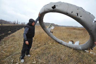
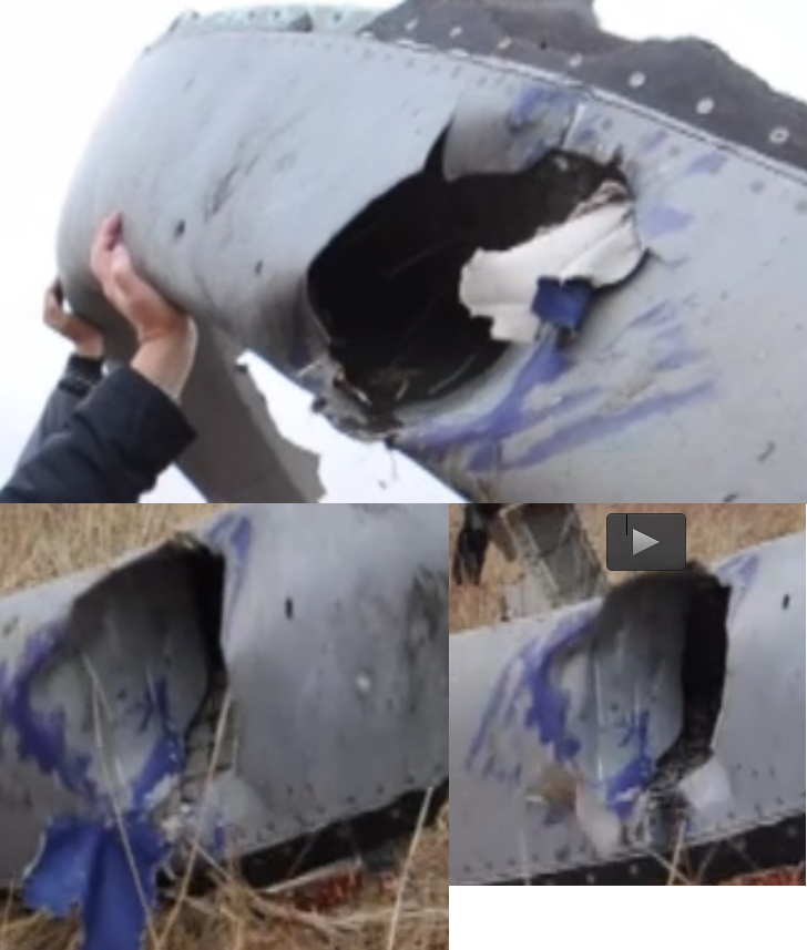
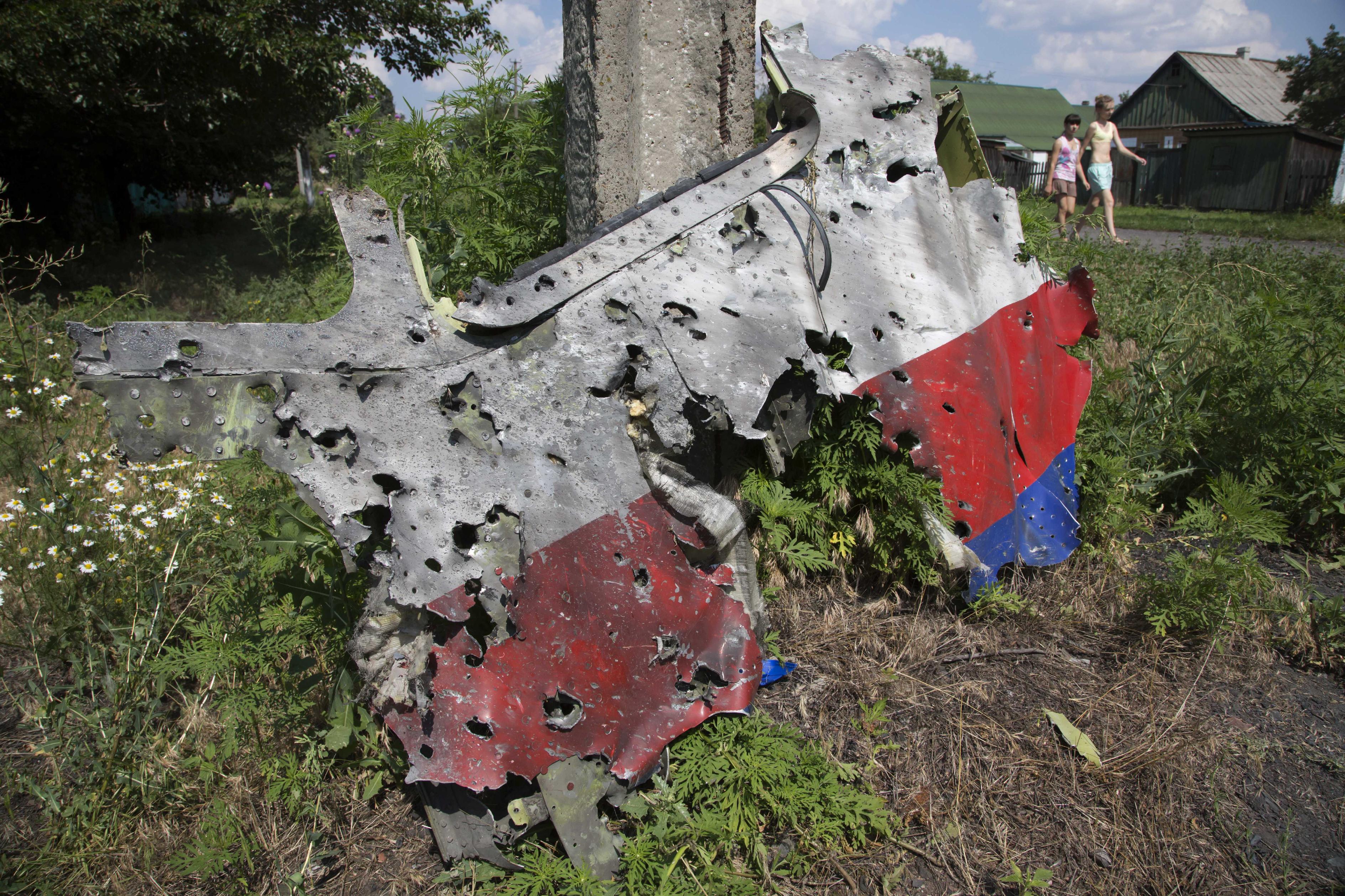
Very good shot of engine part with hole from collision. Or from splinters of Z missile, which have blue paint?
e70173b98eeed2ea2d31f33396663696.jpg
 
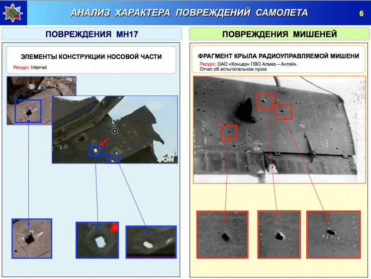
Shots of square holes due to buk fragment damage
b1f53d11c2e86c7f003b762ec17b4c84.jpg


Shot of same square holes in left engine cowling.
7418fc04211f0c07bc7cc579e59fca9f.jpg


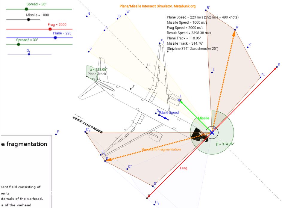
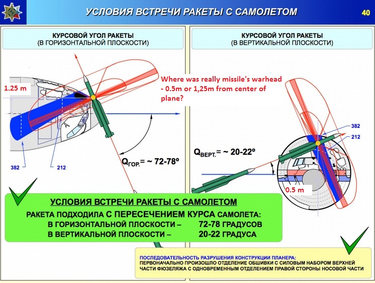
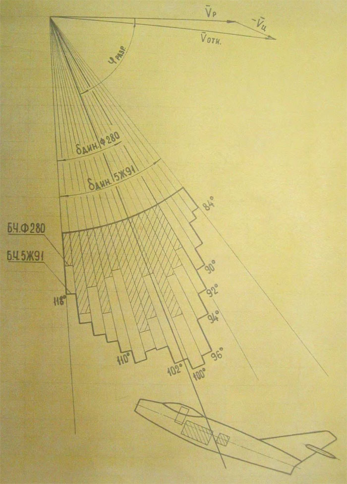
Diagram of expected fragment damage area from Snizhne launch. No square fragment damage expected to left engine.
a8a383881e99e20940ec51f7fe81463f.jpg


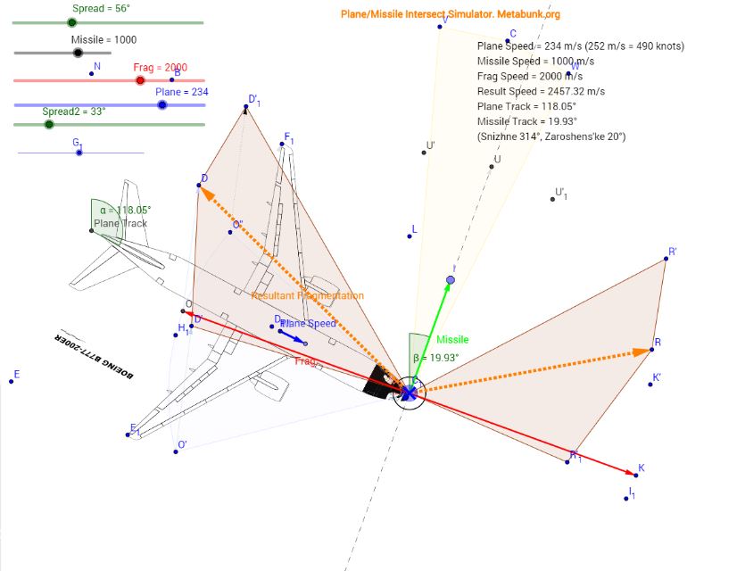
Diagram of expected damage from Zaroshens'kye launch. Square damage to left wing including engine predicted.
13fb73c578fdce0e32b04038ea3f7b16.jpg


Conclusion. Snizhne debunked. Zaroshens'kye quite likely
 
Last edited:
Shots of square holes due to buk fragment damage
b1f53d11c2e86c7f003b762ec17b4c84.jpg


Shot of same square holes in left engine cowling.
7418fc04211f0c07bc7cc579e59fca9f.jpg


Diagram of expected fragment damage area from Snizhne launch. No square fragment damage expected to left engine.
a8a383881e99e20940ec51f7fe81463f.jpg


Diagram of expected damage from Zaroshens'kye launch. Square damage to left wing including engine predicted.
13fb73c578fdce0e32b04038ea3f7b16.jpg


Conclusion. Snizhne debunked. Zaroshens'kye quite likely
Im trying to understand why S debunked? Can you help me?
1. Picture from AA compare damage from Buk missile with damage from soviet-era Buk missile. It looks like same. How it debunk certain launch location?
BTW this hole in co-pilot chair not from splinters.
fb258deada0e3aa4770f2e640904f178.jpg

Also im glad to see hole in floor which im found and marked now used by AA for debunk my version, lol.

2. Im wonder what size of holes in engine ring? It can help with identify splinters or not leave it. Im see hole with blue paint and hole on second photo (man raising ring) have size of human hand. Abit high for 9N314 pellets, no?
3. Simulation from Mick West describe angles for horisontal projection and for zero height plane/missile, also dont give info how angles changed with elevation angle of missile. Use it for debunk S missile or Z is not fair.
So im wanna see clear facts, not fantasy stories.
 
  • Agree
Reactions: Rob
And special painting "Freedon of Space" leave engine ring without blue paint.
Hole on 9-12 hours dont have blue paint despite on same damage here.
So selective Occam razor.
So you propose the area of blue paint on that convex area was caused by a blue fragment sliding smoothly along that convex area passing its paint to the inlet? It seems much more plausible that at some point during the painting process this part received blue paint.
 
Very good shot of engine part with hole from collision. Or from splinters of Z missile, which have blue paint?
e70173b98eeed2ea2d31f33396663696.jpg

That's not a good shot of the holes unless you mean the giant opening instead. At this stage it's very hard to understand what you're trying to claim exactly since the left engine would have surely taken some fragments in case of "Z" (see Wiley's post above). Blue paint? Might indicate a collision with a colored part of the plane. At least it could explain the size of that hole! Breaking up mid-air and crashing onto the ground will leave its marks.
 
So you propose the area of blue paint on that convex area was caused by a blue fragment sliding smoothly along that convex area passing its paint to the inlet? It seems much more plausible that at some point during the painting process this part received blue paint.
Ok, now story is
In Sep 2005 workers painting plane with blue paint and leave future hole without blue paint on one half. Time machine or witchcraft?
 
That's not a good shot of the holes unless you mean the giant opening instead. At this stage it's very hard to understand what you're trying to claim exactly since the left engine would have surely taken some fragments in case of "Z" (see Willey's post above). Blue paint? Might indicate a collision with a colored part of the plane. At least it could explain the size of that hole! Breaking up mid-air and crashing onto the ground will leave its marks.
So this hole from collision. How about other holes? Can they had source from collision too if we already found one from it?
 
  • Like
Reactions: Rob
Im trying to understand why S debunked? Can you help me?
1. Picture from AA compare damage from Buk missile with damage from soviet-era Buk missile. It looks like same. How it debunk certain launch location?

If you change the data you'll get different results, in this case you can indeed maintain "S". But you have to make the case why your suggested fragment cone should be used instead. Do we really have to choose between potential industrial propaganda and some outdated random drawing of a way older SAM?

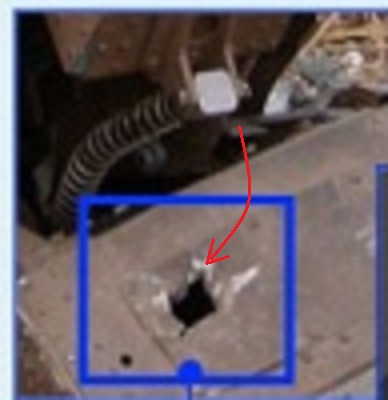
BTW this hole in co-pilot chair not from splinters.
fb258deada0e3aa4770f2e640904f178.jpg
Can you exclude it coming from the missile warhead using Z approach? Statistically it's only a few degree from the main kill zone and strays could be expected in that zone more than any other random angle. And could you point to definite proof this is co-pilot seat?

3. Simulation from Mick West describe angles for horisontal projection and for zero height plane/missile, also dont give info how angles changed with elevation angle of missile. Use it for debunk S missile or Z is not fair.
I agree here with you, perhaps for the first time! A more full 3D model would be needed for that and more 3rd party certainty on fragment cloud shape. But still, there are indications already even with the limited models, don't you think?
 
So this hole from collision. How about other holes? Can they had source from collision too if we already found one from it?

They look rather square and fragment size to me! But a close-up look might be needed and I don't consider it a fact yet either, if that's what you mean. What's visible so far is very indicative though.
 
About hole in engine ring with blue paint. Im look on video and found blue piece which catched by hole edge.
4b5c1f98ba1a2400e6518e29fbf80587.png

It very flexible and it is source of blue paint. Section of engine ring material dont have this flexible material in own structure so this material from outside source. Im think it part of left skin near cabine which detached by strike elements and decomrpession. It collided on high speed with engine part and weak fragment was catched.
Probability of this scenario can describe how engine can receive holes from own plane details which situated on plane axis before engines.
That's around 5:28 in the video. Looks more like a piece of fabric. It doesn't look like it could punch that hole into the inlet and then remain attached during a descent of 10000m. The inlet is made of composite, so it may by some kevlar reinforcement?
http://www.boeing.com/assets/pdf/commercial/airports/arff/arff777.pdf - page 10
 
If you change the data you'll get different results, in this case you can indeed maintain "S". But you have to make the case why your suggested fragment cone should be used instead. Do we really have to choose between potential industrial propaganda and some outdated random drawing of a way older SAM?


Can you exclude it coming from the missile warhead using Z approach? Statistically it's only a few degree from the main kill zone and strays could be expected in that zone more than any other random angle. And could you point to definite proof this is co-pilot seat?


I agree here with you, perhaps for the first time! A more full 3D model would be needed for that and more 3rd party certainty on fragment cloud shape. But still, there are indications already even with the limited models, don't you think?
1. Im dont choose between. Im choose facts which can be described by knowledge.
I will be glad if Z missile is possible, it very very good for me, personally.
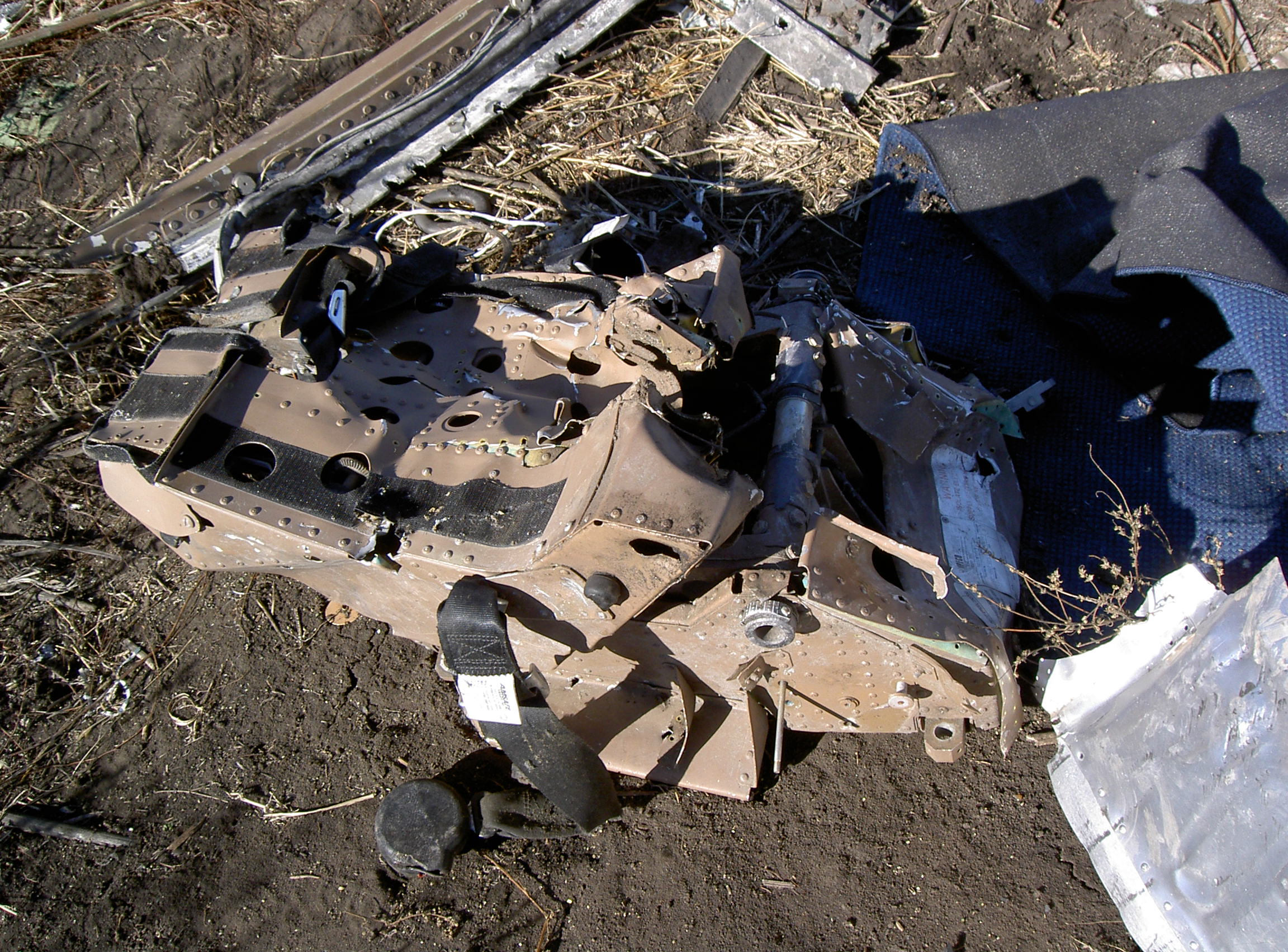
2. Im just show hole in co-pilot chair box is not hole from splinters. It hole from crushed down chair. This is co-pilot chair, pilot chair have squashed box.
8eb9caf1b8539b5ae40a69ffeb9eefe7.jpg

3. Mick's simulation good for debunk wrong info from AA about dynamic field of strike elements. But Z missile (and IMHO S missile) have elevation angle and height plane/missile so this tool dont show clear how missile damage a plane. Need find colission of fuselage and expanding ring for understand what projection should be use for calculate possible penetration angles.
 
What are the holes in the most famous piece of wreckage of MH17? Are these entry or exit holes? Or both?
ed9cc4a7e1f80cff37fec89e8f1b2308.jpg

entry holes,pic off same damage rear side shows what appears to be entry and mushrooming on support beam directly opposite,notice also lack off evidence off exit holes
646491_d0c059a774337c0c0cafcb9f5ef2a31bmar.jpg
 
So you propose the area of blue paint on that convex area was caused by a blue fragment sliding smoothly along that convex area passing its paint to the inlet? It seems much more plausible that at some point during the painting process this part received blue paint.
I do not think this is paint of a previous paint job. My guess a part of the forward fuselage was blown off, and touched the engine ring. Maybe that was the reason the engine ring dropped off the engine.
 
Last edited:
What are the holes in the most famous piece of wreckage of MH17? Are these entry or exit holes? Or both?
ed9cc4a7e1f80cff37fec89e8f1b2308.jpg
Hard to say to be honest. Remember the hull of the plane was pressurized so any thing puncturing it would release the pressure outwards, so entry holes could well look like exit holes as the air released forced its way out the hole the shrapnel came in folding the edges of those holes outwards. (You can repeat this with a simple experiment, take a can of beer or soda, shake it up to maximize the pressure inside and shoot it with a .177 air gun, you will see that as often or not the edges of the entrance hole are forced outwards by the escaping pressure.)

What is more as this will result in fractures along lines of least resistance in the aircraft skin, the cracks and tears will not necessarily run along the same lines as each other.
 
Last edited:
It does not think this is paint of a previous paint job. My guess a part of the forward fuselage was blown of, and touched the engine ring. Mayne that was the reason the engine ring dropped of the engine.
Agree, it probably wasn't a previous paint job. Yet, because the area with blue paint is convex, IMHO the paint can only have been transferred by something "brush-like", if it had been a solid object that carried the paint the area now should be concave (because the solid object would have left the area of contact in such a shape). That blue piece of fabric - whatever it is - could be the "brush-like" thing that transferred the paint. It can't be the object that punched the hole.

BTW, whatever punched the hole hadn't enough energy to penetrate the structure behind it.

P.S: One possibility could be, the blue fabric is a part of the business class carpet that was sucked towards the engine during breakup:
55257533a73ec039e3ec235c01011378._.jpg

http://www.seatguru.com/airlines/Malaysia_Airlines/Malaysia_Airlines_Boeing_777-200.php
 
Last edited:
The piece of whatever materiaal seems to be a bit too light for being carpet. It could be some materiaal like to wrap something up. Maybe something from the forward cargo belly. I guess the paint of that material was partially washed away by rain and made those blue staines.
I doubt it is from debris.
 
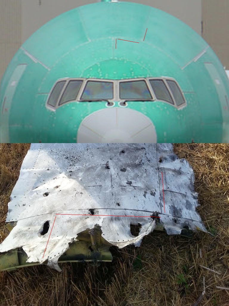
This is another interesting piece of debris. It is often not displayed in various pictures showing an overview of debris. It is also not to be seen in the DSB reconstruction.

The piece is located directly behind the cockpit on the lefthand side. Hardly any entry holes from the outside (which should be for a Snizhne launch) but many holes in the longitude axis of the aircraft (expected for a Z. launch)
<edit> A few posts later user Ole attended me that this piece is not located behind the cockpit.


sta2365-overview.jpg

MLA55cb23_stropkokpitu_DCA.jpg
9d54a1c53867c99b65766969e029c113.png
 
Last edited:
MH17_STA_287-298.jpg
View attachment 13694
This is another interesting piece of debris. It is often not displayed in various pictures showing an overview of debris. It is also not to be seen in the DSB reconstruction.

The piece is located directly behind the cockpit on the lefthand side. Hardly any entry holes from the outside (which should be for a Snizhne launch) but many holes in the longitude axis of the aircraft (expected for a Z. launch)
This piece is even futher back and shows many entry holes
 
Last edited:
This is another interesting piece of debris. It is often not displayed in various pictures showing an overview of debris. It is also not to be seen in the DSB reconstruction.

The piece is located directly behind the cockpit on the lefthand side. Hardly any entry holes from the outside (which should be for a Snizhne launch) but many holes in the longitude axis of the aircraft (expected for a Z. launch)

View attachment 13691
View attachment 13692 View attachment 13693
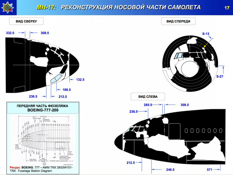
I'm pretty sure AA has this piece wrong. There is only one single piece from >STA 236.5 and it's always the same, photographed a million times. The three holes between STA 236.5 and STA 240 (red circles in your first photo) are very characteristic. That piece must be located here:
06c8160c5bf189eec87822a8705c930c.jpg

More here: http://www.nytimes.com/interactive/...rs-clues-on-why-flight-17-went-down.html?_r=0
This is a slide that somebody corrected accordingly:
a794507f92f5d399a16b4c981996c8b1.jpg
 
I'm pretty sure AA has this piece wrong. There is only one single piece from >STA 236.5 and it's always the same, photographed a million times. The three holes between STA 236.5 and STA 240 (red circles in your first photo) are very characteristic.
You are right. This is the same piece! Thanks for pointing out.
 
Strange entry holes on part which must have exit holes by AA position of missile.
I don't understand why there should be a difference between entry and exit holes between the S and the Z scenario. The spot where the detonation took place is quite clear, I don't think the place where AA put it can be contested by much more than ~1m back or forth. The difference between S and Z then cannot be the direction of the trajectories. The difference only can be the direction of the main damage and additionally there might be directions in which no impacts should occur and other directions which shouldn't be spared.

The impacts in the copilots seat may give rise to doubt about the Z scenario, because that's a direction that maybe should have been spared by a Z-missile.
OTOH for the S scenario one would expect the main damage to be in the direction of the copilots seat, one wouldn't expect the starboard side of the cockpit spared and one wouldn't expect the main damage in the cockpit floor to the left of the captains seat.
All that under the caveat that the most reliable information on the fragment distribution we have is the imprecise information from AA.

But it doesn't change the fact, that once the location of the detonation is defined, the directions of the impact will be the same for Z and S, the only think that could distinguish the two scenarios is the distribution of the impacts.
 
I'm pretty sure AA has this piece wrong. There is only one single piece from >STA 236.5 and it's always the same, photographed a million times.

You might be right but then again that piece was specifically mentioned and placed as cockpit roof element also in the Dutch Safety Board's preliminary report like in the image below. And I think I remember AA said on the press conference they used those findings as basis. The Safety Board also mentioned all those components were not recovered yet for forensics at the time of writing. It's therefore quite possible the pieces were not placed properly during the first review.

onderzoeksraad_prem_fig7.png
 
I don't understand why there should be a difference between entry and exit holes between the S and the Z scenario.
Because you dont understand how damage from both location changed in 3D. It why you trust in damage shown by AA.
The spot where the detonation took place is quite clear, I don't think the place where AA put it can be contested by much more than ~1m back or forth.
But AA dont show certain place of detonation, their picture have manipulation with position of missile in vertical and horisontal projection - little trick for falsify results.
The difference between S and Z then cannot be the direction of the trajectories. The difference only can be the direction of the main damage and additionally there might be directions in which no impacts should occur and other directions which shouldn't be spared.
Differences between Z and S is direction of trajectories. Do you think cone cut cylinder/cone equally from any direction?
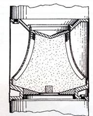
Im dont see main damage on MH17. Where is it? How non-directed warhead can have main damage? By lancet? Barrel-like warheads dont have it. Barrel shape is specific type of warhead which used for wide disclosure angles. Differences between cylinder and barrel shape of warheads in wide disclosure angles. Cylinder typically have disclosure angle near 20 degree, when barrel have 30-60 degree or more (depend from fatness). If you want strike target with concentrated damage (at least dont flying to sides) - you should use cylinder warhead, and if you need even more concentration - you use specific shape of surface like it
42082b61217492c9fe7542f6c4124269.jpg

or two detonators on opposite sides. Warhead 9N314 is fat barrel-like with only one primer.
AA give enough info for understand how looks static field of strike elements in really. They show:
1. angles of different fractions
2. speed of fragments
It give data for calculate dynamic field of strike elements.
But AA give a false info about lancet and angles of dynamic field of strike elements. Just for manipulate with damage pattern on plane. Same trick used with missile position. And im dont talk even about aiming point of missile.
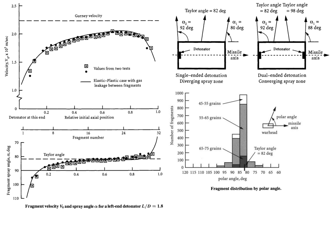
For example, let see what deviation from perpendicular have 9N314M warhead? They show angles 68-112 (for inner layer of heavy fragments, median angle is 90 degree) and 72-124 degree (for outer layer of light elements, median angle is 98 degree) - it is absolutely right info which have confirmation from theory and experiments.
Important: Warhead 9N314 with top-placed primer have 0 degree deviation from perpendicular for heavy pellets and 8 degree deviation for light pellets!
Now we look on cylinder-like warhead with theory and experiments results. Primer aslo placed on top. We look on deviation angle and it is ... 8 degree too!
3fad3d229529d607c27ec7b2e36a1939.png

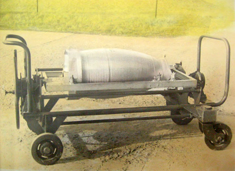
Another proof for working of that theory in real weapon is old-soviet warhead 5Zh51.
226ac2380580a0c2735b9c6e64af8670.jpg

Have barrel shape (fatness lesser then 9N314 warhead) with inclination of surface and top end primer. Both tricks (inclination fo surface and edge point of detonator) give disclosure angles 84-118 degree (12 degree deviation, wide 34 degree).
3a0568524ecf15a8add9f4af733123c0.jpg

But dynamic field of strike elements rotate angles to 52-87 degree (forward rotation is near 32 degree from static angles).
Zero degree deviation for heavy pellets have reason. They situated in inner layer and first should transmitt their energy to outer layer which dont have barrier and leave warhead high-pressure zone precisely as theory describe it - with 8 degree deviation. But heavy pellets have little delay in gaining speed (lose energy by exchange with light pellets and have more weight so need more energy for same acceleration) so during this delay explosive in opposite end already exploding and affect on disclosure angles of heavy pellets too. It why heavy pellets dont have deviation of median angles. Also barrel-like shape affect more on angles of most strike elements (disclosure angles wide 55-56 degree instead of cylindrical 20 degree).
After that theory we can just add missile speed to fragments speed and receive real dynamic field of strike elements - it dont have lancet and turning it much more to forward then AA want it.
So how AA receive lancet on 90 degree? Magic? They need it for show damage pattern close to real, it all.
The impacts in the copilots seat may give rise to doubt about the Z scenario, because that's a direction that maybe should have been spared by a Z-missile.
OTOH for the S scenario one would expect the main damage to be in the direction of the copilots seat, one wouldn't expect the starboard side of the cockpit spared and one wouldn't expect the main damage in the cockpit floor to the left of the captains seat.
All that under the caveat that the most reliable information on the fragment distribution we have is the imprecise information from AA.
Im trying to build 3D-model for describe possible damages.
But it doesn't change the fact, that once the location of the detonation is defined, the directions of the impact will be the same for Z and S, the only think that could distinguish the two scenarios is the distribution of the impacts.
This is absolutely not true. Angle between course of Z missile and S missile near 60 degree. How it possible to have same distribution for both? In really, without AA magic points of detonation with perpendicular saw.

 
Last edited:
or two detonators on opposite sides. Warhead 9N314 is fat barrel-like with only one primer.
AA give enough info for understand how looks static field of strike elements in really. They show:
1. angles of different fractions
2. speed of fragments
It give data for calculate dynamic field of strike elements.
But AA give a false info about lancet and angles of dynamic field of strike elements. Just for manipulate with damage pattern on plane. Same trick used with missile position. And im dont talk even about aiming point of missile.
For example, let see what deviation from perpendicular have 9N314M warhead? They show angles 68-112 (for inner layer of heavy fragments, median angle is 90 degree) and 72-124 degree (for outer layer of light elements, median angle is 98 degree) - it is absolutely right info which have confirmation from theory and experiments.
Important: Warhead 9N314 with top-placed primer have 0 degree deviation from perpendicular for heavy pellets and 8 degree deviation for light pellets!
Now we look on cylinder-like warhead with theory and experiments results. Primer aslo placed on top. We look on deviation angle and it is ... 8 degree too!
3fad3d229529d607c27ec7b2e36a1939.png
Fitting the 2D flight path of the missile into that information together with the trajectories identified so far, I get something like this:

For the lighter fragments:
light.jpg


For the heavier fragments:
heavy.jpg

The missile itself would go this way (in the frame of reference of the aircraft):
missile.jpg

Decelerated parts of the missile would point some more into the direction of the wing.


And this is what makes the "pure" Snizhne scenario unlikely.
S.jpg


PS: My modified project, that allows to tweak the direction of the frag sector, is here:
https://tube.geogebra.org/m/YaP2MqdF
It's a bit cumbersome because the frag vector doesn't turn when turning the missile vector.
 
Last edited:
How non-directed warhead can have main damage? By lancet? Barrel-like warheads dont have it. Barrel shape is specific type of warhead which used for wide disclosure angles.

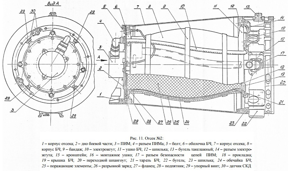
Just calling the 9N314M warhead barrel shape might be a bit simplifying. It appears to have some distinct features:
warhead.jpg


Probably the shape of the back half of the warhead is not the result of chance but of design. Taking your graphs above, (depicting the non-trivial angular distribution and the angular velocity distribution), taking into account the shape of the warhead, and taking into account the unknown arrangement of heavy and light fragments in the warhead, I find it premature to conclude a lancet containing 42 percent of the fragment mass and 50 percent of the kinetic energy can not exist. I tend to give the AA Engineers the credit to have put lots of experience and lots of brainpower into the design of their warheads. If they released bunk data to the JIT, it will be noticed.
 
According to the diagrams in #482 above, this area would be hit from a Zaroshens'kye launch but would not be hit by a Snizhne launch.
A pattern is emerging
according to A-A diagram these should be exit holes not entry for Z launch,well forward of missiles burst point in which even they say frags are sweeping forward
 
Just calling the 9N314M warhead barrel shape might be a bit simplifying. It appears to have some distinct features:
Warhead 9N314M have barell-like shape.
Probably the shape of the back half of the warhead is not the result of chance but of design.
All sides equal to opposite sides and have gibbose medium part (which affect on wide disclosure angles - 56 degree).
6dba594cd9a5ea9334533324ee5d66c1.jpg

Taking your graphs above, (depicting the non-trivial angular distribution and the angular velocity distribution), taking into account the shape of the warhead, and taking into account the unknown arrangement of heavy and light fragments in the warhead
AA give basic info what angles and speed have fragments. Im show how it supported by theory and practice. Do you have questions about Gurney equation and Taylor angle?
I find it premature to conclude a lancet containing 42 percent of the fragment mass and 50 percent of the kinetic energy can not exist. I tend to give the AA Engineers the credit to have put lots of experience and lots of brainpower into the design of their warheads. If they released bunk data to the JIT, it will be noticed.
Ok. Step by step:
1. Shape of warhead
fat barrel
disclosure angles
theory = 30-60 (depend from fatness)
9N314 by AA info = 56 degree
2. Detonator position
top end of warhead
affect on disclosure angles
theory = move back by 8 degree
9N314 - move back by 8 degree for outer layer, dont affect for inner layer.
3. Speed of pellets
theory (Gurney equation for cylinder warhead) = 1100-2000 m/s
9N314 by AA info = 1400-2400 ms (abit higher from explosive type and barrel shape)
So we see how AA info about static field of strike elements fully supported by theory. So why you cancel theory for next step called dynamic field of strike elements? What reason? Anothe physic law? Chemistry? Math? Unique for soviet science and engineering?
Answer is simple - despite on science, AA trying to show wrong info about dynamic field of strike elements.
They hope people believe to their manipulated data because most people never heard about theory and dont know experiments data. But trust to developer and manufacturer. Sorry, but im dont trust - they create this weapon, yes. They keep in secret technical data - it law in Russia. They keep silence during year, till bellingcat debunk russian DoD false satellite photos and DSB send draft of final report. They have magical lancet when other barrels dont have. They have perpendicular saw which all moving warheads have rotated to forward.
So believe or know? Hard to choose. Not for me.
Ans yes JIT will be noticed. Place this false data on same place with russian DoD briefing, photo of ukrainian fighter shot down MH17 etc.
But here we can debunk lie with open sources and Earth science, without believe in myth.
P.S. BTW 2 facts:
1. During development 9N314 have killing range up to 25m but when start firing tests found too low density of strike elements on target surface. So engineers just lowering killing range to 17 m (distance of initiation for radio fuse) for receive enough results. It how correct their math was - need decrease range for enough density.
2. Soviet Union dont have good radiology.
 
Last edited:
Fitting the 2D flight path of the missile into that information together with the trajectories identified so far, I get something like this:


And this is what makes the "pure" Snizhne scenario unlikely.
View attachment 13704
So you looking on horisontal projection of plane, missile and pellets. Well! But what happen in vertical projection?
 
Do you have questions about Gurney equation and Taylor angle?
Not really. But the graphics you posted seem to leave the designers some degree of freedom by the way they arrange heavy an light fragments, and by the way they shape the actual surface of the warhead.

My models from post #515 take your numbers at face value and still run into serious problems with the Snizhne scenario. If one wants to talk away these problems with some 3D inclination of the missile at the intercept point, then the missile must have been launched much closer to the last FDR position thus no longer being a Snizhne-missile but becoming a Torez-missile.

Taking into account AA has the roof debris located wrong, a missile in a diving inclination would make more sense, moving the expected damage to the roof of the a/c further to the port side and moving the expected damage below the point of detonation further to the starboard side. Thus the impacts on the copilot's seat would be even easier to explain. So taking your numbers at face value IMHO the least unlikely scenario is a long range shot from somewhere close to 180°.

Another data point that has to be taken into account is the fact that the fuel didn't ignite until the a/c hit the ground, so it's unlikely that a large amount of shrapnel or the missile itself hit the tanks.
 
Back
Top