I don't understand why there should be a difference between entry and exit holes between the S and the Z scenario.
Because you dont understand how damage from both location changed in 3D. It why you trust in damage shown by AA.
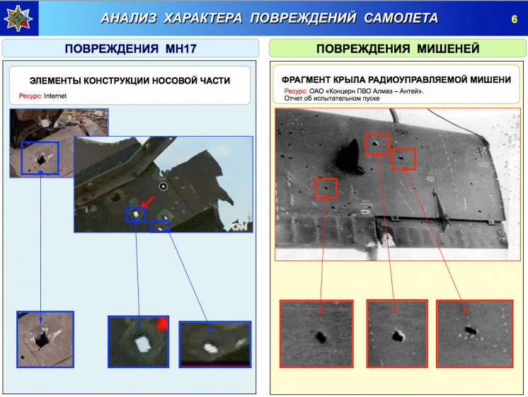
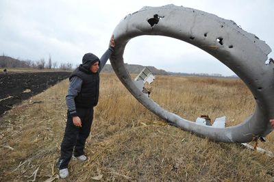
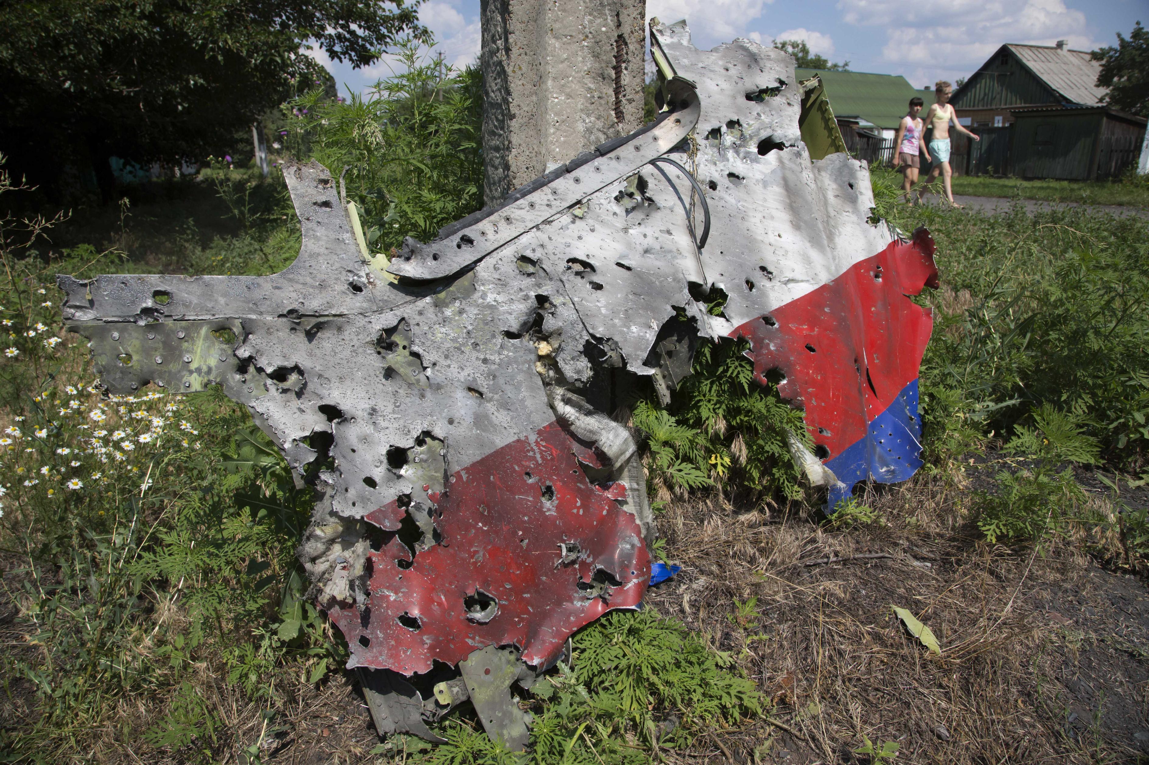
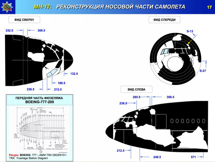
The spot where the detonation took place is quite clear, I don't think the place where AA put it can be contested by much more than ~1m back or forth.
But AA dont show certain place of detonation, their picture have manipulation with position of missile in vertical and horisontal projection - little trick for falsify results.
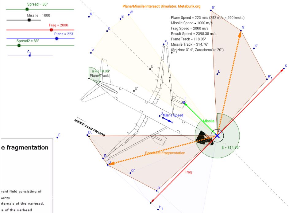
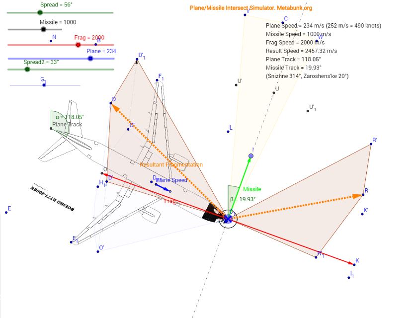
The difference between S and Z then cannot be the direction of the trajectories. The difference only can be the direction of the main damage and additionally there might be directions in which no impacts should occur and other directions which shouldn't be spared.
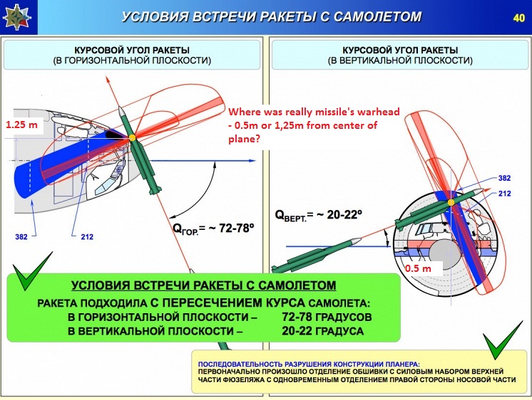
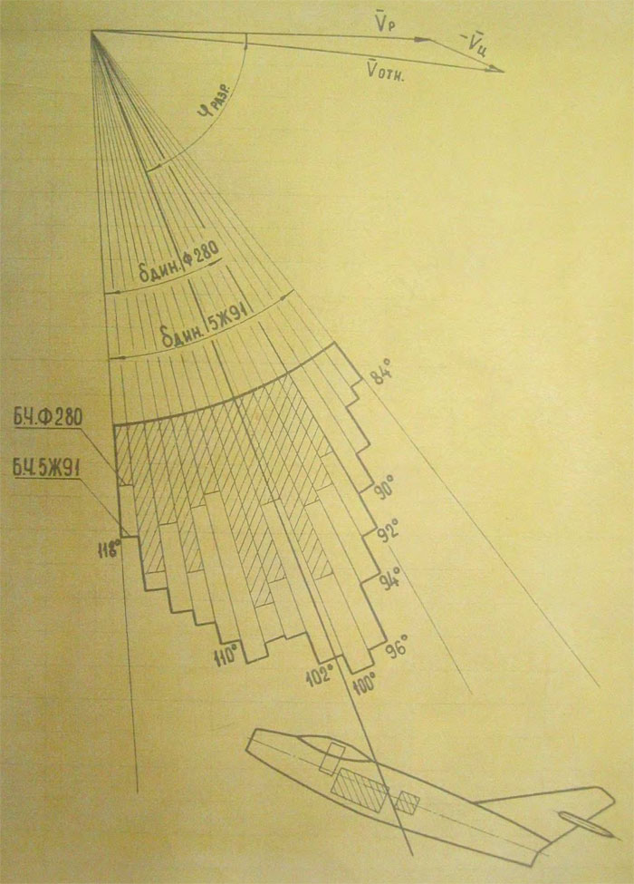
Differences between Z and S is direction of trajectories. Do you think cone cut cylinder/cone equally from any direction?
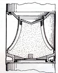
Im dont see main damage on MH17. Where is it? How non-directed warhead can have main damage? By lancet? Barrel-like warheads dont have it. Barrel shape is specific type of warhead which used for wide disclosure angles. Differences between cylinder and barrel shape of warheads in wide disclosure angles. Cylinder typically have disclosure angle near 20 degree, when barrel have 30-60 degree or more (depend from fatness). If you want strike target with concentrated damage (at least dont flying to sides) - you should use cylinder warhead, and if you need even more concentration - you use specific shape of surface like it
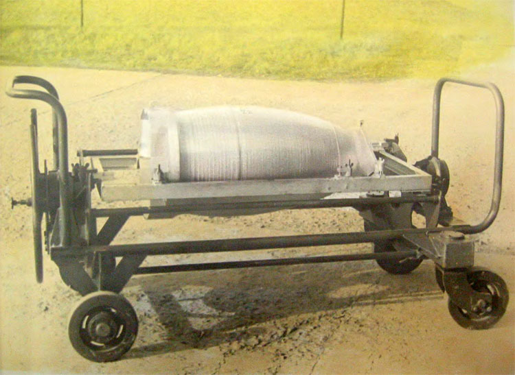
or two detonators on opposite sides. Warhead 9N314 is fat barrel-like with only one primer.
AA give enough info for understand how looks static field of strike elements in really. They show:
1. angles of different fractions
2. speed of fragments
It give data for calculate dynamic field of strike elements.
But AA give a false info about lancet and angles of dynamic field of strike elements. Just for manipulate with damage pattern on plane. Same trick used with missile position. And im dont talk even about aiming point of missile.
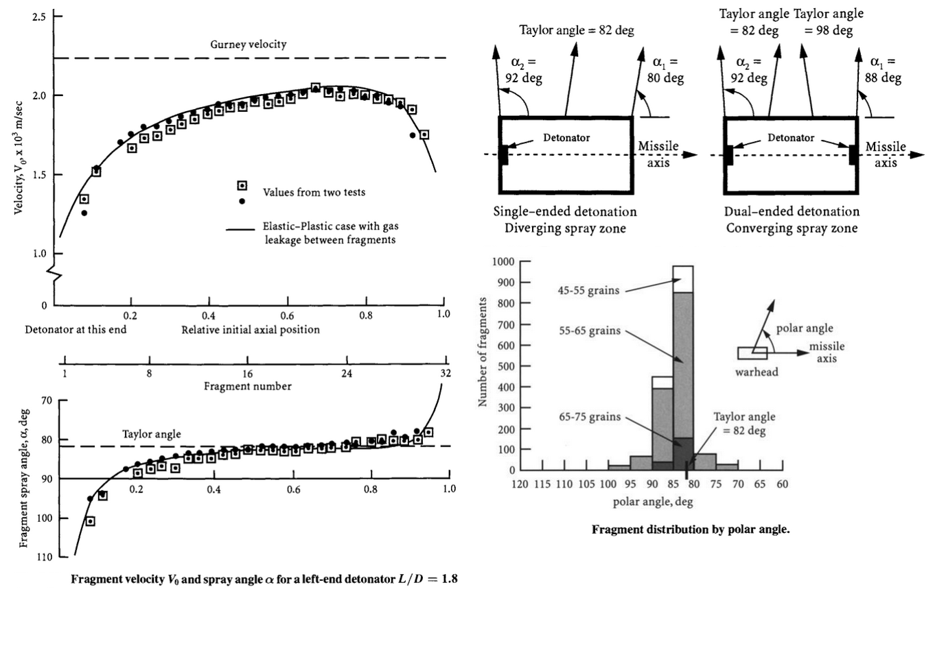
For example, let see what deviation from perpendicular have 9N314M warhead? They show angles 68-112 (for inner layer of heavy fragments, median angle is 90 degree) and 72-124 degree (for outer layer of light elements, median angle is 98 degree) - it is absolutely right info which have confirmation from theory and experiments.
Important: Warhead 9N314 with top-placed primer have
0 degree deviation from perpendicular for heavy pellets
and 8 degree deviation for light pellets!
Now we look on cylinder-like warhead with theory and experiments results. Primer aslo placed on top. We look on deviation angle and it is ...
8 degree too!
Another proof for working of that theory in real weapon is old-soviet warhead 5Zh51.
Have barrel shape (fatness lesser then 9N314 warhead) with inclination of surface and top end primer. Both tricks (inclination fo surface and edge point of detonator) give disclosure angles 84-118 degree (12 degree deviation, wide 34 degree).
But dynamic field of strike elements rotate angles to 52-87 degree (forward rotation is near 32 degree from static angles).
Zero degree deviation for heavy pellets have reason. They situated in inner layer and first should transmitt their energy to outer layer which dont have barrier and leave warhead high-pressure zone precisely as theory describe it - with 8 degree deviation. But heavy pellets have little delay in gaining speed (lose energy by exchange with light pellets and have more weight so need more energy for same acceleration) so during this delay explosive in opposite end already exploding and affect on disclosure angles of heavy pellets too. It why heavy pellets dont have deviation of median angles. Also barrel-like shape affect more on angles of most strike elements (disclosure angles wide 55-56 degree instead of cylindrical 20 degree).
After that theory we can just add missile speed to fragments speed and receive real dynamic field of strike elements - it dont have lancet and turning it much more to forward then AA want it.
So how AA receive lancet on 90 degree? Magic? They need it for show damage pattern close to real, it all.
The impacts in the copilots seat may give rise to doubt about the Z scenario, because that's a direction that maybe should have been spared by a Z-missile.
OTOH for the S scenario one would expect the main damage to be in the direction of the copilots seat, one wouldn't expect the starboard side of the cockpit spared and one wouldn't expect the main damage in the cockpit floor to the left of the captains seat.
All that under the caveat that the most reliable information on the fragment distribution we have is the imprecise information from AA.
Im trying to build 3D-model for describe possible damages.
But it doesn't change the fact, that once the location of the detonation is defined, the directions of the impact will be the same for Z and S, the only think that could distinguish the two scenarios is the distribution of the impacts.
This is absolutely not true. Angle between course of Z missile and S missile near 60 degree. How it possible to have same distribution for both? In really, without AA magic points of detonation with perpendicular saw.