Debunked: Celtic Cross on Mars [Impression from Screw Head on X-Ray Spectrometer]

Mick West

Administrator
Staff member

Source: http://mars.jpl.nasa.gov/mer/gallery/all/opportunity_m3720_text.html

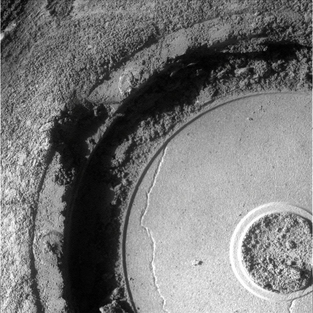
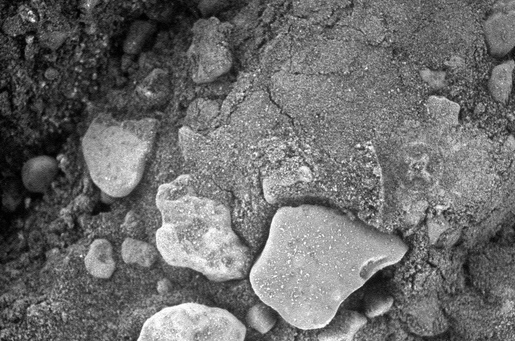
This image of a cross in a circle on the surface of Mars is real. It's from the Opportunity rover, Sol 3720. It's from the Microscopic Imager camera, so it's quite small.

The most obvious clue is that it look like it's in soft sand. You can see cracks in the crumbling sand to the left of the cross, and there's a curve right next to it, that looks like something was pressed into the sand. So the obvious candidate for the source of the cross is the rover itself.

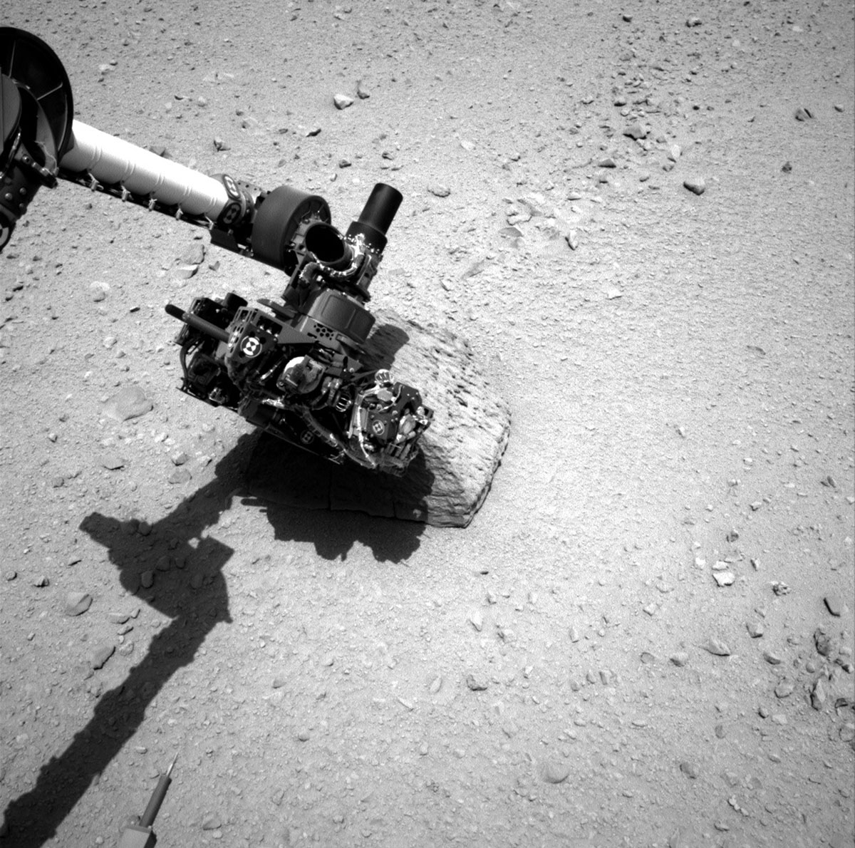
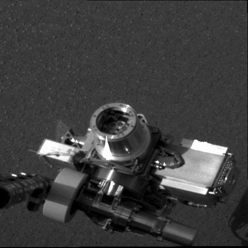
And it turns out there is a very simple explanation. The x-ray spectrometer, seen here as it currently is on Mars:


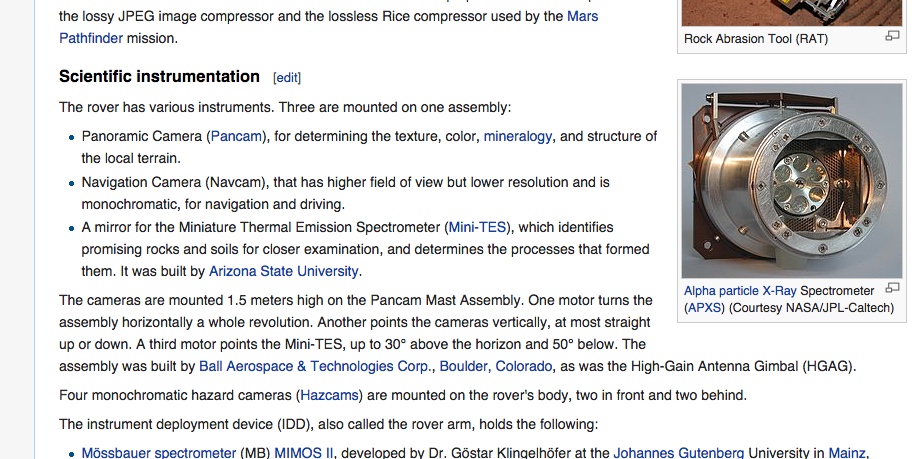
Here's a close up of a test version of the instrument.


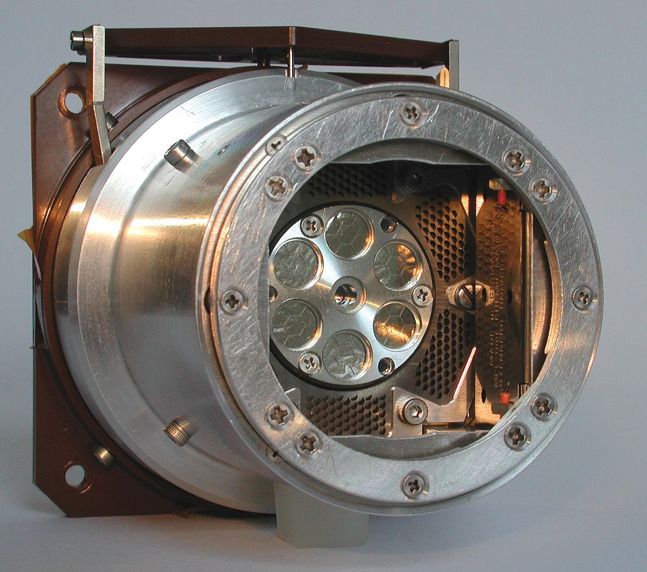
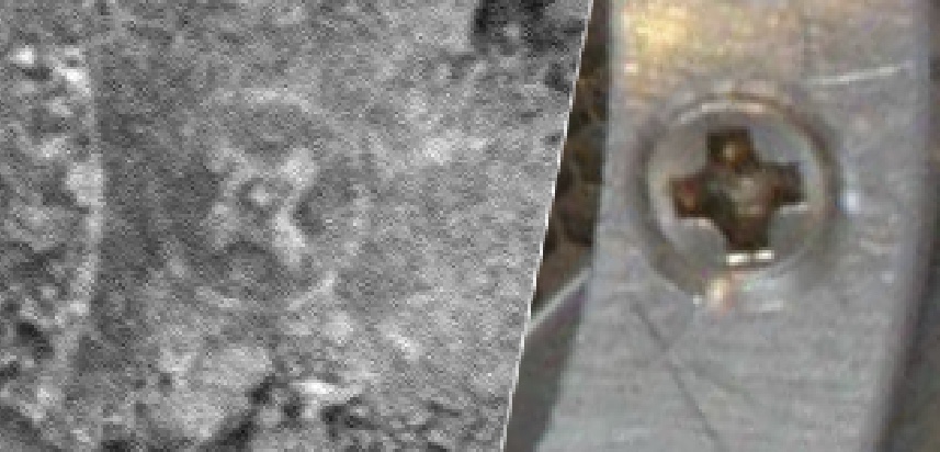
This is pressed against the rocks it is sampling to get the most accurate. Notice the screw heads are recessed. When this was pressed into the sand the cross came from the screw head, the circle came from the recess, and the curved line is from the inside curve of the instrument.


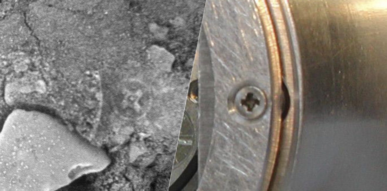
The screws are a variety of distances from the inner curve:


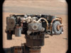
Here it is in action, pressed up against a rock:
 
Yes, there is now human presence on Mars. Heisenberg principle. That smiley face you will eventually see from an orbital imager might be rover tracks as an April Fools joke from a kid at JPL.

But.... Having lived in Ireland for a while, the Celts could very well have colonized Mars with little difficulty, as long as a few barrels of Guinness were available.
 
Last edited:
I though at first that the tracks might have screws in them, but they are perfectly smooth. Its quite obviously the spectrometer when you look at it. The amazing thing is that people will still believe it's something else.
 
You did not bother to check the NASA log page of the Opportunity rover. That log page shows that there was no use of the APXS in the period during which the Mars "Celtic Cross" photo was taken (July 9 to July 17th) -- a period during the rover was on the move -- until the night AFTER the photo was taken. The NASA log of Opportunity's activities refutes your hypothesis that the APXS was the cause of this "Celtic cross." See the blog post below for the details:

http://www.futureandcosmos.blogspot.com/2014/10/why-celtic-cross-on-mars-cannot-be.html

That's not a log. It's just a condensed description of events. It does not include everything that happened, just some events of interest. It does note that the the APSX was used on that day.

http://www.nasa.gov/mission_pages/mer/opportunity-update.html#.VEnez5PF__A
The rover has been busy with driving on six of the last eight days (sols) with some robotic work on one of the two non-driving sols. Opportunity moved a total of 797 feet (243 meters) over the eight-sol period, collecting targeted Panoramic Camera (Pancam) images before each drive and Navigation Camera (Navcam) panoramas after each drive. The vehicle did experience another Flash-induced reset event during the drive on Sol 3724 (July 15, 2014). Although these resets have occurred before, this was the first time that it happened during a drive. The flight team was able to restore normal operations with the rover on the very next sol. The project continues to investigate these Flash-related anomalies.

The one sol of in-situ (contact) science was the first sol of a two-sol autonomous 'touch 'n go' where the rover used the robotic arm (the 'touch') on Sol 3720 (July 11, 2014), to collect a Microscopic Imager mosaic of the surface target 'Trebia,' followed by an overnight contact integration measurement performed by the Alpha Particle X-ray Spectrometer (APXS). On the next sol (Sol 2721; July 12, 2014), the rover drove (the 'go') over 213 feet (65 meters) with mid-drive imaging. Opportunity will collect an atmospheric argon measurement with the APXS on the evening of Sol 3725 (July 17, 2014). The rover is in good health and operations are nominal.

As of Sol 3725 (July 17, 2014), the solar array energy production was 652 watt-hours with an atmospheric opacity (Tau) of 0.780 (Sol 3724; July 15, 2014) and a solar array dust factor of 0.854 (Sol 3724).
Content from External Source
 
Last edited:
I think this is the right screw head as if you look closely the lines DON'T exactly line up in the mars pic. or on the APXS screws. Pretty huge coincidence if this wasn't from a screw!


Re: Interesting microscopic(?) artefact in NASA Mars Photograph (Sol 3720)
Try a print of these (the screw head itself rather than the drive) in sand/plasticine/wax/putty and compare:

Torq-set


A set of torq-set bits

Torq-setis a cruciform screw drive used in torque-sensitive applications.[38]The Torq-set head is similar in appearance to a Phillips drive in that it has a cross with 4 arms. In Torq-set however, the lines are offset from each other, so they do not align to form intersecting slots across the top of the head. Because of this, a regular Phillips or flat-blade screwdriver will not fit the head.It is used in aerospace applications, e.g., theB-2stealth bomber.[38]Phillips Screw Company owns the name and produces the fasteners.

The applicable standards that govern the Torq-set geometry are National Aerospace Standard NASM 33781 and NASM 14191 for the ribbed version.The ribbed version is also known as ACR Torq-set.[39]
Content from External Source
http://projectavalon.net/forum4/sho...aph--Sol-3720-&p=888369&viewfull=1#post888369
 
Well it's obvious there is a semi-circular imprint to the left of the imprint in question. And besides, are the people of NASA impervious to human log error by a few hours? I'm sure it's happened once or twice ...
 
Yes, there is now human presence on Mars. Heisenberg principle. That smiley face you will eventually see from an orbital imager might be rover tracks as an April Fools joke from a kid at JPL.

But.... Having lived in Ireland for a while, the Celts could very well have colonized Mars with little difficulty, as long as a few barrels of Guinness were available.
Meh, Guinness is a relatively new thing. What we'd have needed was poteen.
 
Well it's obvious there is a semi-circular imprint to the left of the imprint in question. And besides, are the people of NASA impervious to human log error by a few hours? I'm sure it's happened once or twice ...

He is referring to the order of events listed below. I think it's more likely that it simply does not list every single little movement of the arm.

If they want to take a microscopic imaging mosaic in conjunction with and APSX scan, then it makes sense to first position the APSX agains the surface, and record that position for the camera. You then remove the APSX, position the camera to take photos using daylight, then reposition the APSX for the overnight scan.

The bolded text is simply cut and paste every time they do a Microscopic imager in conjunction with APSX.

That's not a log. It's just a condensed description of events. It does not include everything that happened, just some events of interest. It does note that the the APSX was used on that day.

http://www.nasa.gov/mission_pages/mer/opportunity-update.html#.VEnez5PF__A
The rover has been busy with driving on six of the last eight days (sols) with some robotic work on one of the two non-driving sols. Opportunity moved a total of 797 feet (243 meters) over the eight-sol period, collecting targeted Panoramic Camera (Pancam) images before each drive and Navigation Camera (Navcam) panoramas after each drive. The vehicle did experience another Flash-induced reset event during the drive on Sol 3724 (July 15, 2014). Although these resets have occurred before, this was the first time that it happened during a drive. The flight team was able to restore normal operations with the rover on the very next sol. The project continues to investigate these Flash-related anomalies.

The one sol of in-situ (contact) science was the first sol of a two-sol autonomous 'touch 'n go' where the rover used the robotic arm (the 'touch') on Sol 3720 (July 11, 2014), to collect a Microscopic Imager mosaic of the surface target 'Trebia,' followed by an overnight contact integration measurement performed by the Alpha Particle X-ray Spectrometer (APXS). On the next sol (Sol 2721; July 12, 2014), the rover drove (the 'go') over 213 feet (65 meters) with mid-drive imaging. Opportunity will collect an atmospheric argon measurement with the APXS on the evening of Sol 3725 (July 17, 2014). The rover is in good health and operations are nominal.

As of Sol 3725 (July 17, 2014), the solar array energy production was 652 watt-hours with an atmospheric opacity (Tau) of 0.780 (Sol 3724; July 15, 2014) and a solar array dust factor of 0.854 (Sol 3724).
Content from External Source
 
I'm sorry Mike but even you measure all the "various" screws on the spectrometer, the ratios from the chamfer for the screw head to the housing inside radial curve impression in the sand do not work. This is an artificial object on Mars.
 
I'm sorry Mike but even you measure all the "various" screws on the spectrometer, the ratios from the chamfer for the screw head to the housing inside radial curve impression in the sand do not work. This is an artificial object on Mars.

Please explain what "does not work", provide your diagrams, measurements, and math.
 
Sorry for coming back on this topic 3 years after, but kimc was right. Strange that nobody continued the discussion.
I fully agree on debunking, doing the same on many similar fake "proofs", but here, your explanation is wrong. I had the curiosity to measure the sizes; MOST of the ratios between APXS and the Mars picture don't match and this is not within "sand-print" errors, if far larger, like 2/1. I said most cause the only one acceptable would be the screw head/screw cut, to "insert" a reference, although this is also in contradiction with the fact the screw hole left no track and is outer.. Here are the measurements in pixels; you can attribute 1, even 2 pixels error (2 would be really exaggerated, visible, but let's assume it possible..):

APXS:
604 640 flange (ellipse, oblique view, same holds for all, does not affect ratios, diags corrected)
42.5 45 screw
58 60 screw conic hole (b.t.w., not seen in the Mars sand, -why?- the ratios are compat. only with the screw border)
20 27 49 distances, flange (inner border)-hole, flange-screw border, flange-center
27.8 screw inner cut
-----------------
Mars sand shapes:
426 418 large circle
105 100 small circle
22.8 75.7 distances large circle-border large circle-center
68. cross

It was a nice try, not a debunk, unfortunately. Only the visual aspects are similar, the size ratios do not match at all.
cmp.jpg
 
Last edited by a moderator:
Cannot say the inner are larger, anyway, what matters are the ratios. The drawing I posted was on the outer flange cause that was the one you used as an explanation (see the above pics). Course I considered the inner one, as well. In that case, there is one match: the small circle radius over the distance between the circles (4.34 on Mars, 4.94 on the APXS, acceptable within the photo measurement errors). But the large circle/small one still don't fit by a large factor ~2 and is hard to draw such a wrong one without seeing many pixels out of contour. Moreover, APXS is a very small PIXE instrument, 84x52 mm, and those inner holes hold the Aluminized mylar windows behind which the detectors are placed. Since the instrument is also used for back-scattered alphas (beside the X-rays), the windows must be very thin. Hard to believe they press them against such an irregular surface, more likely they stop when touching with the outer flange. Not speaking about contamination, once grabbing stuff on them the instrument becomes less reliable for the next measurements. The screw print version is not to be excluded, but I cannot find a valid geometry.
cmp2.JPG
 
Last edited by a moderator:
Please embed attaches images. People should not have to click on them.

This is what I was referring to:
Metabunk 2019-06-07 20-52-04.jpg
 
Upgrade: as I said, they don't touch with the inner part, this is documented here:

https://msl-scicorner.jpl.nasa.gov/Instruments/APXS/
https://nssdc.gsfc.nasa.gov/nmc/experiment/display.action?id=2004-006C-03

Apart from contamination and windows damage, (alpha sources/detectors behind), if there would be soil contact, the X-ray detector –back, in the center- would be blind, not seeing the activated sample. All the active part must stay away from the sample, ~ 4 cm, to share the same solid angle, only the outer flange touches the soil.
 
Please embed attaches images. People should not have to click on them.

This is what I was referring to:
Metabunk 2019-06-07 20-52-04.jpg
Sorry, hope I corrected it. I understood you were referring to the inner cap, there was a partial fit there. The big cross screws are about the same diameter, maybe 47 against 44-45, so to match the cross size, the sand circle must be made by the conic hole, which makes sense. But then, there should be no gap between the circles and, again, the diameter ratios do not match. One can still think the sand is moving, but then there is no more reference.upload_2019-6-8_6-51-14.png
 
Last edited:
Sorry, hope I corrected it. I understood you were referring to the inner cap, there was a partial fit there. The big cross screws are about the same diameter, maybe 47 against 44-45, so to match the cross size, the sand circle must be made by the conic hole, which makes sense. But then, there should be no gap between the circles and, again, the diameter ratios do not match. One can still think the sand is moving, but then there is no more reference.upload_2019-6-8_6-51-14.png
Hi. Could you just clarify what it is you are saying?

I'm seeing an impression on the surface of Mars.
I'm seeing a screw about the right size and shape to make that impression.
Admittedly, the connection seemed too obvious to me to invest a lot of time on minute measurements,
but are you saying that there's a significant likelihood that this is something other than what it appears to be?
 
Sorry, hope I corrected it. I understood you were referring to the inner cap, there was a partial fit there. The big cross screws are about the same diameter, maybe 47 against 44-45, so to match the cross size, the sand circle must be made by the conic hole, which makes sense. But then, there should be no gap between the circles and, again, the diameter ratios do not match. One can still think the sand is moving, but then there is no more reference.upload_2019-6-8_6-51-14.png
I’m not sure I would trust the accuracy of measurements made off an oblique photo. Are there mechanical drawings available?
 
I’m not sure I would trust the accuracy of measurements made off an oblique photo. Are there mechanical drawings available?

Finding the actual drawings for an instrument is a tricky task. That said, this paper published in the Journal of Geophysical Studies has a simple diagram of the APXS and notes that the opening in the contact ring is 38 mm across on the inner edges and that flange behind the contact ring is 52 mm (the widest point of the instrument barrel).
 
If there is an impression of a screw on the surface of Mars, and there is an Earth machine present that could have made that impression, then it's clearly Occam's screw. Otherwise, you're implying that some unknown extraterrestrial thingy that used exactly the same screws was in exactly the same place and recently enough that the marks were not covered up by blowing sand.

tl;dr This horse has rung down the curtain and joined the choir invisible.
 
Last edited:
I think there should be some clarifications here.

Perhaps I'm wrong, but I'd like to try it.

As I can understand, the APXS shown here is from Curiosity [according to source http://spaceflight101.com/msl/apxs-instrument-information/], however picture discussed here with cross is from Opportunity.

If both use the same APX and they're mounted the same way, the picture shown here is APXS head before encasing in metal as seen in this picture:

[Broken External Image]:http://104.131.251.97/msl/wp-content/uploads/sites/20/2015/08/8920531_orig.jpg


After encasing APXS, there's no screwed rim that could imprint that encircled cross.

However, picture from post #15 by Mick clearly shows an encircled cross that matches the one here and so the same type of sensor did that imprint. It must have the same origin beyond any reasonable doubt.

Can it be identified the sensor that generated imprint at #15? I think it must be that sensor. Not APXS. Unless APXS is not encased in metal in Opportunity, not sure.
 

Attachments

  • 8920531_orig.jpg
    8920531_orig.jpg
    124.6 KB · Views: 449
Last edited:
upload_2019-6-12_6-31-1.png

This photo shows the APXS as deployed on Spirit & Opportunity. You may note that the entire robotic head is much smaller than on Curiosity and the APXS is not covered by that protective grid.

The impression of the Curiosity APXS grid looks like this:
upload_2019-6-12_6-47-41.jpeg
upload_2019-6-12_6-48-21.jpeg
 
APXS is a generic term for a type of x-ray spectrometer. All four US-flown Mars rovers have had one and they're common on landers. This may cause some confusion.

Sojourner had one mounted on the rear of the rover, on a small extendable device. The APXS here was part of the Microrover Flight Experiment, which was the proper name for the entire rover. They treated the rover as an instrument payload on its own, rather than a vehicle carrying a payload. It is the "tail pipe" pictured here.

rear_view.jpg

MER-A (Spirit) and MER-B (Opportunity) had a four instrument cluster called Athena on their arms. Photos of Athena mounted on the rovers clearly show the contact ring with the screws in question. Mechanik's picture shows this.

There are five instruments mounted on the head at the end of MSL-Curiosity's arm. This cluster doesn't appear to have a name and the instrument assembly is larger than Sojourner. The APXS on Curiosity has a smaller sample size, despite being in a bulkier housing, and I'm unclear what purpose the plate serves. Drawings of the instrument in use in papers don't even include it.

Mars 2020 will not be carrying an APXS, as such an instrument is not relevant to the mission scope.

For another comparison, the ill-fated ESA Philae lander was equipped with such a device.

esaapxs.jpg
 
Not too far off topic, but researching this debunk is much more interesting than theorizing that microscopic Celts visited Mars. Thanks to @Alexandria Nick for sparking this latest search.

The following image shows the layout of the Curiosity instrument cluster on the robotic arm. I’ll post the link below because it has a fascinating description of the instruments.

upload_2019-6-12_18-19-54.jpeg
As you can see, the APXS is much more compact than the earlier generation found on Spirit and Opportunity. My supposition, not supported by source data, is that the APXS had to be redesigned to fit into the reduced space available due to more instruments in a rover and delivery vehicle (spaceship) footprint that was essentially unchanged between Opportunity and Curiosity. The unit was downsized in capacity as well, which would help accommodate the new instrument footprint.

The whole unit has been compressed longitudinally, presumably by moving components to the sides. In other words, to make it shorter, it had to get wider. If you no longer have a long (relatively speaking) tube to keep components away from the contact zone, then you have to find a new way avoid component contact. Important pieces of the instrument could come in contact the microfine dust and become contaminated. So, you add a shield to keep from pushing the unit too deep into the dust. Note in the Drill section of the link that the robotic arm has pressure pre-loads to help position the instruments agains the surface. Look at how close that shield is to the unit compared to the clearance with the long Opportunity tube.

As promised, here is the link to the article that provided this image

http://www.planetary.org/blogs/emily-lakdawalla/2012/09141200-curiosity-sol-38-cap2.html
 
I’m not sure I would trust the accuracy of measurements made off an oblique photo. Are there mechanical drawings available?
You're right, this is why I used single-axis measurements. If the camera was far enough, the tilt would affect the 2 circles the same way, they become ellipsis. If the camera was near, the parallax will change, too. Still, the pointed difference was too big to be within errors: 10.6 (flange/screw conic hole) instead of 4.3 (sand) and the gap (on the sand) is missing between the marked screw and the flange border. The screw-cap border -instead of the hole- is out of discussion, does not match both the ratio and the cross. I agree with Mick and NoParty the features visually point to screws and flanges but the numeric proof is still missing. Maybe small prints on the sand are too unstable when pressing/releasing to allow reliable measurements.
 
Last edited:
Back
Top