AE911 Truth's WTC7 Evaluation Computer Modelling Project

Status
Not open for further replies.
In the lecture Dr Hulsey is very clear that there's no difference with NIST here, although he does earlier allude to column temperature maybe being a potential suspect issue for him earlier on in the project.

So why does he replace "NIST & UAF" with "UAF"? On a page of comparisons that looks like he's changing an agreement into something only UAF finds.

And why does he say "Thermal horizontal movement at column 79 was less than two inches therefore based on our analysis column 79 temperatures were such that it did not buckle under any gravity loading, couldn't have happened"

Is the first part "Thermal horizontal movement at column 79 was less than two inches" disagreeing with NIST, but "based on our analysis column 79 temperatures were such that it did not buckle under any gravity loading, couldn't have happened" agreeing with NIST?

What does "therefore" mean here?
 
My point was how far back from the front penthouse wall C79 is. I think about 35-40 ft.
Hope this helps:
NCSTAR 1-9 Figure 2-12 Roof Layout.jpg

The penthouse falls NE side first, then NW. The kink in the EPH lines up more or less with C44, but the corner goes all the way to C47.
My point with the distance from C79 was that despite being relatively far from it, the thin walls of the penthouse still fall right in and back at C47. For a failure initiated at floor 13 to progress to that not only to that height, but to that extent, so quickly is unimaginable.
"Unimaginable" - huh!

The EP internally had posts (columns) framing into columns 79, 80, 76 and 77. The other posts were supported on beams on the roof.

When column 79 collapsed, the roof obviously caved in, from a line of c77-c76~c47 towards C79, and also from both the east and the north walls towards C79. Post 17 was not supported by the north wall, it was sitting on the roof that was caving in.

Obviously, the roof framing detached from the external columns in the process.

But I expect you will not "imagine" this.[/QUOTE]
 
What do you mean so quickly? What two events are you measuring?
I am talking about the potential for a failure way down on floor 13 to reach the top so fast, and also to become widespread enough to cause that to the penthouse.

How do you know that? It could have sunk in the middle, under C79 and C80.
Looks more like it is falling into a much larger hole than that, especially from the angle that the west face(RHS as viewed) of it drops at. The wall more or less just falls over and into the hole there.
 
I am talking about the potential for a failure way down on floor 13 to reach the top so fast

Again, what do you mean "so fast". Once column 79 buckled then the failure is already at the top.

But I think this is drifting a bit off-topic, as it's not really a point in Hulsey's study.

So what do you think of Hulsey using the same sentence in two different senses in two different presentations?
 
I am talking about the potential for a failure way down on floor 13 to reach the top so fast ...
1. How fast, in your opinion did it reach the top? What is the time delay between "failure way down on floor 13" and the visible start of the EP collapse? You don't know, do you? Because you cannot possibly tell from looking at the top of the building, right? So you cannot possibly know if it reached the top "fast" or "slowly", can you?

2. When column 79 buckles below floor 13 such that its lower end around, say, floor 8 starts to move downward, how long would you expect this to "reach the top"?
I would say: Practically NO time at all. The upper end of a broom stick starts falling at the exact same thime the lower end starts falling. If you want to be pedantic, you could say that this propagates through the length of the stick/column at the speed of sound in the medium.
 
You are WRONG.
You ought not persist such stubbornly in error just because you don't like me.

Please review post #490.
https://www.metabunk.org/ae911-trut...r-modelling-project.t5627/page-13#post-210990
And again, I ask you. if NIST accounted for the failures on the outside wall of WTC7, then why is there no allowance for expansion of beam K3004 at C38 of the East wall in the expansion figure?
I can look out the connection for you - I believe that K3004 would expand about 1/2 - 3/4" before contacting the C38 face.
If that isn't fixed, then why is there no accounting for it in the expansion Vs West movement figure ?
Read post #490 again, for your question in a very strange way completely misses what I explained you there.

You say "if NIST accounted for the failures on the outside wall of WTC7"
I explained to you that NIST did NOT account for the failures on the outside wall of WTC7, so the question is very odd.

Not accounting for imaginary failure modes (why do you think that any failures would at all occur in the outside wall?) however does NOT mean that the walls are pinned, fixed, infinitely stiff, as you have repeatedly claimed or insinuated. The exterior walls were modelled by NIST as moment frames - which are vastly stronger than the connections within the floor frames or the beam-external column connections, and thus not expected to fail. This modelling allows for stress-induced lateral motion - the exterior columns were NOT pinned.

Now perhaps Hulsey's "superb" study shows that some connections between elements of the exterior did fail? I am not aware of this - did he? Please show me where!
if Hulsey however did not find that the exterior would experience connection failures, or if he even claims positively that the exterior did not experience connection failures, then he has validated NIST's choice not to model connection failures in the exterior moment frame.

I fail to understand what beam K3004 at C38 has to do with any of this. Perhaps you can direct me to the "expansion figure", for I have no idea which one you mean.
 
I fail to understand what beam K3004 at C38 has to do with any of this. Perhaps you can direct me to the "expansion figure", for I have no idea which one you mean.

The beam K3004 framed into the girder spanning C79 and 44, at it's West. At it's East, it connected to C38. There was a gap there into which it would have expanded, so lessening the net movement to the West. ie It would have pushed the girder less.
 
If that were the case for NIST then they would have mentioned the K3004 beam connection to column 39 and how that would result in less expansion to the West by K3004. The do not account for it.
Oh - I think I get it now!

You IMAGINE that the east wall would respond much more and be pushed east by K3004 and neighbors more than it actually was because - that's how you IMAGINE it, right?
 
Oh - I think I get it now!

You IMAGINE that the east wall would respond much more and be pushed east by K3004 and neighbors more than it actually was because - that's how you IMAGINE it, right?
No I know that the K3004 beam would expand into the gap between it and the face of Column 38 approx 3/4" East of it. It's probably less than an inch, but significant when NIST are talking about just a few inches push required.
Nobody is talking about a wall being pushed. Except you.
I am talking about the connection between K3004 and column 38.
 
The beam K3004 framed into the girder spanning C79 and 44, at it's West. At it's East, it connected to C38. There was a gap there into which it would have expanded, so lessening the net movement to the West. ie It would have pushed the girder less.
Oh - well I am glad to inform you that NIST did model this :)

Turn to page 481f of NCSTAR 1-9 where you find Figure 11–14 Analytical model for seated connections at exterior columns.
NCSTAR 1-9 Figure 11-14 Analytical model for seated connections at exterior columns Part a.jpg NCSTAR 1-9 Figure 11-14 Analytical model for seated connections at exterior columns Part c+d.jpg

The text describes this node-to-node contact element CONTA178:
A node-to-node contact element with an initial gap representing the clearance between the end of the beam and the column was used to model the contact between the beam and the column when the bolts sheared off and the beam moved enough to touch the surface of the column.
Content from External Source
See? Problem solved.
So they modelled walk off with a unidirectional element (COMBIN37).
Does that seem right to you?

(genuine question)

And btw, my question still stands. Why no accounting for this in the West expansion of the beam ?
 
Column 79, and everything around it, right? So how did the girder end up wedged against the side plate?

And if that's just some abstract expansion of the composite system, then why did Hulsey compare that figure against the NIST figure for girder movement?

Mick, could I ask you to go into a little more detail about what you mean by 'some abstract expansion of the composite system'.
 
See? Problem solved.

So this is the East side connection here for beam K3004
C38.jpg
As you can see, the beam would move slightly East, and NOT just West.
Maybe it's a COMBIN37 issue, but there's no accounting for any expansion in K3004 to the East from NIST.
 
Please avoid insulting each other. I will time-out people from the thread if they continue to snipe.

Let's be totally peaceful about this, but Mick could your threat be considered a snipe? I'll be honest, I don't want to say anything insulting, but that message seems a bit passive aggressive. I wish the vibe were cooler. You have deleted messages from Tony Szamboti, and this seems odd given your stated commitment to impartialiaty and public ellucidation of facts.
 
So they modelled walk off with a unidirectional element (COMBIN37).
Does that seem right to you?

(genuine question)

And btw, my question still stands. Why no accounting for this in the West expansion of the beam ?
Your move of goal posts is not accepted.

You complained that NIST did not model these beams as free to move east through the gap with the exterior columns. Please acknowlede that NIST modelled this correctly, contrary to what you have claimed several times.

Also, you have insinuated several times that NIST modelled the exterior as fixed, pinned. This was FALSE. Are you with me that NIST did in fact model model all the connections in the exterior walls, and allowed them to respond laterally to stresses induced by expanding or sagging beams?

Hulsey for unexplained reasons stressed that NIST did not model connection failures outside a defined area in the ANSYS model - as if this were wrong. But it would only be wrong if he can show that connections within the exterior moment frame or outside the defined area DID occur. If, in his model, no connections failed outside the defined area, then NIST's choice not to model connection failures is thus VALIDATED by Hulsey. Do you agree?

Hulsey, in Slide 24 claims "Connections were not modeled;outside selected blue space", and he shows images from both Chapter 11 and Chapter 12, as if the claim applied to both the 16-story ANSYS model and the 47 LS-DYNA model.
I need for you to acknowledge explicitly, and without further evasions and goalpost moves, the following:
A) The claim is WRONG for both models - NIST did model connections in both, just not the failure modes in ANSYS
B) He invalidly extends the claim to the LS-DYNA model - but the "blue area" on the left has nothing at all to do with the LS-DYNA model on the right.

Hulsey (2017) - Page 24.jpg


I have addressed your silly and evasive question earlier. Not going to waste time on it until you ackowledge and address all of the above.
Remember: This thread is about Hulsey's studey and all the errors of fact and logic he crammed into it. You can try to derail to endless details of the NIST report, but that is transparent evasion. Stop it.
 
The project notes are interesting from the Project page. Give a great insight into how the model developed through it's earliest stages. Bottom of the page "Research and Analysis" but it is 1.1 gb and has the whole drawing set attached.
http://www.wtc7evaluation.org/
 
So this is the East side connection here for beam K3004

As you can see, the beam would move slightly East, and NOT just West.
Maybe it's a COMBIN37 issue, but there's no accounting for any expansion in K3004 to the East from NIST.
I do not believe your claim that "there's no accounting for any expansion in K3004 to the East". Perhaps there is no explicit mention of this, but it is clear that the gap was in fact modelled. If you want to positively claim that the east of K3004 did NOT push east in NIST's Chapter 11 simulation, you need to present positive proof of it.
 
is it because Quan was testing something different for his phd work? I initially thought it odd they didn't model the fire progression (or full fire(s) ), because I thought Quan specifically was wanting to model fire progression and it's effects on buildings.. but relistening to where Husley discusses this.. am I misunderstanding? Is "fire test" something different?

re: zhili quan phd student 2:40 Husley says "doing his phd work on fires, on fire modeling in buildings. and fire modeling not only on buildings but on fire tests, on how you
actually conduct a fire test and how reliable those are, so we're looking at alot of that kind of stuff. "

Source: https://www.youtube.com/watch?v=EKN4qilUOfs


Maybe they did intend to run a full simulation at some point and never did. Maybe the simulation he is talking about is the limited application of temperature curves to certain buildings elements. Applying a temperature curve to an element is the standard way fire resilience of an element or assembly is tested. NIST, however, went far further than that in how they modeled the fires in actually modeling out the whole progression using customized software called Fire Dynamics Simulator (FDS) that they developed and made available to the public. This same software package is used by fire science researchers and commented on extensively in the relevant literature (see, e.g., Google Scholar references, though Google also captures software manuals/reference guides as well for some reason).

So I was very surprised when Hulsey's methodology slide did note include any reference to FDS or fire modeling:

upload_2017-9-14_14-52-7.png

On temperature distribution for his own study, Hulsey merely included two temperature snap shots from the NIST report (which temperatures NIST calculated based on applying its FDS simulation through Fire Structure Interface software to apply the air temperatures to the structural elements):

upload_2017-9-14_14-55-50.png

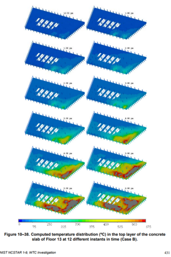
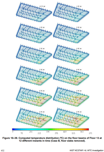
Of course, as I have been saying, applying the temperatures from this single moment in time does not correctly apply the NIST model. Let's look at what actually happened on floor 13 in the NIST model per NCSTAR 1-9, for example:
upload_2017-9-14_16-2-35.png

and

upload_2017-9-14_16-3-29.png

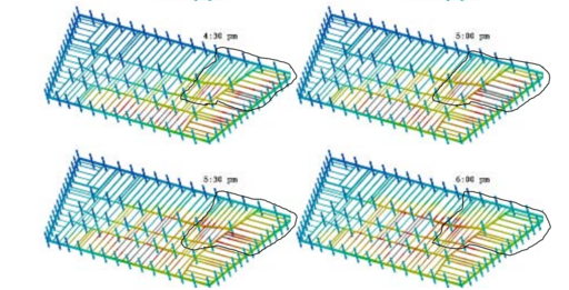
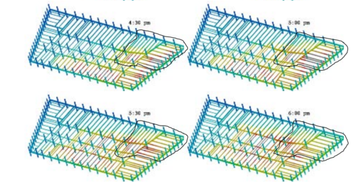
Now let's focus in again on the small area on floor 13 Hulsey purported to model fire damage:

upload_2017-9-14_16-5-5.png

In that area on floor 13, it is clear the hottest beam temperatures DID NOT OCCUR at 6:00 in NIST's simulation (which is the point in time from which Hulsey captured his temperature map). Not only has Hulsey not calculated damage, the effects of which will be path dependent, in the correct sequence, his snap shot of temperatures used on floor 13 at 6:00 comes from AFTER the key beams on the east side had already begun cooling. Their hottest point was 4:30 to 5:30. Hulsey does not account for the damage caused by that period.

Also, it again is worth noting that Hulsey does not account for any damage at all outside of the corner he modeled or on floors other than 12 and 13.
 

Attachments

  • upload_2017-9-14_15-3-44.png
    upload_2017-9-14_15-3-44.png
    434.6 KB · Views: 399
  • upload_2017-9-14_15-5-25.png
    upload_2017-9-14_15-5-25.png
    615.6 KB · Views: 393
  • upload_2017-9-14_15-34-43.png
    upload_2017-9-14_15-34-43.png
    1.1 MB · Views: 400
  • upload_2017-9-14_15-53-41.png
    upload_2017-9-14_15-53-41.png
    1.1 MB · Views: 457
Last edited:
I do not believe your claim that "there's no accounting for any expansion in K3004 to the East". Perhaps there is no explicit mention of this, but it is clear that the gap was in fact modelled. If you want to positively claim that the east of K3004 did NOT push east in NIST's Chapter 11 simulation, you need to present positive proof of it.
What about the COMBIN37 inhibiting any eastward movement, is that not the issue ?
At least you have seen what I am actually getting at now.
 
The project notes are interesting from the Project page. Give a great insight into how the model developed through it's earliest stages. Bottom of the page "Research and Analysis" but it is 1.1 gb and has the whole drawing set attached.
http://www.wtc7evaluation.org/
You mean the "Research Data and Analysis"?

I agree this is interesting - and I thought they would update this frequently, or better yet add more files with updates (it is actually very silly to include all the drawings; they cost most of the 1.1 GB; who in their right mind will download 1.1 GB every month?)

And know what? I beleived that the content of this, how the model developed, was what AE911truth meant when the promised transparency and full access to data at MONEY solicitation time.

Please confirm for us that the newest files in that 1.1 GB are almost 2 years old, and that the very project page that had the promises (removed just a few days ago!) there on the very same page, never carried through with the promise to update the project progress.

Same goes with the lab videos, also linked on the project page - they completely STOPPED making the promised updates in late summer 2015.
 
What about the COMBIN37 inhibiting any eastward movement, is that not the issue ?
Does it? The description references left and right motion. One dimension is not the same as one direction. Maybe it's not a constraint, just a distance trigger.

And again, we've got far less idea about what Hulsey did. Just a couple of graphs of springs.
 
The problem here is that people have touted his qualifications as a part of the evidence. If Hulsey says it, then since he's so well qualified, then it must be true, right? However this example does not give much confidence that his qualifications continue to be relevant at this date.

I disagree! Just like every bit of film I've ever seen of Hulsey he seems like a noble meister, like off Game of Thrones
 
Please confirm for us that the newest files in that 1.1 GB are almost 2 years old, and that the very project page that had the promises (removed just a few days ago!) there on the very same page, never carried through with the promise to update the project progress.

There's a "give input" button too. Maybe use that and ask them. I wasn't there.
 
What about the COMBIN37 inhibiting any eastward movement, is that not the issue ?
At least you have seen what I am actually getting at now.
You make an unsubstantiated claim there ("COMBIN37 inhibiting any eastward movement") which further derails the thread. Stop this.

Please go back to my previous few posts.

You have MANY questions to answer, acknowledge and correct. I am not going to chase your goal posts runing Amok.
 
Does it? The description references left and right motion. One dimension is not the same as one direction. Maybe it's not a constraint, just a distance trigger.

And again, we've got far less idea about what Hulsey did. Just a couple of graphs of springs.
That's what I thought initially re the COMBIN37.
The project isn't finished, so there's time to put meat on those bones. The notes might help you.
 
There's a "give input" button too. Maybe use that and ask them. I wasn't there.
I did, so did Mike, so did, I believe, benthamitemetric.

Guess what happened? NOTHING! Promise broken. It was a scam, a hoax, a fraud, a nothingburger. Gage and Hulsey probably laughing their collective butts off everytime a gullible fool hit that button, believing AE911Truth ever meant to deliver on their promises.
 
I agree this is interesting - and I thought they would update this frequently, or better yet add more files with updates (it is actually very silly to include all the drawings; they cost most of the 1.1 GB; who in their right mind will download 1.1 GB every month?)

I would :) But as you say that file is unchanged since Nov 20 2015. It contains almost nothing besides the public domain plans we already had. Two work diaries, and 11 screenshots.
 
I disagree! Just like every bit of film I've ever seen of Hulsey he seems like a noble meister, like off Game of Thrones
Ok.
If Scientists are more like GoT characters, that inspires confidence...

I suggest that for his next presentation, Hulsey put on a fur coat with macho leather applications and rides in on a dragon. That'll show NIST!
 
Sorry chaps, the COMBIN37 discussion is getting too far off topic (Hulsey's study) - especially as it's largely speculative, since nobody here has practical experience with all modes of usage of a COMBIN37 and we don't know exactly how NIST used it.

So unless there's a direct relevance to Hulsey's study you can take it to PM.
 
Please don't delete this again Mick as it is very on topic.
These break elements are crucial and I think it would inform us to know what type of element NIST used (COMBIN37) and how that may have changed the analysis. I would also then like to put Dr Hulsey's model under the same scrutiny to compare them. I am going through the notes at the moment for any of Dr Hulsey's model details that might be there.
But I think it would do no harm to establish just how many directions a unidirectional element can move in.
As I said earlier, I think it's one, but I am prepared to be wrong.
 
Status
Not open for further replies.
Back
Top