Critical Errors and Omissions in WTC7 Report Uncovered

Status
Not open for further replies.
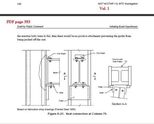
Now that's a critical error/omission! lol. You clearly do not understand what a shear stud is, let alone what function it performs. Also, look at the welding that is called out at the top of the plate.

Now that's a critical error/omission!

Isn't it just.

You clearly do not understand what a shear stud is, let alone what function it performs

Good. Hasn't taken you long to suss out a lack of knowledge masquerading as the opposite. You might like to check Jazzy's 'theory' about the friction welding caused by the threaded floors during the towers' collapses, which in turn transferred enough heat to the bottom of the pile to maintain it at the temps observed for weeks after! It's quite, er, 'remarkable'.

More seriously, though, G - excellent work! I'd agree with Boston on the tidying up and presenting for review. It looks like a slam-dunk to me. I can't find any issues in the detail; so all that remains is really a few drafts to distil the message to its purest possible configuration. It's not far off as it is, but never hurts to finesse to the max.
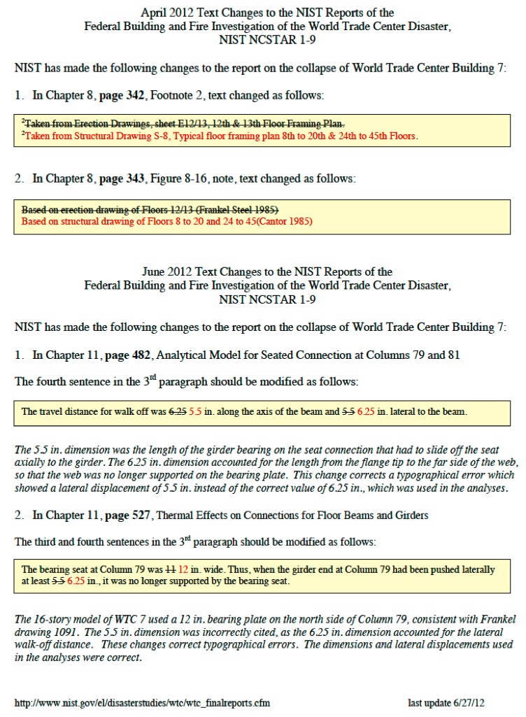
Q: Did you make a request to NIST to issue the erratum sheet after finding the connection detail (12 vs 11) error? (or other?). It's quite astonishing they could make such a basic 'mistake'; add to that the second 'erratum' which just happens to relate to the first directly - as it's the central plank of their whole 'cause of collapse' scenario, can they just change the numbers every time someone points to an obvious error? At the very least this is gross incompetence; but how can you 'mis'read the drawings in your possession and to which you refer for your hypothesis without being guilty of something more than incompetence? Now we know why they didn't want the drawings in the public domain, eh?

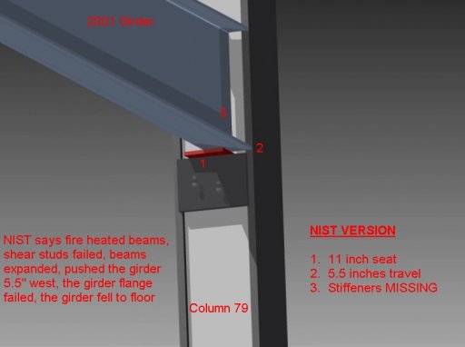
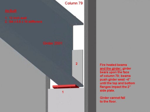
More generally, thinking about it, it would be critical in your presentation to make the point on the temps selected by NIST (ie up to 600C) which again benefits their hypothesis of expansion (but no sagging - which would further kill the idea) to the maximum. And juxtaposing all that information with the changes NIST have recently made re: 11 inches to 12 (for the seat) + 5.5 inches to 6.25 (for the expansion), and the claim of 'typo'/transposition'! I realise you've already indicated such, but think it's worth thinking really hard about exactly how that gets laid out on the page for maximum simplicity/elegance. Obviously, the 'new' 6.25 inch expansion figure is requiring temps beyond which further lateral expansion would be an issue, ie. when sagging comes into play. Also, given that office contents generally burn for a max of 30 mins before moving on, and that NIST themselves claimed in the case of WTC7 that this figure was approx 15 mins - then maybe something along the lines of a temp/time/expansion/sag graph of sorts? Given that the fire-proofing in 7 was intact, from plasterboard to sfrm - worth a mention maybe?

Just a few thoughts - but again, excellent - well done G!

Cheers

ps regarding the shear studs themselves - what are NIST suggesting in relation to those? That the expanding girder w/studs cracked the floor slab or they were sheared? Or do they just avoid it?
 
check Jazzy's 'theory' about the friction welding caused by the threaded floors
That's your myth.

it's the central plank of their whole 'cause of collapse' scenario
I don't believe it is.

(but no sagging - which would further kill the idea)
Uneven expansion and sagging is central to the idea.

office contents generally burn for a max of 30 mins before moving on
As is this.

maybe something along the lines of a temp/time/expansion/sag graph of sorts? Given that the fire-proofing in 7 was intact, from plasterboard to sfrm - worth a mention maybe?
That's a really good idea. Comparing it with the floors above and below would also be a good idea.

This would approach the truth of events much more closely, I think, than a fifth-grade two-dimensional approach lacking a timeline, or a comparison with any other simultaneous event whatsoever, including differential expansions.

Then you might add an overall tension/compression map for perhaps three floors, and adjustments for creep. And, of course, the consequent buckling analysis...

But in AE911T, you aren't going to find those subjects mentioned at all..

Or do they just avoid it?
That's more Gerrycan's topic. He should be able to answer that.
 
NIST corrected the 11 vs. 12 inch thing over a year ago.
http://www.nist.gov/customcf/get_pdf.cfm?pub_id=901225


And they addressed the shear stud issue in the FAQ at the same time:

34. (added 6/27/12) For the WTC 7 16-story model for structural response to fire effects, why did NIST model the girders without shear studs, given that articles published in the open literature showed drawings of typical floor framing plans of WTC 7 with shear studs on the girders?

The source documents used for developing the structural analysis models of WTC 7 were the structural drawings prepared by the structural engineer of record (Irwin G. Cantor, Structural Engineers) and the erection drawings prepared by the steel fabricator and erector (Frankel Steel Limited). Neither the structural drawing for typical floors 8 through 20 (Structural Drawing S-8) nor the erection drawings for floors 10 through 13 (Erection Drawings E10/11 and E12/13) show any studs on the girders. A structural drawing showing modifications to Floor 10 (Structural Drawing S-8-10) to accommodate increased floor loads in certain areas did indicate shear studs for the girders in the affected areas, though the additional load was not identified on the drawing. The modification also indicated reinforcing some floor connections and adding new plates on the bottom flanges of some north and south floor beams.

A paper by J.J. Salvarinas that was published in the Canadian Structural Engineering Conference Proceedings (1986) contained "Figure 5 - Typical Floor Framing" that showed shear studs on the girders, although no reference was cited for the information presented in the figure. The number of shear studs indicated on the floor plan by Salvarinas is similar to, but not exactly the same as, the number of studs indicated on the modified framing plan for floor 10. For typical floors 8 to 20 (excluding floor 10), both structural and erection drawings of WTC 7 obtained by NIST are not consistent with Figure 5 in the Salvarinas paper.

For the 16-story model of WTC 7, NIST did not include shear studs on the girders based on the following reasoning:

(1) The structural floor plans and erection drawings for typical floors are consistent and do not indicate any shear studs on the girders,

(2) The Salvarinas paper did not cite a source for its figure showing "Typical Floor Framing," and

(3) To make the modifications to the framing on Floor 10 would have required accounting for the structural changes shown on drawing S-8-10 (steel plates on bottom flanges of floor beams, shear studs on girders, and reinforced connections), and making the attendant changes to the floor loading in order to be consistent.Since the drawings did not provide any information on revised floor loading or revised connections, this was not possible.
Content from External Source
 
Last edited:
There are errors and omissions in the NIST Report. None of them are in any sense critical. Gerrycan has found one.

An analogy would be that he has discovered that the gash in the side of the Titanic was a little thinner than first thought, which proves that it couldn't have sunk within the time it did.

And secretly he believes that someone let off a bomb attached to a watertight compartment just before the water over-ran it, but he isn't going to tell you that.

And, oh dear, the gash wasn't as thick as originally reported after all.
 
Well they were informed of this quite a while ago Mick. I think the complaint is that they just swapped some numbers around in response to it. Just as you've pointed out.

Go check out how much heat it takes to deform/expand steel to the "new' degree necessary in order to accommodate the NIST hypothesis considering the "correct" ( at least according to the blue prints ) design.

Basically they shoot themselves in the foot by previously drawing a line in the sand by saying temps over x would allow for sag in the beams and not push the girder off its seat. Where as the temp they suggest was just perfect to move the beam y distance assuming there original but incorrect estimate of the seat dimensions. Increase the size of the seat and add web stiffeners and you increase the amount of heat needed to dislodge it, in direct contradiction of what they claim. Course they also forgot that the surrounding structural members were physically in the path of that failure. But thats a whole other issue I think we should take up separately.

PS
its OK to admit when your wrong, kinda makes things a lot easier actually ;-)

Oh and they also forgot to look at that test you presented to me in that other thread. Uneven heating of the steel causes bending long before it has a chance to expand linearly. One side heats and the other does not, the response of the beam is to bend, without much if any push.
 
Last edited:
NIST corrected the 11 vs. 12 inch thing over a year ago.
http://www.nist.gov/customcf/get_pdf.cfm?pub_id=901225


And they addressed the shear stud issue in the FAQ at the same time:

34. (added 6/27/12) For the WTC 7 16-story model for structural response to fire effects, why did NIST model the girders without shear studs, given that articles published in the open literature showed drawings of typical floor framing plans of WTC 7 with shear studs on the girders?

The source documents used for developing the structural analysis models of WTC 7 were the structural drawings prepared by the structural engineer of record (Irwin G. Cantor, Structural Engineers) and the erection drawings prepared by the steel fabricator and erector (Frankel Steel Limited). Neither the structural drawing for typical floors 8 through 20 (Structural Drawing S-8) nor the erection drawings for floors 10 through 13 (Erection Drawings E10/11 and E12/13) show any studs on the girders. A structural drawing showing modifications to Floor 10 (Structural Drawing S-8-10) to accommodate increased floor loads in certain areas did indicate shear studs for the girders in the affected areas, though the additional load was not identified on the drawing. The modification also indicated reinforcing some floor connections and adding new plates on the bottom flanges of some north and south floor beams.

A paper by J.J. Salvarinas that was published in the Canadian Structural Engineering Conference Proceedings (1986) contained "Figure 5 - Typical Floor Framing" that showed shear studs on the girders, although no reference was cited for the information presented in the figure. The number of shear studs indicated on the floor plan by Salvarinas is similar to, but not exactly the same as, the number of studs indicated on the modified framing plan for floor 10. For typical floors 8 to 20 (excluding floor 10), both structural and erection drawings of WTC 7 obtained by NIST are not consistent with Figure 5 in the Salvarinas paper.

For the 16-story model of WTC 7, NIST did not include shear studs on the girders based on the following reasoning:

(1) The structural floor plans and erection drawings for typical floors are consistent and do not indicate any shear studs on the girders,

(2) The Salvarinas paper did not cite a source for its figure showing "Typical Floor Framing," and

(3) To make the modifications to the framing on Floor 10 would have required accounting for the structural changes shown on drawing S-8-10 (steel plates on bottom flanges of floor beams, shear studs on girders, and reinforced connections), and making the attendant changes to the floor loading in order to be consistent.Since the drawings did not provide any information on revised floor loading or revised connections, this was not possible.
Content from External Source

And here is the video on my original channel (unlisted) uploaded on Feb 4th 2012. Nice try though. We spent a long time checking our work, and we are now at the stage where we have further checked and rechecked, and are preparing further releases and as suggested a written summary of our findings.
Some of the comments I am getting on here are really helping with that.
As you can see in the videos, we allowed for no resistance due to shear studs and the connection still did not fail. That the girder did or didn't have shear studs makes no difference, but I would still reckon it would have them. The floorpan installer would agree with this, as would every other engineer i have ever managed to speak to about this. It is common sense that the floor would be made composite by their use. But just to be clear, before i go further, you now accept that every floor beam to the east of the connection had shear studs on it?
 
Last edited by a moderator:
You say (and I really wish you'd write this down). "if the shear studs were used between these elements and the concrete that made up the floors, it is difficult to imagine how the alleged expansion could possibly have occurred"

Can you explain that? If steel is heated then it expands. Now what exactly would the effect of the shear studs be on that expansion? Can you actually stop steel expanding by holding it in place?
 
If I remember concrete and steel have similar expansion and contraction rates, which is one reason its such a good combination for structural design. Things like bridges that undergo a lot of thermal expansion. The deck system would have moved as one regardless of the heat, as long as things had a chance to heat up evenly, although heat deformation of the steel due to uneven heating might have resulted in some cracking of the concrete, which by the way still leaves all that welded mesh and corrugated decking. Which is kinda why they are there, cause cracks are inevitable in a large slab. The sheer studs wouldn't really be effected, as the cracking of the slab seldom follows the path of the structural support, silly as it sounds, it tends to follow the path between two temp variations. Like where sunlight on one the south side effects the slab unevenly. In the end you'd be surprises just how flexible concrete is.

There's pretty much not a single slab on a single floor of any steel framed building that doesn't have a whopping huge crack running smack through the middle of it somewhere. Its expected adn accounted for in the design.

I find it reasonable to expect that the slab would have resisted the expansion of the steel at least until the slab itself had a chance to heat up, in that resistive phase there may have been some fracturing of the slab. However the heat is being applied to the underside of the beams which makes them want to sag towards the heat. This sag will pull on the slab rather than push it IMHO. So the slab and all its connective tissues ends up supporting the beams in question.
 
Last edited:
You say (and I really wish you'd write this down). "if the shear studs were used between these elements and the concrete that made up the floors, it is difficult to imagine how the alleged expansion could possibly have occurred"

Can you explain that? If steel is heated then it expands. Now what exactly would the effect of the shear studs be on that expansion? Can you actually stop steel expanding by holding it in place?
It's impossible without the studs, never mind with them. As Boston said, concrete and steel have similar thermal expansion coefficients, the difference is in their ability to conduct heat. I think a good way to think of the function of the studs is to make the floor system act as one element ie composite. NIST supposed that the steel heated up, but the concrete didn't. This sets up a differential thermal expansion between them and would allow them to ignore the composite nature of the floor system. You cannot stop steel expanding and if it is held in place either at the ends or also with studs it would go into compression. The issue here is that NIST played down the studs on the beams. Studs on the girder is a different issue.
Interesting to note that they have not let us see the FW (fieldwork) drawings, and that the drawings that they have let us see (which are not complete) refer to field applied studs. Who is to say that there were not studs applied at the fabrication shop? Maybe that was what Salvarinas was referring to. Given that, as you said, the studs he specified are not on the drawings released so far, that he would include them as part of his presentation. So you think he took a base drawing and them added the studs to that drawing manually?
Also interesting to note that the girder in question does have studs at some floors indicated at some floors, according to the drawings that we have. So why not on floor 13?
 
If I remember concrete and steel have similar expansion and contraction rates, which is one reason its such a good combination for structural design.

You do remember right.

(10-6 m/m K) *)

Concrete @ 14.5
Steel @ 13.0

edit - that's coefficient of linear thermal expansion.
 
Interesting to note that they have not let us see the FW (fieldwork) drawings, and that the drawings that they have let us see (which are not complete) refer to field applied studs. Who is to say that there were not studs applied at the fabrication shop? Maybe that was what Salvarinas was referring to. Given that, as you said, the studs he specified are not on the drawings released so far, that he would include them as part of his presentation. So you think he took a base drawing and them added the studs to that drawing manually?
Also interesting to note that the girder in question does have studs at some floors indicated at some floors, according to the drawings that we have. So why not on floor 13?

Are there any specs to go with the drawings, G? Or bill of quantities from the QS? I can't believe the drilling for studs would be done on site - fitted, quite possibly, but the shop drawings might show the numbers of studs/holes to be drilled specified for each element requiring....?
 
Are there any specs to go with the drawings, G? Or bill of quantities from the QS? I can't believe the drilling for studs would be done on site - fitted, quite possibly, but the shop drawings might show the numbers of studs/holes to be drilled specified for each element requiring....?
There are some specs on drawings, welding electrodes to be used etc etc, but not a lot re shear studs, the notes on E12/13 specify field applied studs, which would be put in place before the concrete is poured obviously. There were some renovations carried out a few years after which called for more studs to be added on the beams further south of column 79, and these would have been added by drilling out a core, adding the stud to the beam, then refilling the hole with concrete. I have a drawing for this somewhere, and it also shows a substantial mesh added above the beams and girders. Just for some light relief in the meantime, here's a video we did last week.............
 
It's impossible without the studs, never mind with them. As Boston said, concrete and steel have similar thermal expansion coefficients, the difference is in their ability to conduct heat. I think a good way to think of the function of the studs is to make the floor system act as one element ie composite. NIST supposed that the steel heated up, but the concrete didn't. This sets up a differential thermal expansion between them and would allow them to ignore the composite nature of the floor system. You cannot stop steel expanding and if it is held in place either at the ends or also with studs it would go into compression. The issue here is that NIST played down the studs on the beams. Studs on the girder is a different issue.?

So what exactly would the effect of the studs be in this situation? Would the beams expand any less? Differently?
 
Are there any specs to go with the drawings, G? Or bill of quantities from the QS? I can't believe the drilling for studs would be done on site - fitted, quite possibly, but the shop drawings might show the numbers of studs/holes to be drilled specified for each element requiring....?

Its been a while but as I remember these studs aren't drilled, they welded to the top of each beam with a special tool, oh and the guys who run that tool just hate it. Its back breaking and you gotta carry a hundred pounds of studs around with you. They have a name for the tool but I'd likely get canned for posting it on here :D
 
They tie the slab system to the support system. Creating a monolithic construct that acts as one unit under load. One thing they would certainly do is help in heat transfer from the beam to the slab. It'd be like a radiator actually, dissipating the heat of slow burning office fires throughout the system.
 
You do remember right.

(10-6 m/m K) *)

Concrete @ 14.5
Steel @ 13.0

edit - that's coefficient of linear thermal expansion.

Those figures are at:
http://www.engineeringtoolbox.com/linear-expansion-coefficients-d_95.html

Note that's in K (Kelvin, essential Celsius in this usage). Multiply by 5/9 to get the coefficient for F. (The m/m or in/in notation is irrelevant)

However I've seen values of 12.0 bandied around for both steel and concrete, and for some reason I remember NIST using 10 and 12, but can't remember where.

This gives:
http://en.wikipedia.org/wiki/Thermal_expansion#Thermal_expansion_coefficients_for_various_materials

Carbon Steel 10.8
Concrete 12
Steel 11-13
Content from External Source
 
They tie the slab system to the support system. Creating a monolithic construct that acts as one unit under load. One thing they would certainly do is help in heat transfer from the beam to the slab. It'd be like a radiator actually, dissipating the heat of slow burning office fires throughout the system.

Yeah I know, but how would it affect the expansion of the beam?
 
Its been a while but as I remember these studs aren't drilled, they welded to the top of each beam with a special tool, oh and the guys who run that tool just hate it. Its back breaking and you gotta carry a hundred pounds of studs around with you. They have a name for the tool but I'd likely get canned for posting it on here :D

You're right!
 
Those figures are at:
http://www.engineeringtoolbox.com/linear-expansion-coefficients-d_95.html

Note that's in K (Kelvin, essential Celsius in this usage). Multiply by 5/9 to get the coefficient for F. (The m/m or in/in notation is irrelevant)

However I've seen values of 12.0 bandied around for both steel and concrete, and for some reason I remember NIST using 10 and 12, but can't remember where.


Depends on type of concrete - anything from 7 to 16 - aggregate type has quite a bit to do with it. Point is - steel and concrete are close in thermal expansion - less so in temp gain
 
Its been a while but as I remember these studs aren't drilled, they welded to the top of each beam with a special tool, oh and the guys who run that tool just hate it. Its back breaking and you gotta carry a hundred pounds of studs around with you. They have a name for the tool but I'd likely get canned for posting it on here :D

A Stud Gun (although I can imagine a variety of embellishments)
 
http://www.engr.psu.edu/ce/courses/...ermalexpansioncontraction/thermalexpcontr.htm


When free to deform, concrete will expand or contract due to fluctuations in temperature. The size of the concrete structure whether it is a bridge, a highway, or a building does not make it immune to the effects of temperature. The expansion and contraction with changes in temperature occur regardless of the structure’s cross-sectional area.

Concrete expands slightly as temperature rises and contracts as temperature falls. Temperature changes may be caused by environmental conditions or by cement hydration (the exothermic chemical process in which the cement reacts with the water in a mixture of concrete to create the calcium silicate hydrate binder and other compounds). An average value for the coefficient of thermal expansion of concrete is about 10 millionths per degree Celsius (10x10-6/C), although values ranging from 7 to 12 millionths per degree Celsius have been observed. This amounts to a length change of 1.7 centimeters for every 30.5 meters of concrete subjected to a rise or fall of 38 degrees Celsius.

Thermal expansion and contraction of concrete varies primarily with aggregate type (shale, limestone, siliceous gravel, granite), cementitious material content, water cement ratio, temperature range, concrete age, and ambient relative humidity. Of these factors, aggregate type has the greatest influence on the expansion and contraction of concrete.

Severe problems develop in massive structures where heat cannot be dissipated. Thermal contraction on the concrete’s surface without a corresponding change in its interior temperature will cause a thermal differential and potentially lead to cracking. Temperature changes that result in shortening will crack concrete members that are held in place or restrained by another part of the structure, internal reinforcement or by the ground. For example, a long restrained concrete section is allowed to drop in temperature. As the temperature drops, the concrete tends to shorten, but cannot as it is restrained along its base length. This causes the concrete to be stressed, and eventually crack.

Joints are the most effective way to control cracking. If a sizable section of concrete is not provided with properly spaced joints to accommodate temperature movement, the concrete will crack in a regular pattern related to the temperature and restraint directory. Control joints are grooved, formed, or sawed into sidewalks, driveways, pavements, floors, and walls so that cracking will occur in these joints rather than in a random manner. Contraction joints provide for movement in the plane of a slab or wall, and induce cracking caused by thermal shrinkage at preselected locations. One of the most economical methods for making a contraction joint is by simply sawing a continuous cut in the top of the slab with a masonry saw.


Content from External Source

Bit more detail than my memory

Edit: so looks like NIST took the average - 10 - when actually we know that the mixes had 3/4 inch Haydite as aggregate (in the towers, anyway) - (like perlite) - so would that be 10, I wonder?
 
Last edited by a moderator:
The studs act like fins on a radiator and dissipate heat to the concrete. They also mechanically tie the beam to the slab which means they tend to expand and contract together as a monolithic structure. Surprisingly enough the slab can add a significant amount of strength to the floor system because its embedded with a steel mesh, sometimes several layers that lap all the corrugated pan joints, or are supposed to. Also depending on the span there is rebar involved as well, which you might find interesting is often tied off to the studs. They make convenient risers, although this is not how its supposed to be done.
 
yah, expansion joints are mostly around columns and exteriors, they tend to use control lines mid slab, I think I even have a lining tool around here somewhere. Another job you never want to have to do.
 
The studs act like fins on a radiator and dissipate heat to the concrete. They also mechanically tie the beam to the slab which means they tend to expand and contract together as a monolithic structure. Surprisingly enough the slab can add a significant amount of strength to the floor system because its embedded with a steel mesh, sometimes several layers that lap all the corrugated pan joints, or are supposed to. Also depending on the span there is rebar involved as well, which you might find interesting is often tied off to the studs. They make convenient risers, although this is not how its supposed to be done.

But what effect would the studs have on the expansion of the beams in this circumstance? Assuming heated as described by NIST.
 
As an interesting aside, now that NISTs 'theory' as to what initiated the collapse of WTC7 is in shreds, it would be interesting to see somebody propose how fire can actually remove 108ft of resistance in the building and cause this to happen.
 
As an interesting aside, now that NISTs 'theory' as to what initiated the collapse of WTC7 is in shreds, it would be interesting to see somebody propose how fire can actually remove 108ft of resistance in the building and cause this to happen.

In shreds? Methinks you are being a little hasty. Perhaps you should at the very least write down your rebuttal before calling it?
 
In shreds? Methinks you are being a little hasty. Perhaps you should at the very least write down your rebuttal before calling it?
Ok, we have a plate (pf) that NIST said was 11" when it was 12". We have a plate (pg) that was omitted from their analysis. We have 2 stiffener plates that were ignored. We have a new proposed walk off distance that NIST themselves say would need a temp at which steel would lose tensile strength to the extent that it would sag, making the push impossible. And on top of that we have an ANSYS FEA model which they will not release the input data for. I could go on....... Their theory is clearly torn to shreds, and can be discarded. What makes you cling to the impossible?
 
yah, expansion joints are mostly around columns and exteriors, they tend to use control lines mid slab, I think I even have a lining tool around here somewhere. Another job you never want to have to do.

In the NIST reconstruction (for concrete fire performance) the pics showing the concrete pour show areas shuttered off in approx 10 foot x 10 ft squares, presumably for expansion joints - with (in uk) A393 mesh (or US equivalent) - that might be for towers rather than 7, would make more sense given the flex required. But still, this type of detail would be good to have - as G has shown - with the right information, progress can be made!
 
Ok, we have a plate (pf) that NIST said was 11" when it was 12". We have a plate (pg) that was omitted from their analysis. We have 2 stiffener plates that were ignored. We have a new proposed walk off distance that NIST themselves say would need a temp at which steel would lose tensile strength to the extent that it would sag, making the push impossible. And on top of that we have an ANSYS FEA model which they will not release the input data for. I could go on....... Their theory is clearly torn to shreds, and can be discarded. What makes you cling to the impossible?

G, know it's a drag, but could we have a side by side fig 1 and fig 2 of Nist's representation of the connection and the drawing's?
 
But what effect would the studs have on the expansion of the beams in this circumstance? Assuming heated as described by NIST.

It would slow down the expansion due to the studs acting like the fins of a radiator and transferring heat away from the beam
 
Ok, we have a plate (pf) that NIST said was 11" when it was 12". We have a plate (pg) that was omitted from their analysis. We have 2 stiffener plates that were ignored. We have a new proposed walk off distance that NIST themselves say would need a temp at which steel would lose tensile strength to the extent that it would sag, making the push impossible. And on top of that we have an ANSYS FEA model which they will not release the input data for. I could go on....... Their theory is clearly torn to shreds, and can be discarded. What makes you cling to the impossible?

Because your case seems very weak so far. You've claimed there must be shear studs even though they don't appear on the sheets for that floor, then even if they are there you don't seem very clear on what effect they would have on the expansion (and radiating heat I assume is not something you think is particularly significant). Then you complain about a plate size that NIST corrected a year ago.

And I've not even looked at your "impossible push" math yet. Sorry, but I find video evidence very hard to work with.
I will try to get the above post to work, sorry but i am not used to this format.
Are you saying that the drawings show no studs on the beams??
 
Because your case seems very weak so far. You've claimed there must be shear studs even though they don't appear on the sheets for that floor, then even if they are there you don't seem very clear on what effect they would have on the expansion (and radiating heat I assume is not something you think is particularly significant). Then you complain about a plate size that NIST corrected a year ago.

And I've not even looked at your "impossible push" math yet. Sorry, but I find video evidence very hard to work with.

Think you missed the complete misrepresentation of the connection - the temp effects on steel, re: expansion v sagging - the claim of a 'typo' LOL! - and an incorrect transposition relating to the same typo, relating directly to the central plank of Nist's collapse theory, column 79 - apart from that - you're on the money. Is it really so hard to admit being wrong?
 
I will try to get the above post to work, sorry but i am not used to this format.
Are you saying that the drawings show no studs on the beams??

The drawings for floor 17 that I saw did not. Although to be fair it looked like a strange omission.
 
This is the best I can do for now, I will try to get to it and improve this.....

NIST missing the stiffeners


Stiffeners_Absent_Report 1-9_Fig_8-21.jpg Stiffeners_Inserted_Report 1-9_Fig_8-21.jpg
 

Attachments

  • Stiffeners_Absent_Report 1-9_Fig_8-21.jpg
    Stiffeners_Absent_Report 1-9_Fig_8-21.jpg
    34.7 KB · Views: 516
  • S1C3_NISTversion.jpg
    S1C3_NISTversion.jpg
    132.7 KB · Views: 475
  • S3C3_AsBuilt1.jpg
    S3C3_AsBuilt1.jpg
    106.1 KB · Views: 456
The drawings for floor 17 that I saw did not. Although to be fair it looked like a strange omission.
Ok, I think that can be cleared up fairly easily. It is misleading as different frawings show different detail.....
Shear studs are shown in <> brackets as seen on this note from E12/13 (floor framing plan for 12/13)
Revision_I_B.jpg

Revision_I_B.jpg
Here they are shown on the beams in question <24> / <28>
1213Expansion_all columns_beam.jpg

Don't be confused by the () numbers, which are camber indications
 
Well thats clear as a bell.

And as I read it that materials call out clearly shows a 12" plate, not a 11" plate.
 
Here is the whole E12/13 with no annotations, this is a better one for you to check:-

There are 28 called for on the K3004 also, but the annotation obscured it, sorry if this caused any confusion.
 

Attachments

  • wtc7frankele1213.png
    2.4 MB · Views: 474
Status
Not open for further replies.
Back
Top