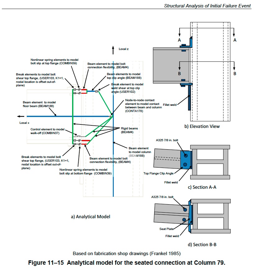
Analytical Model for Seated Connection at Columns 79 and 81
The analytical model for the seated connection at Column 79 is shown in Figure 11–15. The same model
was used for Column 81, but the girder was connected to the column at a different angle. Also note the
difference in the location of the fillet weld―it was at the top of the top clip angle for Column
79―relative to the fillet weld along the sides of the angle in the STC connections at the exterior columns.
The top clip angle used in STC connection at Column 79 and Column 81 was weak in tension and needed
to be explicitly represented in the connection model. Therefore, the failure of the connection was
governed by tension failure of the top clip angle or bolt shear followed by beam walking-off the seat and
loss of vertical support. The analytical model accounted for: 1) shear failure of individual bolts, 2) beam
walking off of the seat, and 3) horizontal weld failure of the top flange clip angle. The failure of the
connection was governed by bolt shear followed by walk-off before loss in vertical support.
At each bolt location one break element, one elastic beam, and one non-linear spring were defined. The
bolt shear strength was modeled with break element type USER103 with K1 = 1, i.e., failure occurred
when the SRSS of the horizontal force components in the x- and y-directions exceeded the temperature dependent
shear capacity of the bolt. The elastic beam represented the stiffness of the bolt connection.
The non-linear spring was used to capture slip in the connection before bolt bearing against the hole edge.
Slotted bolt holes were used at the top flange clip angle while standard bolt holes were used at the bottom
seat plate.
A node-to-node contact element with an initial gap representing the clearance between the end of the
beam and the column was used to model the contact between the beam and the column when the bolts
sheared off and the beam moved enough to touch the surface of the column. The bolts could fail in shear
under a tensile, compressive or lateral force, but the beam would only walk off the seat under a tensile or
lateral force. The failure of the bolts and weld was a prerequisite for the beam end walking off the seat.
The travel distance for walk off was 6.25 in. along the axis of the beam and 5.5 in. lateral to the beam. A
walk off failure occurred when the bolts sheared at the seat connection, the bolts sheared or the weld
failed at the top clip angle, and the beam walked off the seat. A control element was used to model beam
Walk-off in the axial direction. Beam walk off in the lateral direction was monitored during the analysis.