3D Analysis of the Yemen Orb

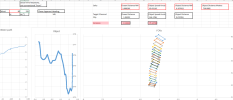
Illustrating my post # 38 concerns, to provide additional context on why this is an issue.

In post #9 I used this graphic, demonstrating that a heading calculated on the N value and the Mag Value has significant deviation.

OGGORC9R.jpg


With the, potential, identification of the reaper heading in the top right box, I take this opportunity to illustrate the variance between both methods and those reported figures.

Screenshot (3257).png


Now I have an opinion that the variance we see here can be based on a few factors,

A. The N value isn't fluid, it appears to "step" through the frame, as if it is updating in 1-3 degree increments,
B. Inaccurate extraction of the data by myself, I used key frames at roughly 30 frame increments, and I can refine that by decreasing that parameter.

Screenshot (3258).png

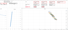
Now, when we seek the variance between the Mag value plus Az heading to the reported heading figures in the top right, we can see, once again, a significant difference.

I have run some prelim numbers and I can rule it out being a distance value, it sought of matches a later frame, but does not fit for the zoomed in version.
Screenshot (3259).png


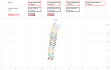
As this is a critical factor in the recreation, I am seeking feed back and opinion about,

1. The heading figure at the top right of the display,
2. Clarification on the relationship between the Magnetic direction and the North value on the overlay of the video,
3. Confirmation that the M value is the magnetic heading direction the camera is looking,

Many thanks for your time.
 
Thank you for your kind words, I truly appreciate them.

As the recreation Mick has placed in is locked on the object, and the footage we have is locked, not locked on the target and is recorded on a mobile phone (you can see the person filming in the reflection) I was having issues trying to understand the motion so I juxtaposed the footage, stable on the object, with a recording of the recreation.


Source: https://www.youtube.com/watch?v=qjksXlDJeb4


Some motion is required and with future updates, we can certainly refine this.

I am in complete agreeance with you, lets squeeze as much info as we can and see what the data tell us, I am not up to background motion expressly, and I do background vectors a little different to Edward, as with this from Go-fast. (this part may be off topic, if so please remove it, I only raise this as a demonstration of methodology/ techniques for the purpose of recreations, and I don't have it in my excel currently)

Screenshot (3263).png

In which Field of views are calculated on the frames where we see the changes, identifying the direction of the path, and checking to see if the edges line up and also identifying likely wind and direction affecting the aircraft.

Screenshot (3264).png

Like in this example, same figures, only difference being wind direction, we can rule it out, as that wind direction results in significant overlap.

I believe the Reaper camera is mounted significantly different to ATFLIR, and there should not be rotation due to camera roll.
 

Attachments

  • Screenshot (3262).png
    Screenshot (3262).png
    144 KB · Views: 43
  • Screenshot (3261).png
    Screenshot (3261).png
    136.1 KB · Views: 37
  • Screenshot (3214).png
    Screenshot (3214).png
    50.9 KB · Views: 50
Hi Chris. I didn't realize that's what it was.

There's a handy explanation of bullseye references here:
https://codex.uoaf.net/index.php/Bullseye
External Quote:
The BULLSEYE is a fixed reference point on the map that is known to all flights from which the position of an object can be referred to by bearing and range. A position is then referenced like a BRAA, but relative to the bullseye instead of any plane
So 19X/32 means it's 32NM SSW of the bullseye, moving from 198° to 194°.

The target goes from 190°, jumping to 189° when switching from object to ocean, and then tracking the ocean back to 190°

This all seems reasonably consistent with the Sitrec recreation, except right at the end the TGT range goes from 29 to 30, which is in the opposite direction. But at this point it's just the ocean.

These numbers are all very rough. 1° at 30NM is 0.5NM.

View attachment 84140
Hi Mick,
Yes, this is roughly correct. Obviously better if we had the ranges but still it puts a minimum and maximum on the positions and it is ground stabilized.

Another point to consider for the drone is the true airspeed. At 24,500' the drone's 200kias will be approximately 367knots true based on 90-degree day. True is approximately 1.62 times the indicated so that will also put a min and max on the drone airspeed.
 
It will still be hot.

What we are seeing in the video is motion blur, not the actual shape of the object.

Look at two consecutive frames overlaid. View attachment 84141
The waves are totally motion-blurred, and there's little to no gap between frames.

The missile overlaps, which I guess means there's some glare making the image bigger than it is
View attachment 84142

But going back to speed, perpendicular to the camera it's travelling about 2 feet in 1/30th of a second. so 60 feet/second, roughly 40 mph, or 18 m/s (very rough)

Also, very rough, the speed of the missile could be reduced to around 250 m/s or less by impact, so this suggests a pretty small angle between the line of sight and the missile trajectory. Possible the drone taking the video is the same one that fired the missile.
Highly doubtful the drone taking the video is the lasing drone. First, the angles are off for tactics. The missile would likely not see the laser energy from the opposite side. Although possible we wouldn't do it on purpose. Much higher probability of hit to have the shooter lase the target in this engagement.
Also we see LRD, meaning Laser Range Designator, not target.
Also, since targeting lasers are not eye safe and critical for weapons employment they usually flash and give more indication they are firing.
 
This was obtained from this YouTube video and should be cued up.


Source: https://youtu.be/JQ4RalNSjJk?t=181


Credit to "Wingnut" YouTube channel

A sidewinder is a very different missile, designed for air-to-air combat, than a hellfire. They go much faster, 2.5+mach and have radar proximity fuses linked to light fragmentary warheads. The modern ones are highly maneuverable.
Hellfires are mainly subsonic missiles designed for air-to-ground anti-tank employment from Apaches. They use impact fuses and are designed for armor penetration and explosion.This should be taken into account for comparisons.
Using Hellfire on air targets is outside the design considerations.
 
I added a new tool to Sitrec, the "Background Flow Indicator" which draws an arrow in the direction of the motion of the background, and a shorter arrow in the same direction that indicates how much the background will move in the next frame.
2025-09-21_13-17-27.jpg


Combining this with the "Vid Overlay Trans" (Video overlay transparency), you can more easily sync the motion. It's also useful in refining the FOV, which I now have at 0.123° vertical, using the attached FOV track file.

I adjusted the target position until the motions were exactly parallel.

https://www.metabunk.org/sitrec/?cu....com/1/Yemen Static Object/20250921_205140.js

This gives a remarkably accurate match for the tracked portion of the video with a perfectly static object, from frame 0
2025-09-21_13-21-55.jpg


To the impact at 596
2025-09-21_13-22-59.jpg


After that point, the camera is not tracking the object exactly, so it's a bit harder to match; Also the object is likely slowly descending. The post-impact potion is 30 seconds. It's hard to say how much it might be descending, but a few experiments with dropping things suggest something less than 10 feet per second terminal velocity for a relatively lightweight object (and the debris), so under 300 feet is reasonable, but maybe 1000 feet to be conservative.

The target altitude is 12168, reducing this to 11168 makes very little difference in the resultant apparent motion. In fact, even a very large drop like 5,000 feet is difficult to detect the effect in the latter portion

Refining the data is certainly worth doing, but ultimately we have to match the video. This is looking very like a near-static object.
 

Attachments

Last edited:
Highly doubtful the drone taking the video is the lasing drone. First, the angles are off for tactics. The missile would likely not see the laser energy from the opposite side. Although possible we wouldn't do it on purpose. Much higher probability of hit to have the shooter lase the target in this engagement.
But the slow speed of the missile on screen, and the decrease in size while it is visible, suggests it's coming in at a steep angle from this side, like the first of these two impacts:


Also we see LRD, meaning Laser Range Designator, not target.

It says DES, meaning designating a target. Wouldn't it say RNG, if it were just ranging?
iran-us-drone-hack.png
 
Also, since targeting lasers are not eye safe and critical for weapons employment they usually flash and give more indication they are firing.
Thank you Chris for your valuable time and insight, that is what, available, footage of a Hellfire hitting a truck displays.

We can see the pulsating.


Source: https://www.youtube.com/watch?v=S_nJovjv-yw

In that footage we can also see how the N value changes yet the M value (reportedly magnetic value, does not alter).

I am also including this footage (as actual reaper footage that ISN'T the training program is hard to locate). We see a number of items onscreen that are consistent with the Yemen encounter footage, Slant range, Ground range


Source: https://youtu.be/flJTAOhlH9E?t=332


[Edit to include additional footage and commentary about it]
 
Last edited:
But the 5M does not appear to be a bearing. I think here it's a dimension for the box. Simialr to FVW and FVH (Field of View Width and Height) here:
The point Mick West is using

That N near the box is most certainly north but I think ya'll figured that out by now lol.

That image gives the aircrafts altitude and position. We also know the target position and aircraft heading. Seems like a good opportunity to verify some assumptions.

I've messed up the distance calculation three times now. I'm going to bed. I managed to get a gound distance of 9 million meters which I don't think is right.

The target's coords are 45°04'59.9"N 83°33'05.7"W (45.083298, -83.551577)

The aircraft's location is 45°06'50.4" N83°43'11.5"W (45.11400000, -83.71986111)

Altitude appears to be 20,074 feet AGL

Edit: Sleep is for the weak.
Ground distance to target: 13.646km
Camera Bearing: 104.49
Camera Declination: 65.85°

I think the bearing kinda lines up with the top two numbers if 69 is the aircraft heading and 37 is the camera. That would be a total of 106 which is a bit off.
 
Last edited:
Now I have an opinion that the variance we see here can be based on a few factors,

A. The N value isn't fluid, it appears to "step" through the frame, as if it is updating in 1-3 degree increments,
B. Inaccurate extraction of the data by myself, I used key frames at roughly 30 frame increments, and I can refine that by decreasing that parameter.
I think the bearing kinda lines up with the top two numbers if 69 is the aircraft heading and 37 is the camera. That would be a total of 106 which is a bit off.

Here's the clip


And in Sitrec
https://www.metabunk.org/sitrec/?cu...s.com/1/MQ_9s Viewing A10s/20250922_065457.js

I think we can see from this that neither set of numbers is incredibly accurate.
It starts ouf 70+34 = 104, with BRG 104, which is great.
But then we have 70+36 = 106, but BRG remains 104.
Later 72+37 = 109, but BRG = 105
 
All good points and thank you to @boguesuser for highlighting that we can use those videos to test methodology.

Thank you @Mick West for the updated link to the SITREC

https://www.metabunk.org/sitrec/?custom=https://sitrec.s3.us-west-2.amazonaws.com/1/Yemen static normal map/20250922_153523.js

A cursory viewing it looks consistent with the footage, noting the obvious limitations. I haven't been able to go any further than that.

Not wanting to hold you up in making your position public, I have nothing to counter this with currently, as I am still reconciling the heading figures, working out the additional information by using the bullseye reference points, like heading, velocity of the reaper. As mentioned in private, I have commitments until the weekend that don't allow for me to contribute until then.

[edit - edited to include the caveat ", noting the obvious"]
 
Last edited:
But the slow speed of the missile on screen, and the decrease in size while it is visible, suggests it's coming in at a steep angle from this side, like the first of these two impacts:
Is it possible to add a speculative missile trajectory to the simulation? Let's assume for a moment that the Hellfire was fired from the same drone that was also filming. We know approximately when it would have had to be launched under that assumption. It would be interesting to see whether the apparent "S-shaped" trajectory—sometimes described as the missile "bouncing off" the target—could actually be explained by the movement of the camera relative to the background. The fact that the target sits perfectly in the middle of the "S" suggests this might be more a result of camera movement than the missile's actual path.

IMG_6032.jpeg
 
Is it possible to add a speculative missile trajectory to the simulation?
It's on my list of things to do. Unlikely to be done soon.


The fact that the target sits perfectly in the middle of the "S" suggests this might be more a result of camera movement than the missile's actual path.
I can't quite see how, but it would be an interesting thing to test.

The missile isn't going to take a straight line path. It's not pointing in the right direction at the start, so at the very least, there would be an initial curve. I suspect the curve the other way after "impact" is just its tracking being a bit confused.
 
The missile isn't going to take a straight line path. It's not pointing in the right direction at the start, so at the very least, there would be an initial curve. I suspect the curve the other way after "impact" is just its tracking being a bit confused.
Yeah, you're absolutely right. But we only see the alleged Hellfire for about a second before impact, and by that point it should already be heading toward the target with minimal adjustment. It's really difficult to picture the scene in 3D, but there's something about that S-shaped trajectory that feels a bit strange and off.
 
Yeah, you're absolutely right. But we only see the alleged Hellfire for about a second before impact, and by that point it should already be heading toward the target with minimal adjustment. It's really difficult to picture the scene in 3D, but there's something about that S-shaped trajectory that feels a bit strange and off.
This post in the other thread might help:
https://www.metabunk.org/threads/uap-hearing-new-video-yemen-orb.14427/post-353035


img_3974-dots-gif.84376


All three lines are the same length. All three dots move at the same constant speed. The middle one is only slightly bent.
 
All three lines are the same length. All three dots move at the same constant speed. The middle one is only slightly bent.
Thanks, that's a great illustration! Especially, it perfectly illustrates why the missile appears to be traveling unusually slowly in the video!
 
I corrected the handheld camera distortion for chosen frames by manually aligning the "corners" to the corresponding "corners" in a frame from ME24 :
1759068476916.png


I extracted the N angle and the other visible data from the corrected frames :
1759068552458.png


I thought it looked like constant speed/heading drone and UAP so I computed a straight line trajectory for the drone in the UAP frame of reference (static object scenario) from the data :
1759068751833.png


In blender, I animated this scenario for the drone. I attached the camera to the drone and set up the camera to automatically track the UAP at the origin point.
I set up a HUD to display the different angle in ranges as in the source video. All the numbers in my HUD are computed from the position of objects in blender, nothing is animated.
Here's the result for the first 595 frames (until the impact and tracking is lost) :


Mostly within 1° or 0.1 NM compared to the original video. I think if the source video had more resolution for the N angle and more visible digits for the ranges I'd be able to get even closer.
 
I found a way to emulate a smaller FOV in blender so I could use the real FOV (0.115) for the missile trajectory.
I found a straight line trajectory (redish dot) that is a good match for the missile trajectory :

But this give a surprisingly low speed for the missile : 112 m/s | 404 km/h | 218 knots | 251 mph, which is way slower than the hellfire's Mach 1.3.
Other FOVs and/or straight lines trajectories don't give good matches.
I must have messed up somewhere but can't find where.

Is there a quick way to get a sitrec going from a few x,y,z coordinates or do I need to convert everything to fake lat,long,alt in a .kml ?
 
I must have messed up somewhere but can't find where
I found a mix-up between the horizontal and vertical FOV. I fixed it and programmed the camera projection in excel for comparison purposes. Here's the result, a dot every 5 frame from 566 to 596 :
1759947092679.png

I get a missile speed of 181 m/s | 653 km/h | 353 knots | 406 mph

If someone wants to reproduce my results :
straight line trajectory for the missile that match the apparent trajectory :
At frame 566, the missile is at 129.18m west, 14.175m north, and 117.66m above of the UAP, it travels in a straight line until the impact at frame 595. Vertical FOV used 0.115
 
Last edited:
I think after the impact the missile is still going in the same straight line it was before the impact.
My hypothesis is that after the impact the camera starts rotating a bit differently (more slowly), this could be explained by the tracking algorithm trying to adapt to the changing situation (e.g. laser range changing, tracking lost with extrapolation from previous tracking data)

With the same straight line trajectories as in my previous posts, I hand animated a rotation that gives a matching apparent trajectory with this scenario. No large adjustments to the rotation were needed :


1760086227394.png


In this scenario the apparent curve of the trajectory would almost entirely due to camera motion with the missile passing straight through the UAP. I think this is plausible, but I'm still intrigued by the slower than expected missile speed.
 
but I'm still intrigued by the slower than expected missile speed.
Perhaps I'm being stupid, but do we actually know for sure that the speed of the video hasn't been tampered with? Let's say someone slowed it down to make it easier to study — it's been filmed off a screen, right? That could have happened anywhere along the chain of custody. The choppiness of the video seems quite consistent with slow-motion playback. Is there anything in the video that tells us that's not the case?

I've added a 1.5 speed version of the video, just to illustrate how it would look like.
View attachment 84965
My video was a bit slowed down to better compare the trajectories, I should have mentioned it. I used the full speed version for my calculations.

In the original video you can compute the drone speed from the HUD data and it matches with the MQ9 speed, that's a good indication that the video speed hasn't been changed (much). The HUD data changes in several frames in a row, which wouldn't happen with a slowed down video (you'd get duplicate frames).

An other user that didn't have time to write a sourced post PM'ed me saying the hellfire slows down in the last phases of it trajectory but I haven't find a source yet.
 
I corrected the handheld camera distortion for chosen frames by manually aligning the "corners" to the corresponding "corners" in a frame from ME24 :
View attachment 84538

I extracted the N angle and the other visible data from the corrected frames :
View attachment 84539

I thought it looked like constant speed/heading drone and UAP so I computed a straight line trajectory for the drone in the UAP frame of reference (static object scenario) from the data :
View attachment 84541

In blender, I animated this scenario for the drone. I attached the camera to the drone and set up the camera to automatically track the UAP at the origin point.
I set up a HUD to display the different angle in ranges as in the source video. All the numbers in my HUD are computed from the position of objects in blender, nothing is animated.
Here's the result for the first 595 frames (until the impact and tracking is lost) :

View attachment 84545

Mostly within 1° or 0.1 NM compared to the original video. I think if the source video had more resolution for the N angle and more visible digits for the ranges I'd be able to get even closer.
If I may trouble you Robert,

- How are you deriving the Reaper Heading to get 215 heading?

- How did you get the 196 knots for its speed?

- I did a quick comparison to your animation, noting @Mick West also appears to say a stationary object seems to fit.

[edit to include] 2nd half of that video, i overlaid your recreation to see what the N value location is compared to the original.


Source: https://www.youtube.com/watch?v=gVgC_9uXS9s


It certainly close, to the values on screen, but I believe there is definite movement on the part of the object in the encounter.

[Edit 2] - Just to the reaper heading, the reaper heading is displayed onscreen. Frame 1328 indicates reaper has a heading of 165 degrees.

Screenshot (3394).png


As for the airspeed, I took the bullseye reference degrees, and napkin mathed the reaper velocity from when it would cross each bearing line.

Screenshot (3312).png

Screenshot (3313).png

and got the following velocity,

Screenshot (3393).png

so 210-215 KTAS, including wind effect, is what I retrieved.

And just to micks sitrec, I checked the results changing the velocity of the reaper, and it kept matching the video???


Source: https://www.youtube.com/watch?v=r6cs9e49tXA


But after a lot of checking the values, determining if M plus AZ or N value plus AZ is correct, cross checking against the bullseye reference data, I believe I am down to the 12 "encounter setups" that will reproduce the video.

Screenshot (3390).png


As there is a change of direction in the lines of sight, I am of the opinion it can not be a balloon.

For the post impact Az values, I have located frames where the object is directly above the cross hairs, so that way I don't have to make FOV corrections.

Screenshot (3344).png


I think I am near the end of this, once I get that 12 down to say 6 or 3 *potential* setups, I will then be able to model the missile.

I still think the firing reaper is to the left of the camera reaper, just based on limitations.

But noting that, I believe a balloon is ruled out, I am curious as to why we dont see this type of impact from the Hellfire.


Source: https://x.com/ZaineMichael1/status/1977636409340199203
 
Last edited:
How are you deriving the Reaper Heading to get 215 heading?
Heading = N + Azimuth. There may be a sign difference somewhere due to different a coordinate system.
The drone seems to change trajectory a bit after the impact, the heading is not constant anymore :
1760684507560.png

How did you get the 196 knots for its speed?
I used the N angle and the horizontal range to compute the drone X and Y coordinates, then used a linear regression on the positions to get the origin and speed of the best matching straight line.

i overlaid your recreation to see what the N value location is compared to the original
If you didn't correct for the "handheld camera filming a screen" distortion a good chunk of the difference will come from that.
 
First and foremost, thank you for your work on this, it is impressive.

I think its just a sign issue also,
Screenshot (3431).png


Starting with N value, the camera is looking 106 degrees to the right of north, plus pod angle (negative is to the left of the reaper nose), gives me the boxed heading for the reaper.

I went back and re-did the N value using this version


Source: https://www.youtube.com/watch?v=_10QJXO7jo8


Noting the key frames as the tracked portion appears to change halfway through, it wasn't linear.

About getting the speed of the reaper/ drone, I don't understand how you would be able to plot where everything is, without knowing their velocities initially. Are you able to illustrate how you did that please?

[edit]- I understand that you can get the closure rate, relative to the two, but I am uncertain how you were able to derive a 196 knot airspeed for the reaper from it.

As to the correcting for hand held, I stabilised the whole video in after effects, key framed in that video to keep the cross closely aligned, so there is minimal movement, especially when contrasted with what it was before.
 
Last edited:
About getting the speed of the reaper/ drone, I don't understand how you would be able to plot where everything is, without knowing their velocities initially. Are you able to illustrate how you did that please?
Top down view (not to scale) :
1760690510511.png


in the UAP frame of reference (static object scenario)

The UAP is a stationary object at the origin point and everything is calculated relative to the UAP since the distances and angles we can read on the HUD are relative to it.
 
Thats pretty clever, so you, derived the reaper heading, applied a straight-line path for it, because thats what the heading value gave.

Then calculated the Vc, closing vector, when you mentioned drone heading, to get your result.

I am impressed, nice job.
 
Thats pretty clever, so you, derived the reaper heading, applied a straight-line path for it, because thats what the heading value gave.

Then calculated the Vc, closing vector, when you mentioned drone heading, to get your result.

I am impressed, nice job.
Not exactly. The heading and the trajectory are two separate results.
The heading is calculated from N and Az. The trajectory is calculated from N and horizontal range.
There is a few degrees difference between the heading and the trajectory angle. This could be explained by the wind influence on the drone and a low-speed straight line trajectory for the UAP.
 
If we take a picture of a flat grid and know the camera coordinates, we can project the picture back onto the ground and get the top down view of the grid.
20_95mm.png
output.png


In the static object and straight line drone trajectory scenario, we know the camera coordinates at all time before the impact. We can project the frames back onto the ground to get the top down view of the ocean. (python source code attached)
proj_illu.png


Example with frame 575 :
frame_575.png

source image

575.png

Projection (+ vignette effect correction)

Once projected we can align multiple projected frames together :
1761993226362.png

frame 0 & 1 projected and aligned


Using the offset between the camera coordinates, we can compute the predicted offset needed to align the projected frames :
1762021848622.png

Predicted image offset:
\[ \Delta \overrightarrow{Position}_{image} = \Delta \overrightarrow{Position}_{camera} * ratio_{pixel/m} * \frac{z_{UAP}}{z_{drone}-z_{UAP}} \]

which gives a predicted (dx,dy) of (-27,-30) pixels.
Manual alignment across different pairs of frames gives a (dx,dy) of approx. (-20,-20).

The difference between the predicted and the actual offset is due to the UAP motion. We can get an estimated speed for the UAP relative to the ocean surface from the actual image offset :

1762021526160.png


UAP Speed from actuel image offset:
\[ v_{UAP/ocean} = v_{drone/ocean} - v_{drone/UAP} \newline and \newline v_{drone/ocean} = \Delta Position_{image} * ratio_{pixel/m} + \frac{z_{drone}-z_{UAP}}{z_{UAP}} * (1/tan(\alpha_1)-1/tan(\alpha_0)) \]

Using the values for my images I get an estimated drone speed of 259 knots and estimated speed UAP speed of 56.5 knots relative to the ocean surface.
The precision of the result depends on the video resolution and the quality of the image alignment. A (-21,-21) offset would give 50 knots, (-19,-19) would give 63 knots.


I made an image of the ocean surface by projecting and aligning every frame from 0 to 595 (the impact) :
ocean_surface.png

(the actual image is larger (12924x12924) but it's too big for metabunk)

I imported this image as the ground plane in blender and tried to match the position of the UAP, missile and camera to the source video :


Top half : my recreation, bottom half : original video with the handheld camera motion corrected

Here are the speeds of the different objects relative to the ocean surface in this recreation :
- UAP : 63 knots
- drone : 263 knots
- missile : 665 knots | 1231 km/h | Mach 0.99
Those speeds could off by 10% from the image alignment precision, and a bit more by the manual camera matching.

The missile speed is close to the Mach 1.3 top speed for a hellfire missile.
The drone speed is close to the 260 knots max speed for a reaper drone.
 

Attachments

Using the values for my images I get an estimated drone speed of 259 knots and estimated speed UAP speed of 56.5 knots relative to the ocean surface.
Looking at your sketch, it seems to me that the estimated drone speed would depend on the speed of the UAP, which we don't know?
or what other inputs to the estimate are there?

Does the wave speed figure into it? It can easily be 10 knots or more.
Article:
wavcvslength.gif
 
Looking at your sketch, it seems to me that the estimated drone speed would depend on the speed of the UAP, which we don't know?
We already know the drone speed relative to the UAP thanks to the HUD data. The method I used gives the motion of the pair relative to the ocean surface.
Does the wave speed figure into it? It can easily be 10 knots or more.
The speeds I get are the speed relative to the ocean surface. We have to correct them for the wave speed to get absolute speeds but I don't know how to get the ocean surface speed from the video.
 
The speeds I get are the speed relative to the ocean surface. We have to correct them for the wave speed to get absolute speeds but I don't know how to get the ocean surface speed from the video.
If you can figure out the distance between wave crests, you can plug that wavelength into the equation I gave above to get the velocity.
 
Back
Top