ad_2015
Member
1. Almaz-Antey dont make stressing field tests for warhead. It is soviet-era developing with obsolete equipment which cannot describe angles of each pellet. Im reading about how warhead tested - firing test was on metal screen (static position) with fly-by missile. Density was not enough for ordered 25m so developers tuned down detonation range for radio-fuse from 25m to 17m. It how "precise" was their knowledge about fragment distribution. So AA only base their data on soviet-era calculations and test. But radilogy (most precise experimentation tool for firing tests of detonation processes and ballistic of fragments) in Soviet Union was very bad.Are you suggesting the field test of an actual missile approaching a target in the actual atmosphere at realistic speeds could not differ much from laboratory experiments and calculations? In fact, Almaz-Antey makes exactly that point during their presentation stressing field tests for establishing the most effective kill zone. In other words, throwing some text book at them seems to be nicely preempted here by AA. Calling it all lies does not change a thing. It's pointless to dismiss a claimed result coming from a undisclosed set of field tests. And it's also not possible to accept it as proof. So other approaches are needed but not just dismissing the whole engineering as lie.
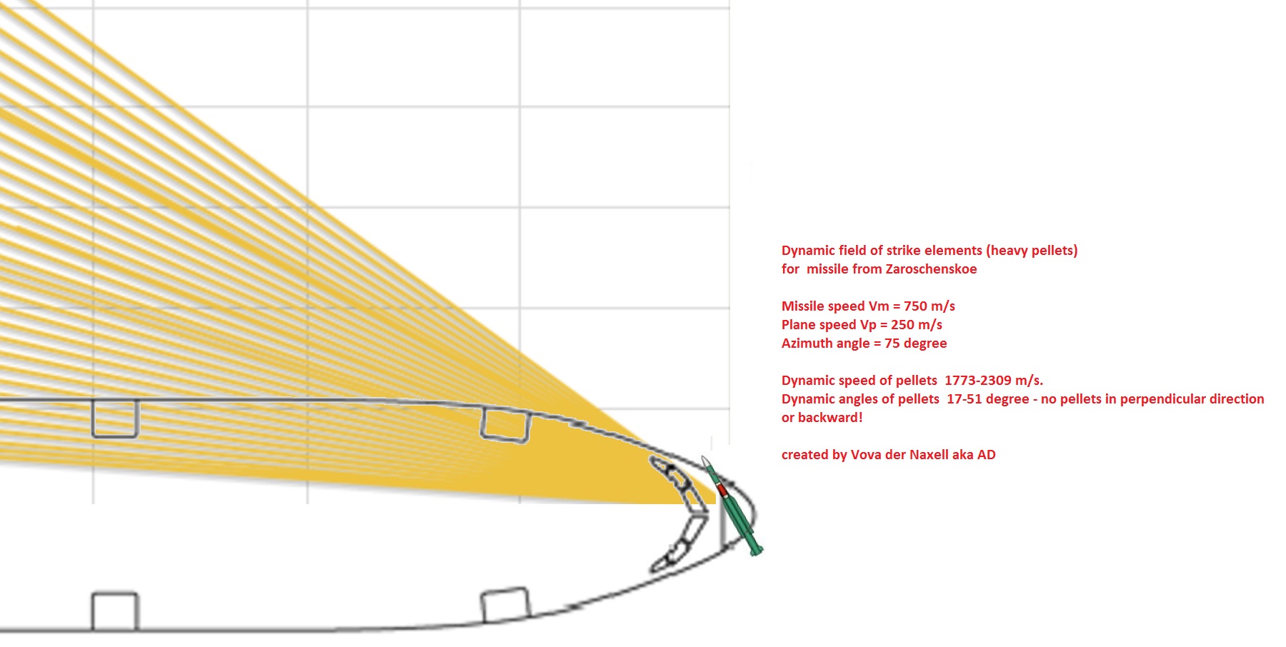
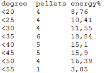
Those two images show different things but angles are the same. The first image in the static realm and only maximum distribution angles while the second image shows some actual dynamic situation, implying all the backwards aimed fragments receive forward thrust resulting in the highest energy in the red zone, which AA claims to has >40% of mass and >50% of kinetic energy of the resulting explosion. This effect might be reached when mounting the heaviest fragments lower in the warhead pointing backwards but perhaps there are other effects as well. It's true that lancet is close to double in mass and energy of what any generic formula would suggest. It's perhaps surprising but not necessarily false unless people can show me field experiments of this actual warhead being detonated at Mach 3. ....
2. Field tests with moving targets dont show how really moving any pellet. Only how many holes you receive on target Name-X which flown on alt, with speed and intercepted with attack angle. Compare it with army wishes and sell to them this warhead.
3. AA give alot false info and >40% mass of fragments with >50% of kinetic energy is part of their incredible lie.
I can explain it but im dont think you really wanna it know. Belivers never need knowledge, their God give them all. But why then you post here? You wanna revert our knowledge into your faith? No way! So AA info im checking with ballistic science and dont find proof on their lie. Do you have proof for their info?
4. Lancet, concentration, perpendicular distribution for most pellets - cannot be used with 9N314 warhead shape. CANNOT. No way for this warhead receive any of these. Or show me how you can receive that results. With science.
5. Do you think science dont work for this actual warhead during field experiment with detonation on Mach 3? Really? You need proof for any changes? Mach 3? Mach 2? Mach 1? How about vector addition? Is it work only on Mach 1? Or TG-24 explosive filling have different detonation speed as function of missile speed? May be warhead shape changes when exploding near B777? Of course, no! Ballistic as science describe any of these changes with tools like Gunrey equation, Taylor angle, Shapiro formula etc. Tools have precision and working range but inside it can describe how actual warhead must work. You must start a picket against Internation Symposium on Ballistic since these guys just eat money without working theory.
So what science using Almaz-Antey? Can you provide proof on their firing tests, modified theory or independent source with same results? No, you cannot. But you can spread out false info from AA as Testament from God.
Last edited: