Where and How could the Wallace Experiment Easily Be Repeated?

Re: accessibility of the Old Bedford River.
There shouldn't be any problem about accessibility of the end points, as these are public road bridges.
The 'midway' marker is not quite so straightforward. There doesn't seem to be any proper footpath along the north-west bank of the river, which is where Wallace put his marker, but the south-east bank should be equally good for the purpose. Google Earth shows a clear path or track on that side of the river, which is probably used by the vehicles of the waterway authority. I wasn't sure whether there is general public access to this track, but I see that it is recommended as part of a circular walk around the wetland nature reserve between the Old and New Bedford Rivers, so there must be some public access. For the experiment there also needs to be access to the water level itself. From photographs the banks can be steep and clogged with vegetation in places, but the Old Bedford River is used by anglers, so there must be at least some access points. There are some images at an angling website here www.welneyanglingclub.co.uk/theoldbedfordriver.htm

As I mentioned a while back, the midpoint is by the pylon crossing, and it can be reached by a dirt track by car.

Re the banks, see the picture below. Note the pylons. The spot on the right bank would be the place to put the marker(s).

upload_2018-5-20_8-36-51-png.32938
 
I've never seen independent evidence that any of his experiments actually happened.

As I mentioned somewhere else, some of Rowbotham's reported experiments strain one's credulity, quite apart from any consideration of the shape of the earth. For example see his account here of an experiment with cannon balls fired upwards (text under fig. 49) http://www.sacred-texts.com/earth/za/za21.htm Note that Rowbotham does not claim explicitly that he performed the experiment himself, but he does imply that it was performed in England, and if not by him, by whom? The experiment as described would be alarmingly dangerous, as any slight misfire or inclination of the cannon (merely embedded in sand) during firing (such as might be caused by its recoil) might send a heavy cannon ball falling on someone's head, or at least through their roof. Moreover, in the first edition of his book Rowbotham mentioned a similar experiment, but more plausibly using an air gun, not a cannon. The details of his later account are too different to refer to the same experiment, but he gives no explanation of the changes. In general I am reluctant to make accusations against the dead, who cannot defend themselves, but it would be reasonable to say that without independent verification none of Rowbotham's accounts should be taken as reliable.
 
Rowbotham:

External Quote:
A strong cast-iron cannon was placed with the muzzle upwards. The barrel was carefully tested with a plumb line, so that its true vertical direction was secured; and the breech of the gun was firmly embedded in sand up to the touch-hole, against which a piece of slow match was placed. The cannon had been loaded with powder and ball, previous to its position being secured. At a given moment the slow match at D was fired, and the operator retired to a shed. The explosion took place, and the ball was discharged in the direction A, B. In thirty seconds the ball fell back to the earth, from B to C; the point of contact, C, was only 8 inches from the gun, A. This experiment has been many times tried, and several times the ball fell back upon the mouth of the cannon; but the greatest deviation was less than 2 feet, and the average time of absence was 28 seconds; from which it is concluded that the earth on which the gun was placed did not move from its position during the 28 seconds the ball was in the atmosphere. Had there been motion in the direction from west to east, and at the rate of 600 miles per hour (the supposed velocity in the latitude of England), the result would have been as shown in fig. 49.

Isn't this logic similar to throwing a ball in a plane, and finding that the ball doesn't move backwards, concluding that the plane isn't moving?


I am glad the operator took cover though.


upload_2018-5-20_21-59-7.png
 
Last edited:
Regarding the height of Wallace's targets:
External Quote:
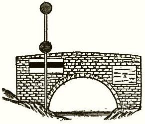
The iron parapet of Welney bridge was thirteen feet three inches above the water of the canal. The Old Bedford bridge, about six miles off, was of brick and somewhat higher. On this bridge I fixed a large sheet of white calico, six feet long and three feet deep, with a thick black band along the centre, the lower edge of which was the same height from the water as the parapet of Welney bridge; so that the centre of it would be as high as the line of sight of the large six-inch telescope I had brought with me. At the centre point, about three miles from each bridge, I fixed up a long pole with two red discs on it, the upper one having its centre the same height above the water as the centre of the black band and of the telescope, while the second disc was four feet lower down.

From 'A Record of Events and Opinions' by Alfred Russel Wallace, p.365
In a nutshell:
  • The lower edge of the black band was 13 feet 3 inches above the water
  • The black band was, at a guess, 12 inches thick
  • The telescope and the centre of the upper disc were at the same height as the centre of the black band
  • Wallace's line of sight was around 13 feet 9 inches above the water
At 6 miles, the 'hump' (sagitta) is mathematically predicted to be 6 feet; wheras Wallace predicted that the middle target would be 5 feet 8 inches above the line of sight (without refraction) and "about five feet" with.

I'm not sure why he has it at 4 inches less. Maybe 'the hump' isn't exactly the same as the distance between the water and the line of sight. Though the only thing that would make a difference to that is the 'tilt' of the two bridges, or the increase in radius due to elevation; but at this distance it's miniscule.

Also, the predicted dip angle between Wallace's telescope and the distant target is 0.0434°.
 
Last edited:
Regarding the height of Wallace's targets:
External Quote:
The iron parapet of Welney bridge was thirteen feet three inches above the water of the canal. The Old Bedford bridge, about six miles off, was of brick and somewhat higher. On this bridge I fixed a large sheet of white calico, six feet long and three feet deep, with a thick black band along the centre, the lower edge of which was the same height from the water as the parapet of Welney bridge; so that the centre of it would be as high as the line of sight of the large six-inch telescope I had brought with me. At the centre point, about three miles from each bridge, I fixed up a long pole with two red discs on it, the upper one having its centre the same height above the water as the centre of the black band and of the telescope, while the second disc was four feet lower down.

From 'A Record of Events and Opinions' by Alfred Russel Wallace, p.365
  • Wallace's line of sight was around 13 feet 9 inches above the water

(I've done some editing here.)

I think I see what your reasoning is, now.

The calico sheet was three feet high, and the center of the black band was probably in the center of the sheet as a whole, but how thick (vertically) was the black stripe? If it were one foot, which seems logical when looking at the sketch, you've added 6 inches to the parapet height to get to the center of the black band. And thus the line of sight from the Welney Bridge would be 13 ft. 9 inches above the water surface.


Something else:

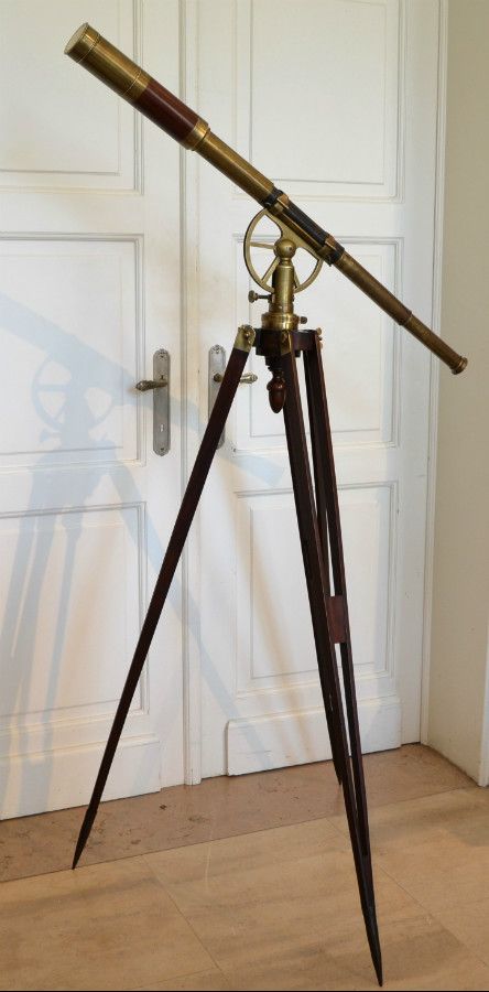
Wallace's six inch telescope was almost certainly a refractor. And most likely an astronomical refractor. Although equatorial mounts did exist at the time, the telescope he was using probably would have looked something like this:

3b8bb55108b88b62743e59fdb1af18e0.jpg


His line of sight would be through the center of the six inch objective, so even allowing for the thickness of the tube, there would be ample space between the tube and the parapet.


Something else to think about:

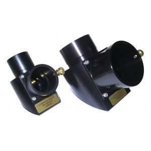
An astronomical refractor shows us an inverted image, unless a "diagonal" is mounted.

2741315c0ba203c165fa2066182d2608.jpg


External Quote:
Refractor... telescopes will produce an image that is upside down when used without a [star] diagonal. When a [star] diagonal is used the image will be corrected right side up, but backwards [mirror imaged] from left to right. It will look like trying to read a sign in a mirror. There are special diagonals called Erect Image Prism diagonals [which use an amici roof prism] that can correct the backwards image for land use.
(Binoculars have an internal correction system: a relay lens in days of yore, and nowadays a Porro prism or roof prism.)

The six inch refractor that Wallace first used evidently presented a right side up image, so it had a diagonal. Whether it had a star diagonal or an erect image prism diagonal... who knows. The latter did exist at the time. It may possibly have had an internal relay lens, if it were designed for land or maritime use.

The point is that the target may have been on the right bank. Impossible to tell because the only letter visible is a capital T.

c9aed9867b8b5c2653602e33dbc4d95b.jpg


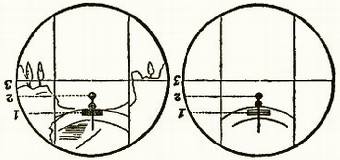
And the sketches of the view through the much smaller inverting refractor don't have enough detail. (The image in that scope must have been quite small.)

425014156f53d8e2b1208ba3fe6049bc.jpg
 
Last edited:
Something I've just noticed: the idea of having an observer and three targets at the same elevation doesn't quite work in showing a modified version of what Wallace showed.

What I was hoping for was this (using Walter Bislin's awesome curvature app):

headoncurve.JPG


But the only way I could get that view was by raising the observer slightly, otherwise it looks like this:

headoncurve2.JPG


Which isn't a million miles from what the flat earth view would look like, for a camera lower than the height of the targets.

I also checked it using my 'mountain range angle calculator', and got the following:

angles.JPG


Which seems to confirm that the order of targets in apparent height, highest to lowest is: near, middle, far (the smaller the angle, the higher in the photo).

When I raise the observer just 4.5 inches, I get this:

angles2.JPG


So for the middle target to be higher than the other two, the viewer needs to be very slightly more elevated than them.

This doesn't impact on the Wallace experiment, as Wallace's telescope was, in effect, the near target. Nor does it change how well the experiment demonstrates the curve. But it is a slight shame that the observer can't be at the exact same height as the targets.
 
Last edited:
I was confused by Wallace's description. I had to reread it.

But before that I thought you'd been confused by where the line of sight through the telescope would be, so it's lucky I deleted that before you caught me.
 
Rowbotham:

External Quote:
A strong cast-iron cannon was placed with the muzzle upwards. The barrel was carefully tested with a plumb line, so that its true vertical direction was secured; and the breech of the gun was firmly embedded in sand up to the touch-hole, against which a piece of slow match was placed. The cannon had been loaded with powder and ball, previous to its position being secured. At a given moment the slow match at D was fired, and the operator retired to a shed. The explosion took place, and the ball was discharged in the direction A, B. In thirty seconds the ball fell back to the earth, from B to C; the point of contact, C, was only 8 inches from the gun, A. This experiment has been many times tried, and several times the ball fell back upon the mouth of the cannon; but the greatest deviation was less than 2 feet, and the average time of absence was 28 seconds; from which it is concluded that the earth on which the gun was placed did not move from its position during the 28 seconds the ball was in the atmosphere. Had there been motion in the direction from west to east, and at the rate of 600 miles per hour (the supposed velocity in the latitude of England), the result would have been as shown in fig. 49.

Isn't this logic similar to throwing a ball in a plane, and finding that the ball doesn't move backwards, concluding that the plane isn't moving?


I am glad the operator took cover though.


View attachment 32950
Rowbotham's 'logic' is unusual. Unlike many flat-earthers, he seems to accept that if an object is projected upwards from a moving base (e.g. a ship in motion) it will continue to move in the direction of the moving base during the upward part of its journey, but as soon as it starts moving downwards, he thinks it will lose the lateral component of its momentum and just fall 'straight down', and therefore land behind its starting point. Rowbotham doesn't explain this loss of lateral momentum, so it is difficult to know what was in his head.

So far as the 'cannonball' experiment is concerned, apart from the unexplained differences between his earlier and later versions, there are several reasons for finding it implausible that it can have been performed in the way he described. Even in Victorian England, repeatedly firing a cannon up into the air would be likely to attract unwanted attention. Where did he get the cannon? Or if he did not do the experiment himself, who did? Were there any witnesses? Without more circumstantial information about how, when, and where the experiment was performed, one is entitled to be sceptical. (His previous account, referring to an air gun, is more plausible. It would be relatively easy to buy an air gun, take it to some remote location, and fire it repeatedly in relative safety.)

As to the physical possibility of the claimed results on a moving earth, I don't think we need doubt that the cannonball would usually fall back approximately to its starting point, as Coriolis-type effects would probably be negligible. But the degree of accuracy claimed by Rowbotham is quite a stretch. Rowbotham claims that in 'many times' the ball never fell back more than 2 feet away, and 'several times' it actually fell back on the mouth of the cannon. This would require an extraordinary degree of precision in the vertical aiming of the cannon, and stability of the cannon during firing, despite being merely 'embedded in sand up to the touch hole'. Given the stated duration of 'flight' (averaging 28 seconds), the ball must have gone at least a few hundred meters up (assuming a muzzle velocity of at least 100 meters per second), so even a very small deviation from vertical would take the landing point more than 2 feet away from the mouth of the cannon.
 
An aside on the idea of 'line of sight'. Wittgenstein, probably the most profound (and difficult) philosopher of the 20th century has this to say:


upload_2018-5-21_13-12-52.png
 
Q. Anyone know the depth of the canal?

I saw on the 2016 flat earth Bedford Level video that they said the canal was 1.2m deep.

I was surprised by that: going by what the boaters were saying, I was expecting it to be shallower.
 
I saw on the 2016 flat earth Bedford Level video that they said the canal was 1.2m deep.

I was surprised by that: going by what the boaters were saying, I was expecting it to be shallower.

Navigable UK canals tend to end up v-shaped, with the full depth only in the middle.
Metabunk 2018-05-21 21-58-59.jpg


I grew up near a canal (Leeds-Liverpool, in Bingley), and they would drain sections of it occasionally. The bottom was soft thick mud, fun to throw rocks into.
 
Sites for repeating the Wallace experiment have mostly focussed on water, for fairly obvious reasons given that it finds its own level.

I wondered what else might be a reasonable substitute for water.

The Trans-Australia Railway has a stretch of line that is perfectly straight for nigh on 300 miles. It is pretty much all on the level (as railways tend to be) with, presumably, a few minor gradients. (Ref: https://en.m.wikipedia.org/wiki/Trans-Australian_Railway)

The weather is almost guaranteed to be perfect, with high visibility and very little water vapour (given it runs through a desert. Edit - although I see some clouds in the image below!). There might be some shimmering effect at ground level but probably not enough to materially affect the results.

There are no bridges or vegetation to obscure the view.

It looks like this (Source:Google Images):
3EB99BCB-143F-4B47-8E5C-82816F409573.jpeg


So that's the where.

As to the how I wouldn't suggest anything drastically different to the suggestions above or indeed the original Bedford experiment. Powerful telescope/camera tracking something like the double container flatbed seen in the picture.

To double check the results and to refute FE claims that it just "went beyond the ability of the optical devices" I would suggest marking the spot at which the train "disappears" and sending up a tethered balloon from that spot until it can be seen by the telescope thereby negating the optical obfuscation.

Just a thought experiment really as it would be a lot of money to show the obvious.

(It might just be my old eyeballs playing up but I think there is a discernible curve to the horizon in that picture)
 
with, presumably, a few minor gradients
Those might be more significant than you think, when you actually come to look along the track. Here's a random 14 miles section:
Metabunk 2018-06-22 08-31-10.jpg

Metabunk 2018-06-22 08-28-55.jpg

(add a Path, then "Show Elevation Profile" on it).

There's a 15-20 foot variation in place over the course of a mile.
 
I'm going here next week (two hour drive, so repeatable if needed). Hopefully I'll have a chance to check out this line. it's about 8 miles.
Metabunk 2018-06-22 08-36-30.jpg
 
Doing the experiment over a water body will suffer due to refraction (unless it is done high enough above the water), and it is almost impossible to find totally level terrain, I guess the best thing is what this guy did:

Source: https://youtu.be/4uwvx7-x98U


He used a theodolite and a 1 mile water hose and three extensions to form communicating vessels that give three level points to compare, on a flat earth the 3 points should align, on a sphere the 3 points will not align as they would be on a curve.

This eliminates the need for a level surface and the problems of refraction.
 
This eliminates the need for a level surface and the problems of refraction.
But does require 1000m of hose, plus a bunch of other equipment. See discussion here:
https://www.metabunk.org/using-a-very-long-water-level-to-measure-earths-curvature.t9710/

Doing the experiment over a water body will suffer due to refraction (unless it is done high enough above the water)

You can minimiuze refraction by choosing the right time of day, preferably an overcast one, and when the temperature of the water is close to the temperature of the air.

The Wallace experiment was specifically designed to avoid the the worse problem of refraction by being several feet above the water surface. The very worst effect happen very close to the surface - like mirages or looming on a road.
 
Those might be more significant than you think, when you actually come to look along the track. Here's a random 14 miles section:
View attachment 33498
View attachment 33497
(add a Path, then "Show Elevation Profile" on it).

There's a 15-20 foot variation in place over the course of a mile.

Good point. However, railway engineers (and trains) hate gradients as they are fighting gravity to climb them and fighting it again whilst braking on the way down.

I have no personal knowledge of that stretch of straight line but I can't help but think that the combination of geomorphology and railway engineers cutting and embanking the track would give you at least part of the 300 miles that was straight and level beyond the available lengths of canals and small lakes.

Still, having no knowledge of what the engineers did to mitigate the landscape I am speculating on something that was only a thought experiment so I'll leave it there.
 
Good point. However, railway engineers (and trains) hate gradients as they are fighting gravity to climb them and fighting it again whilst braking on the way down.

I have no personal knowledge of that stretch of straight line but I can't help but think that the combination of geomorphology and railway engineers cutting and embanking the track would give you at least part of the 300 miles that was straight and level beyond the available lengths of canals and small lakes.
True over the grand scheme of things railways tend to avoid gradients wherever possible, however on the practical side of things they are rarely dead flat. A rise and fall of a few metres over the course of a few miles is as near level as dammit, and of little over all consiquence over several hundred miles of line. This is because the attention to detail needed to detect EVERY minor rise and fall over a long lenght of line that in this case is 300 plus miles long would prove to be overly complex, time consumming and in the end pointless. Then there is the cost of building embankments and cuttings for every rise and fall of a few feet here and there to keep it perfectly level would astromonic, and remember railways are built to often very tight budgets.

Then there is the added problem that any flat earther given a stretch of rail line as any kind of experimental proof would point out the flaws mentioned above and at best dismiss the data as flawed and at worse lay accusations of deceit.

As one of their biggest arguements is water is flat and always finds a level, then a water or liquid surface is needed to present the experiment in a way they can accept.
 
The Trans-Australia Railway has a stretch of line that is perfectly straight for nigh on 300 miles. It is pretty much all on the level (as railways tend to be) with, presumably, a few minor gradients.

The world speed record for a steam engine was famously set on a downhill stretch of line at Stoke Bank, which has a gradient of between 1 in 178 and 1 in 200 for around three miles.

Lickey Incline in Worcestershire is the steepest sustained main-line railway incline in Great Britain, at 1 in 37.7 over two miles.

This doesn't prove that the Trans-Australia Railway isn't level, but it does show that engineers build railway lines with gradients, and so using one for a convincing flat earth experiment isn't going to work.
 
Last edited:
This doesn't prove that the Trans-Australia Railway isn't level, but it does show that engineers build railway lines with gradients.

We know trains can go uphill:-) The problem, as always, is how slight the curvature of the earth is compared to the scale of human perception, and even long railway lines.
 
I suppose it depends on how long a straight and level railway track you would need to make a convincing demonstration of curvature.

There are long and level stretches of railway track.

"The Buenos Aires & Pacific Railway, Argentina (Central Region), is dead straight and almost level for 205 miles." (Guinness Book of Railways)

Also "the Moscow & St Petersburg (Leningrad) Railway is almost straight and level for 400 miles".(Same Ref). Personally I would treat this with caution.

Now in among the "almosts" there should be a stretch that is long and level enough to provide a reasonable demonstration.

Anyhow, enough of railways. I agree that water is the best example as it is answering the question in their terms.

And if the FE community are just going to dismiss any evidence on the grounds of flawed data and deceit then the discussion becomes quasi-religious and there is no point in doing any experiments to negate their fallacious arguments.
 
If the FE community are just going to dismiss any evidence [...] there is no point in doing any experiments to negate their fallacious arguments.

That's pretty much the way it is. One does it for fun, not to try and convince anyone they're mistaken. There's already overwhelming evidence against the flat earth, for those who want to find it. Really, all providing new evidence does is force flat earthers to become ever more creative in devising ad hoc explanations. C'est la vie. :)
 
Hi, just wondered if you had set a date for the 2018 Bedford level experiment. I would like to help if needed and witness this for myself. I have read that the refraction of the light is a factor that needs to be demonstrated also so perhaps the experiment could be conducted at different heights. Refraction would be different at different heights so if the lights shone at different heights were parallel then this removes the refraction argument.
 
Hi, just wondered if you had set a date for the 2018 Bedford level experiment. I would like to help if needed and witness this for myself. I have read that the refraction of the light is a factor that needs to be demonstrated also so perhaps the experiment could be conducted at different heights. Refraction would be different at different heights so if the lights shone at different heights were parallel then this removes the refraction argument.
The experiment needs to be performed in winter, to minimise the effects of refraction and foliage, and preferably close to the original month (March 1870). I am thinking about March 2020, on the 150th anniversary.

All help welcome. I have already contacted a few local people. Next step is to travel there and stake it out.
 
Hi, just wondered if you had set a date for the 2018 Bedford level experiment. I would like to help if needed and witness this for myself.

Hi, that would be great. I've actually relocated to Sweden for the timebeing so am not sure when I'm next in the area. Edby is planning March 2020. I think a drive to generate more interest and participants would be good also - especially from the UK Flat Earth community.

Here's the detailed proposal I made, which I feel would make a good blueprint for anybody interested in doing this, even if I don't:

https://www.metabunk.org/recreating-the-bedford-level-experiment.t9729/

Cheers. :)
 
How about doing this experiment at the University of California at Santa Barbara, looking across the ocean to Santa Barbara 7 miles away, and over more ocean beyond to the hills behind Rincon Point near Carpinteria 21 miles away.
santabarbaratopomap100000scalecroppedwithsightline-png.34463

An experiment just like the Wallace one might not be practical, but I was thinking of something maybe even better. I was thinking of an observer starting on the cliff at USCB about 40 feet above the water, sighting to a board on the beach at Santa Barbara, 10 feet above the water. The board could be maybe 2 feet tall and 8 feet wide, and mounted kind of like a road sign. The observer at UCSB could sight UNDER the board to a laser or light at about 100 feet above the water on the hills behind Rincon Point. The advantage of making the light go under the board, is that then it would hopefully be obvious to the flat earthers that the light had to go from 100 feet, down to UNDER 10 feet, and then back up to 40 feet. And by having the light go visibly under the board, they can't claim that the light close to the surface got "tired" and couldn't make it.

This might also be a good location because even without the board and laser, flat earthers might be able to just go there any time and observe lights on the hills behind rincon point being below the height of the houses on the bluff at Santa Barbara. As Santa Barbara is only about 100 miles from Los Angeles, many flat earthers might be within range to travel there without too great of resources needed. There is a web cam at UCSB that might be useful for identifying clear days before traveling to Santa Barbara. I think the P900 has about 4 inch resolution at 7 miles and about 1 foot resolution at 21 miles. By using lights instead of just passively lit targets, it may be possible to carry out the experiment using cameras with lesser zoom lenses.
 
Ocean versions are problematic because of tides and waves. But very long distances overcome this. The problem then is visibility, with huge variation both in refraction and obscuring
 
How about doing this experiment at the University of California at Santa Barbara, looking across the ocean to Santa Barbara 7 miles away, and over more ocean beyond to the hills behind Rincon Point near Carpinteria 21 miles away.
santabarbaratopomap100000scalecroppedwithsightline-png.34463

An experiment just like the Wallace one might not be practical, but I was thinking of something maybe even better. I was thinking of an observer starting on the cliff at USCB about 40 feet above the water, sighting to a board on the beach at Santa Barbara, 10 feet above the water. The board could be maybe 2 feet tall and 8 feet wide, and mounted kind of like a road sign. The observer at UCSB could sight UNDER the board to a laser or light at about 100 feet above the water on the hills behind Rincon Point. The advantage of making the light go under the board, is that then it would hopefully be obvious to the flat earthers that the light had to go from 100 feet, down to UNDER 10 feet, and then back up to 40 feet. And by having the light go visibly under the board, they can't claim that the light close to the surface got "tired" and couldn't make it.

This might also be a good location because even without the board and laser, flat earthers might be able to just go there any time and observe lights on the hills behind rincon point being below the height of the houses on the bluff at Santa Barbara. As Santa Barbara is only about 100 miles from Los Angeles, many flat earthers might be within range to travel there without too great of resources needed. There is a web cam at UCSB that might be useful for identifying clear days before traveling to Santa Barbara. I think the P900 has about 4 inch resolution at 7 miles and about 1 foot resolution at 21 miles. By using lights instead of just passively lit targets, it may be possible to carry out the experiment using cameras with lesser zoom lenses.

Quite the endorsement for Nikon. I just checked out the specs and saw a few demos from the P900. I think you just cost me $500 :) Which is actually a lot of bang for the buck.
 
I think I estimated the size of an object in a picture by Mick West in another thread and calculated the resolution from that. Four inches at 7 miles is 1.9 arc seconds. The Rayleigh Criterion for a 55mm diameter lens(P900's 357mm focal length divided by 6.5 f number) at 500nm is 1.22*(5x10^-7)/0.055) = 2.3arcsec. So my resolution estimate looks doubtful, though at least in the ballpark. Still, I've got the impression from camera reviews that the P900 had the best resolution available for a comparable price and size until the P1000 came out. And the P1000 appears to cost significantly more. I have found it a little hard to figure out with any accuracy what angular resolution various camera lenses and telescopes are capable of. There are several problems. One is that photographers don't always get the focus perfect on their test images. Another is that atmospheric distortion can vary tremendously. There can also be false detail caused by image sharpening filters applied inside the camera. I can't believe how many long lens reviewers just say things like "this is a very sharp lens" without bothering to quantify it. The whole point of a long lens is to get better resolution, so if you're going to review a long lens, why be vague about the most important performance factor?
 
Is this plan ongoing? I can provide any help needed with the Old Bedford River plan. I live about 15 miles away.

I also have access to some long camera lenses. I have a campsite dedicated to aircraft enthusiasts.
 
Back
Top