Towards A Replicable Physical Model Illustrating Aspects of the Collapse of The WTC Towers on 9/11

Mick West

Administrator
Staff member
UPDATE: Here's the model I eventually arrived at:

Source: https://www.youtube.com/watch?v=flo62pdaIMI


The following thread shows how I got there.


-----------------------------------------------------------------------------------------------

There has been much discussion as to the precise sequence of events during the collapse of the World Trade Center twin towers. The collapse discussion is generally divided into initiation (why it started to collapse) and progression (why it continued to collapse all the way down). Some people suggest it is impossible for the upper part of a structure to "crush" the bottom part of the structure, they build models to try to demonstrate this.

Those models are wrong, because they rely on the supporting columns being crushed as the collapse mechanism. The "official story" is that the floors gave way at their points of attachments to the columns. i.e. the failure begins with floors being stripped away from the columns.

http://www.nist.gov/el/disasterstudies/wtc/faqs_wtctowers.cfm

12. Was there enough gravitational energy present in the WTC towers to cause the collapse of the intact floors below the impact floors? Why weren’t the collapses of WTC 1 and WTC 2 arrested by the intact structure below the floors where columns first began to buckle?

Yes, there was more than enough gravitational load to cause the collapse of the floors below the level of collapse initiation in both WTC towers. The vertical capacity of the connections supporting an intact floor below the level of collapse was adequate to carry the load of 11 additional floors if the load was applied gradually and 6 additional floors if the load was applied suddenly (as was the case). Since the number of floors above the approximate floor of collapse initiation exceeded six in each WTC tower (12 floors in WTC 1 and 29 floors in WTC 2), the floors below the level of collapse initiation were unable to resist the suddenly applied gravitational load from the upper floors of the buildings.
...
This simplified and conservative analysis indicates that the floor connections could have carried only a maximum of about 11 additional floors if the load from these floors were applied statically. Even this number is (conservatively) high, since the load from above the collapsing floor is being applied suddenly. Since the dynamic amplification factor for a suddenly applied load is 2, an intact floor below the level of collapse initiation could not have supported more than six floors. Since the number of floors above the level where the collapse initiated exceeded six for both towers (12 for WTC 1 and 29 for WTC 2), neither tower could have arrested the progression of collapse once collapse initiated. In reality, the highest intact floor was about three (WTC 2) to six (WTC 1) floors below the level of collapse initiation. Thus, more than the 12 to 29 floors reported above actually loaded the intact floor suddenly.
Content from External Source
To illustrate that it's the floors that are failing first, and not the walls, I (and others) have built simple models that show floors being stripped away from walls. Now it's important to remember that these models are illustrative. Because of the square-cube law of scaling it is very difficult to get something truly representative. The intent is firstly to illustrate that an upper portion of a structure can cause the destruction of a much larger lower portion, and secondly to illustrate roughly how this happened in the WTC towers.

My very first attempt some time ago was done with Jenga blocks (regular sized cuboids of wood) and thin strips for the floors. It was moderately successful in illustrating the principle.

But it suffered from numerous problems: very springy floors, overly segmented columns, and a long and fiddly reset time. More significantly it did not simulate the breaking of the seated connections (i.e. where the floors meet the wall) - instead the floors were more jostled out of place. It is also quite small.

So I decided to devote some occasional time to a better model, about which this thread will be a continuing work-in-progress discussion.

I decided to make a free-standing model, with wider "floors" to make it more three dimensional. Each floor section consists of 12" sections of 1x4 dimensioned lumber (0.75" x 3.5" cross section). To simulate the seated connections I stapled a 1" wide strip of laminated paper to the end of the "floor".

[Update: The laminated paper and screws method has been replaced by a vastly better magnets and plates method. The following is left to show how the model evolved]

20160315-132831-yqu1m.jpg

For the columns, I use a 24" (2 foot) tall piece of similar lumber with drywall screws in it at 4,12 and 20" This spacing allows a floor every 8", three floors per column segment, with the column splices being mid-floor.

20160315-133204-z1qz5.jpg

The flexible plastic then sits atop the screw "seats".
20160315-133245-0hfrg.jpg

20160315-133557-sbrtw.jpg

Here's the actual seated connections in the WTC:


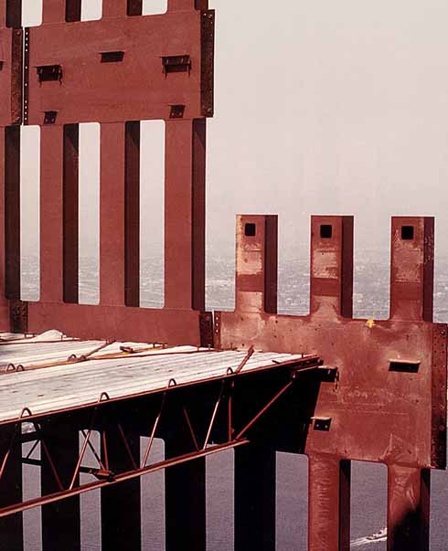
The friction with the screw threads provides some stability, and the bending of the plastic past the screws simulates the failure of the seated connection. The huge advantage of this method of simulating seats is that nothing is broken, and so the model can be easily re-assembled. My first assembly attempt looking like this:

20160315-133918-00tmo.jpg

And my first drop result being this:


There are many obvious problems with this, but I hope to extend it to two floors, and possibly double width with some kind of "core". I will likely have to switch to 2x4s for the columns for stability.

I welcome discussion in this thread regarding the model, what it does or does not illustrate, and suggestions for improvement. But please try to keep any discussion around the model, and not drift off into other 9/11 related topics.

For a detailed overview of the structure of the towers, and the difficulty in modeling them even on a computer, I would recommend reading NIST NCSTAR 1-2 Baseline Structural Performance and Aircraft Impact Damage Analysis of the World Trade Center Towers. The linked version here is "unlocked" so you can copy and paste from it:

https://www.metabunk.org/files/NIST NCStar 1-2 101012_unlocked.pdf
 
Last edited:
Mick,
I think this is excellent. I think that a problem with the collapse is that this model illustrates pancakes... if you will.... and the collapse was definitely not pancakes.... There is also a lot of talk about connection of the floor system to the axial supports failing. That is only PART of the story. The floor slabs themselves would shatter from falling dynamic loads... some would also destroy the connection... for impacts near the connection... at mid span the impacts would likely shatter the slab. We know that there were no intact slabs at the end so the slabs themselves ground each other to smaller and smaller chunks and then to rock size and then sand size. It doesn't take all that much force to crush no stone aggregate lightweight concrete... essentially sand and portland cement to back to sand and cement dust.

The collapse would be like, for example glass sheets dropping and breaking the sheet below and those two broken sheets falling down to a third and then more breakage and finer shards. After 100 floors the glass sheets would be in tiny pieces.

But a model would have strength scaling issues because anything strong and thin would not have the mass to destroy the same in a scaled drop.

Truthers need to understand the dustification of the concrete... and not leave them with the impression that the floor collapse as simple "connection" failures.
 
But a model would have strength scaling issues because anything strong and thin would not have the mass to destroy the same in a scaled drop.

And also it would make a terrible mess in my garage :)

Seriously though, the primary thing to be illustrated here is a floor that fails when other floors fall on it. Other things happen, but like you say, this scale means you can't really model them. One could, for example, make floors out of very thin sheets of plaster, but then air resistance is going to become a major retarding force.
 
So I just made a quick trip to Home Depot. More results to follow after some sawing, screwing, and stapling.
20160315-160517-bx01e.jpg
 
And also it would make a terrible mess in my garage :)

Seriously though, the primary thing to be illustrated here is a floor that fails when other floors fall on it. Other things happen, but of like you say, this scale means you can't really model them. One could, for example, make floors out of very thin sheets of plaster, but then air resistance is going to become a major retarding force.
It's beautiful! You're well on your way to earning your woodworking badge, I think.
What about drywall? It has some (slight) heft to it, so it wouldn't necessarily just flip around and cause a ton of air resistance but it's made of plaster. It comes in a variety of thicknesses, it's cheap, and it might help to explain the whole dust issue with our truther friends. Even if you did one simulation with it to show the progressive crumbling and the rest with your current board floor design, it might help. The only downside is that it's messy...
 
Mick,
I thought that casting very thin sheets of plaster might work... but would the force scale enough to destroy the plaster? You could bake some flakey dough sheets and eat the crumbs!

I am wondering if there is some way to adhere sugar cubes together into a sheet and use them for the floors?

I'll lend you my shop vac!
 
In the interests of replication. I'm making the flexible plastic end pieces by printing out some 1/2" graph paper, laminating it, then cutting it into 3"x1" sections. These are then stapled with 1/2" extending beyond the end of the floor. The staples are put in the same spot using the grid as a guide.

20160315-162759-vpclf.jpg

Alternatively you could use something like playing cards to get a consistent springy connection. I like this though, as it's fairly weak, yet returns to straight very easily.

Laminator plus lamination pouches was about $30 at Walmart
 

Attachments

  • graphpaperhalfinch.pdf
    387.8 KB · Views: 2,193
What about drywall? It has some (slight) heft to it, so it wouldn't necessarily just flip around and cause a ton of air resistance but it's made of plaster. It comes in a variety of thicknesses, it's cheap, and it might help to explain the whole dust issue with our truther friends. Even if you did one simulation with it to show the progressive crumbling and the rest with your current board floor design, it might help. The only downside is that it's messy...

It's also still way too strong, and light. You can't practically drop six sheets of drywall on another and have it break.

However, it's interesting as a thought experiment. One can demonstrate the basic principle with this setup, then invite people to consider "what would happen if the floors were 8' sheets of drywall loaded with bricks instead of the 12" wood boards" - etc.
 
Last edited:
And before it gets brought up, I'm not forgetting "why would the core fall", but I'm not initially trying to demonstrate that. Obviously the outer walls would basically peel outwards as the floors were stripped. But the core is a different thing, and might not be something that can be easily be modeled at this scale. My initial plan is to use 2x4s for the outer walls, and then 2 4x4s for the "core", or something like that.
 
Douglas Fir and Redwood- nothing but the finest for this model :) From Hangtown no less.

I was forced to use Redwood as the Placerville Home Depot's 2x4 in Doug Fir was rather waterlogged and uneven.

Anyway, enough yakking, it's garage time!
 
The core needs to be stacked jenga blocks with similar sticks on the same sort of seats... Real world they were knife joints... welded to the columns.

Also the bracing on the rows of the express elevators... 500-600 and 900-1000 had the bracing attached to the side so has not to limit the shaft clearance.
 
Some thoughts so far:

One function of the floor sections in the actual tower is to hold the columns (and hence the outer skin of the building) vertical. This is not modeled here, but it should be, in order for the "outer walls" (and possible the "core") to fall down as part of the illustration. I need some way of "hooking" the floor connector to the wall. Currently it's just resting on a screw head. So maybe I can bend it down to hook over the screw head - or maybe cut a slot in it.

I'm using 4x4 beams for the "walls", this is obviously not in the slightest bit to scale, and the only reason I'm using them right now is for stability. I should at least be able to switch to 2x4s for one side (the outside) then maybe consider a single 4x4 to be the "core", and do another set of floors on the other side. Alternatively I could make it twice as high.

The "walls" are just balanced one on top of the other. I might be able to make "splice plates" with the laminated paper which would increase stability, but still allow somewhat realistic scaled failure.
 
Last edited:
And before it gets brought up, I'm not forgetting "why would the core fall", but I'm not initially trying to demonstrate that. Obviously the outer walls would basically peel outwards as the floors were stripped. But the core is a different thing, and might not be something that can be easily be modeled at this scale. My initial plan is to use 2x4s for the outer walls, and then 2 4x4s for the "core", or something like that.
Mick I have argued - with little either support OR opposition (OR even interest :() - that the core failure is analogous to the Open Office Space failure. I've used the expression "strip down' or "core strip down" in my posts going back possibly 5 years. Prior to that attention was focussed on the Open Offic Runaway issue and the truth movement claims for "squibs" e.g. Chandlers earlier videos. No interest in "core" which was treated as a secondary aspect.

IMO the mechanisms for both "core" and "OOS" were analogous. "overwhelming weight" -- bypassing the columns -- landing on the horizontal members -- shearing the horizontal member to column connection. So for OOS say "floor joists" and for core say "horizontal beams."

Good work - I will follow progress with interest.
 
http://www.nist.gov/el/disasterstudies/wtc/faqs_wtctowers.cfm

12. Was there enough gravitational energy present in the WTC towers to cause the collapse of the intact floors below the impact floors? Why weren’t the collapses of WTC 1 and WTC 2 arrested by the intact structure below the floors where columns first began to buckle?

Yes, there was more than enough gravitational load to cause the collapse of the floors below the level of collapse initiation in both WTC towers. The vertical capacity of the connections supporting an intact floor below the level of collapse was adequate to carry the load of 11 additional floors if the load was applied gradually and 6 additional floors if the load was applied suddenly (as was the case). Since the number of floors above the approximate floor of collapse initiation exceeded six in each WTC tower (12 floors in WTC 1 and 29 floors in WTC 2), the floors below the level of collapse initiation were unable to resist the suddenly applied gravitational load from the upper floors of the buildings.
...
This simplified and conservative analysis indicates that the floor connections could have carried only a maximum of about 11 additional floors if the load from these floors were applied statically. Even this number is (conservatively) high, since the load from above the collapsing floor is being applied suddenly. Since the dynamic amplification factor for a suddenly applied load is 2, an intact floor below the level of collapse initiation could not have supported more than six floors. Since the number of floors above the level where the collapse initiated exceeded six for both towers (12 for WTC 1 and 29 for WTC 2), neither tower could have arrested the progression of collapse once collapse initiated. In reality, the highest intact floor was about three (WTC 2) to six (WTC 1) floors below the level of collapse initiation. Thus, more than the 12 to 29 floors reported above actually loaded the intact floor suddenly.
Content from External Source

There is a point of engineering pedantry which I don't recall anyone identifying.

The NIST explanation uses "suddenly applied load" which has an amplification factor of 2. That applies to a situation where the load is in contact but held and then released to put its load on the lower support. Zero "distance of fall".

There are three categories of loading viz:
1) Static;
2) suddenly applied; and
3) Impact.

Impact falls or is moving to contact and can have a far higher "amplification factor" than the 2 which occurs with "suddenly".

IMO the real event would have had some dynamic impact component - so the NIST adoption of "suddenly" and "2" is probably another order more conservative than they suggest. Or they saw something that I've missed...:oops:

Doesn't change anything AFAICS so I return viewers to the normal program. [/PedanticEngineerMode]

:rolleyes:
 
There is a point of engineering pedantry which I don't recall anyone identifying.

The NIST explanation uses "suddenly applied load" which has an amplification factor of 2. That applies to a situation where the load is in contact but held and then released to put its load on the lower support. Zero "distance of fall".

Yeah, I though about that as I quoted NIST there. Using "suddenly applied" for a falling load just seems wrong, but as you say it's a conservative application, and it works out, so why confuse people?

However, it might be helpful to delve more into this when addressing the speed of collapse (as opposed to the inevitability). There's a vast difference between a brick being dropped onto a glass table from 1/1000th of an inch above it vs. 10 feet above it. The bare minimum of 6 floors of weight being suddenly applied is going to make the next floor collapse and lead to progressive collapse. But after that you've got a wave of debris going through the floors at an increasing rate of speed, ripping through the last few like a 100mph locomotive through a pile of cardboard boxes.

But back to this model, the loads are clearly not suddenly applied. They are impacts. I trigger the first one with a floor section toppling over. I could perhaps do an initiation condition by (slightly) dropping 6 "floors" on top of the first, but that would be the only sudden application there. After that it's just bam-bam-bam all the way down.
 
Mick I have argued - with little either support OR opposition (OR even interest :() - that the core failure is analogous to the Open Office Space failure. I've used the expression "strip down' or "core strip down" in my posts going back possibly 5 years. Prior to that attention was focussed on the Open Offic Runaway issue and the truth movement claims for "squibs" e.g. Chandlers earlier videos. No interest in "core" which was treated as a secondary aspect.

I'm interested, but I think it's unlikely that I'd be able to incorporate anything like that into this model, given the scale. Possibly I could make a core out of 2 2x4 with very short "floors" in-between, but the scale would make it very hard for them to have sufficient mass to strip connections. Maybe I could add weight.

Anyway, something for later. Tomorrow I'll focus on "hooking" the seats. Maybe using sections of a soda bottle. Luckily I bought lots of extra "floor" wood.
 
Yeah, I though about that as I quoted NIST there. Using "suddenly applied" for a falling load just seems wrong, but as you say it's a conservative application, and it works out, so why confuse people?
Agreed - pragmatic reality for the current purpose.
However, it might be helpful to delve more into this when addressing the speed of collapse (as opposed to the inevitability). There's a vast difference between a brick being dropped onto a glass table from 1/1000th of an inch above it vs. 10 feet above it. The bare minimum of 6 floors of weight being suddenly applied is going to make the next floor collapse and lead to progressive collapse. But after that you've got a wave of debris going through the floors at an increasing rate of speed, ripping through the last few like a 100mph locomotive through a pile of cardboard boxes.
Not a priority interest of mine whether for debunking truther claims OR understanding the engineering dynamics. Because - there are issues of higher priority for debunking AND I doubt we can let alone need do a lot with analysis of speeds. Respectively. And both sub-issues are derails for this thread.
But back to this model, the loads are clearly not suddenly applied. They are impacts. I trigger the first one with a floor section toppling over. I could perhaps do an initiation condition by (slightly) dropping 6 "floors" on top of the first, but that would be the only sudden application there. After that it's just bam-bam-bam all the way down.
Yes - we are definitely into "progression" - the only area where the distinction of "sudden" v "impact" could matter is in the transition from initiation to progression. Also not the topic here and at or above the level of most discussions both on Internet where participants are mostly lay person AND in academic publishing. (I think I'm the only person who has attempted to explain it in a forum setting - and it hasn't raised much interest other than a couple of adverse comments and personal attacks from engineer debunkers who don't like being pushed out of their comfort zones.)
 
Last edited:
I'm interested, but I think it's unlikely that I'd be able to incorporate anything like that into this model, given the scale. Possibly I could make a core out of 2 2x4 with very short "floors" in-between, but the scale would make it very hard for them to have sufficient mass to strip connections. Maybe I could add weight.

Anyway, something for later. Tomorrow I'll focus on "hooking" the seats. Maybe using sections of a soda bottle. Luckily I bought lots of extra "floor" wood.
Understood and agreed. I was posting for information to help understanding - not suggesting modelling at this time.

IMO "hooking" is the next issue of importance to incorporate.

Two of the issues that Jeffrey Orling raises are real but difficult to model and of lower order of importance. These two:
JO said:
and the collapse was definitely not pancakes.... There is also a lot of talk about connection of the floor system to the axial supports failing. That is only PART of the story. The floor slabs themselves would shatter from falling dynamic loads... some would also destroy the connection...
Neither of those damages what you are trying to show with the model and IMNSHO there is zero benefit in trying to incorporate them.
 
Mick,
Probably an unattainable goal to model all the key failures in one model... scaling being the bridge too far. But the other processes can be modeled perhaps.. such as the grinding /breaking, fracturing of the slabs. Truthers will always pull a switch... such the "mysterious" dustification of concrete... A lattice core can teeter and topple when the bracing collapses and the columns in sections are left too tall and spindly.

What about the spacing of your floors? How would that change the model? Would there be a noticeable bunching of them?

Sudden vs impact (dynamic) is the difference between placing a bowling ball on your head and dropping it. So there were really no "sudden" loads which weren't dynamic ones.
 
Last edited:
This reminds me a little bit of the Ronan Point balcony collapse, it is a vertical domino effect because the things that collapse can freely move. This is physically a very trivial problem for which you even do not need an experiment. It becomes extremely non-trivial if you start with a top section that starts as an intact block. I believe I uploaded an image before here that shows the nontrivial problem. ROOSD is what happened but that has no empirical confirmation.
 
IMO "hooking" is the next issue of importance to incorporate.

Agreed, and that is what I shal focus on today. Any suggestions appreciated. Basically I need either a 3" long piece of curved or bent plastic that will deform (and reform) easily. Or something like an actual hook. Maybe some kind of flexible plastic tube (like a large drinking straw) cut into strips.
 
Well that was easy, I just bent the laminated paper down 1/4"

20160316-090129-ktwkv.jpg

This hooks into the treads of the screws, and also pushes against the wall, giving great lateral stability. I can even pick up an entire section of three floors and move it around.

20160316-090218-y615l.jpg
 
instead of screws.... how about short length of tygon tubing inserting into holes in the wood? What about some live load on the floors? If the design LL was 50#/SF and the dead load of the slab was (roughly) 100#/CF x .33 (4") = 33# plus rebar, pans and the trusses... call it 40#/SF... the collapse had more or less equal amounts of dead and live load... (though not every SF had live load on it). Something to consider...
 
instead of screws.... how about short length of tygon tubing inserting into holes in the wood?
The screws work well now, as they provide something for the bent paper to hook into. The hooking part is pretty key , otherwise it's just a "domino tower".

If the design LL was 50#/SF and the dead load of the slab was (roughly) 100#/CF x .33 (4") = 33# plus rebar, pans and the trusses... call it 40#/SF... the collapse had more or less equal amounts of dead and live load... (though not every SF had live load on it). Something to consider...

I don't think a live load would change much. But I could load each floor with some more wood. A big discrepancy here is that all that is falling is the discrete floors, when the real event was a hugely diverse wave of steel and concrete, much finer grained that my model. So adding live load will make it slightly closer to that, but still the difference remains.

It's important though to recognize what the model does not represent well, as well as what it does (if anything :) )
 
The model explain Ronan Point as much as the towers... using lighter floors with LL junk on them would look more like the real thing... more chaotic but still progress downwards
 
I think it is very great that people do these experiments. It would also be great to see some colums breaking in the same rate as the collapsing mass. The important Sauret video shows that the whole top section comes down and a very important observation is that both perimeter and core colums are destroyed implying everything comes down. If the perimeter and core columns fell later than the funneling mass it would be visible from the very beginning. But what we observe is a top section with the same area that falls onto the bottom section.
 
Four suggestions:

1. Measure the maximum capacity of your laminated paper floor seats, and the vertical distance they deflect before they yield. Also, measure the weight of your floors. Adjust seat capacity, or weights, or both, for the relations to be comparable to the real thing (like, capacity = 12x single floor load).

2. Increase floor height, if you can. Perhaps put some leigh-weight mesh on either side of the floors to funnel them such that they don't miss the floor below by too much. I think one of the most difficult scaling problems is that you'd have to scale g inversely proportional to floor height. I have no idea how to increase g in your garage, so the best model would employ original height...

3. Initiate by dropping more or less loose material on the wood floor.

4. The impact in reality is mostly inelastic (concrete fractures, rebar bends, etc), while your wood floors would respond much more elastically. Cover them with something inelastic - a layer of play-doh for example. Or a layer of some loose powder (cement...). The latter gives you lateral ejections.
 
A 12 story progressive collapse. I drop two floors on top.


Unfortunately the iPhone field of view changes when you switch to video, and I forgot, and did not get the top and bottom floors in frame. But still interesting.

I'm using a simple, very weak, knife joint on the 2x4 "outer wall" to give a tad more stability. This led to the bottom three segments of the outer wall (the 2x4s on the right) to remain standing until the wave of rubble reached the bottom, and pushed out the lowest section.

That suggests on possible mechanism for the collapse of the "spire" (the remains of the inner core in the real buildings). The wave of rubble would intuitively cause the most damage at the bottom, when it hits the ground and has to spread sideways more than it did on the way down. Thus, like here, the "spire" would collapse from the bottom.
 
Another interesting observation, one of the two "floors" I dropped then missed all the other floors - i.e. it's ejecta, falling at g. However it did not reach the ground much ahead of the wave of debris. This is very similar to what was observed with the towers.
20160316-122502-fifal.jpg
 
Last edited:
I've attached the .mov file here if you want to scrub through it.

More observations:

  • Floor 11 (the highest visible) starts to fall before the wave hits it because the detaching on floor 12 has pushed out the wall, breaking the connection with 11. This probably would not happen at full scale, as the wall would deform.
  • The same outward spreading at the bottom that pushes out the outer wall also pushes out the "core", but only very slightly, as my core is very heavy and stable.
  • I had created a level base to keep everything as square as possible.
  • It does indeed look somewhat like a "zipper" at high speed.
 

Attachments

  • IMG_7780.MOV
    10.1 MB · Views: 1,044
1. Measure the maximum capacity of your laminated paper floor seats, and the vertical distance they deflect before they yield. Also, measure the weight of your floors. Adjust seat capacity, or weights, or both, for the relations to be comparable to the real thing (like, capacity = 12x single floor load).

A quick test showed the floor to fail at 9x. However the hooked connectors are getting progressively weaker with each usage. Plus here I'd removed the upper floor, making the whole structure weaker. Hence I think in the previous tests, it was probably closer to 12x.
 
Last edited:
Mick,
This is brilliant! You can see the same core "spire" behavior in your slender columns... some topple away... some break and drop from joint failure. WOW just WOW,

Wait til Jon Cole sees this! hahahahha...

once you add some random live loads (thin the floors)... change to portrait mode... you'll have a damn good model resembling real world.

Of course the model can be a miniature version of real world.... this can't be scaled... but it does make some excellent points.
 
Last edited:
Back
Top