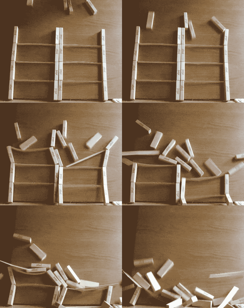
UPDATE: Here's the model I eventually arrived at:
Source: https://www.youtube.com/watch?v=flo62pdaIMI
The following thread shows how I got there.
-----------------------------------------------------------------------------------------------
There has been much discussion as to the precise sequence of events during the collapse of the World Trade Center twin towers. The collapse discussion is generally divided into initiation (why it started to collapse) and progression (why it continued to collapse all the way down). Some people suggest it is impossible for the upper part of a structure to "crush" the bottom part of the structure, they build models to try to demonstrate this.
Those models are wrong, because they rely on the supporting columns being crushed as the collapse mechanism. The "official story" is that the floors gave way at their points of attachments to the columns. i.e. the failure begins with floors being stripped away from the columns.
http://www.nist.gov/el/disasterstudies/wtc/faqs_wtctowers.cfm
My very first attempt some time ago was done with Jenga blocks (regular sized cuboids of wood) and thin strips for the floors. It was moderately successful in illustrating the principle.

But it suffered from numerous problems: very springy floors, overly segmented columns, and a long and fiddly reset time. More significantly it did not simulate the breaking of the seated connections (i.e. where the floors meet the wall) - instead the floors were more jostled out of place. It is also quite small.
So I decided to devote some occasional time to a better model, about which this thread will be a continuing work-in-progress discussion.
I decided to make a free-standing model, with wider "floors" to make it more three dimensional. Each floor section consists of 12" sections of 1x4 dimensioned lumber (0.75" x 3.5" cross section). To simulate the seated connections I stapled a 1" wide strip of laminated paper to the end of the "floor".
[Update: The laminated paper and screws method has been replaced by a vastly better magnets and plates method. The following is left to show how the model evolved]

For the columns, I use a 24" (2 foot) tall piece of similar lumber with drywall screws in it at 4,12 and 20" This spacing allows a floor every 8", three floors per column segment, with the column splices being mid-floor.

The flexible plastic then sits atop the screw "seats".


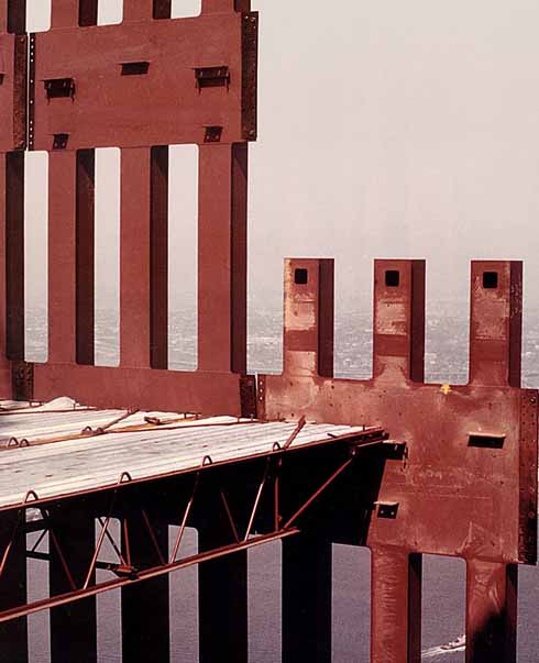
Here's the actual seated connections in the WTC:

The friction with the screw threads provides some stability, and the bending of the plastic past the screws simulates the failure of the seated connection. The huge advantage of this method of simulating seats is that nothing is broken, and so the model can be easily re-assembled. My first assembly attempt looking like this:

And my first drop result being this:
There are many obvious problems with this, but I hope to extend it to two floors, and possibly double width with some kind of "core". I will likely have to switch to 2x4s for the columns for stability.
I welcome discussion in this thread regarding the model, what it does or does not illustrate, and suggestions for improvement. But please try to keep any discussion around the model, and not drift off into other 9/11 related topics.
For a detailed overview of the structure of the towers, and the difficulty in modeling them even on a computer, I would recommend reading NIST NCSTAR 1-2 Baseline Structural Performance and Aircraft Impact Damage Analysis of the World Trade Center Towers. The linked version here is "unlocked" so you can copy and paste from it:
https://www.metabunk.org/files/NIST NCStar 1-2 101012_unlocked.pdf
Source: https://www.youtube.com/watch?v=flo62pdaIMI
The following thread shows how I got there.
-----------------------------------------------------------------------------------------------
There has been much discussion as to the precise sequence of events during the collapse of the World Trade Center twin towers. The collapse discussion is generally divided into initiation (why it started to collapse) and progression (why it continued to collapse all the way down). Some people suggest it is impossible for the upper part of a structure to "crush" the bottom part of the structure, they build models to try to demonstrate this.
Those models are wrong, because they rely on the supporting columns being crushed as the collapse mechanism. The "official story" is that the floors gave way at their points of attachments to the columns. i.e. the failure begins with floors being stripped away from the columns.
http://www.nist.gov/el/disasterstudies/wtc/faqs_wtctowers.cfm
To illustrate that it's the floors that are failing first, and not the walls, I (and others) have built simple models that show floors being stripped away from walls. Now it's important to remember that these models are illustrative. Because of the square-cube law of scaling it is very difficult to get something truly representative. The intent is firstly to illustrate that an upper portion of a structure can cause the destruction of a much larger lower portion, and secondly to illustrate roughly how this happened in the WTC towers.
12. Was there enough gravitational energy present in the WTC towers to cause the collapse of the intact floors below the impact floors? Why weren’t the collapses of WTC 1 and WTC 2 arrested by the intact structure below the floors where columns first began to buckle?
Yes, there was more than enough gravitational load to cause the collapse of the floors below the level of collapse initiation in both WTC towers. The vertical capacity of the connections supporting an intact floor below the level of collapse was adequate to carry the load of 11 additional floors if the load was applied gradually and 6 additional floors if the load was applied suddenly (as was the case). Since the number of floors above the approximate floor of collapse initiation exceeded six in each WTC tower (12 floors in WTC 1 and 29 floors in WTC 2), the floors below the level of collapse initiation were unable to resist the suddenly applied gravitational load from the upper floors of the buildings.
...
This simplified and conservative analysis indicates that the floor connections could have carried only a maximum of about 11 additional floors if the load from these floors were applied statically. Even this number is (conservatively) high, since the load from above the collapsing floor is being applied suddenly. Since the dynamic amplification factor for a suddenly applied load is 2, an intact floor below the level of collapse initiation could not have supported more than six floors. Since the number of floors above the level where the collapse initiated exceeded six for both towers (12 for WTC 1 and 29 for WTC 2), neither tower could have arrested the progression of collapse once collapse initiated. In reality, the highest intact floor was about three (WTC 2) to six (WTC 1) floors below the level of collapse initiation. Thus, more than the 12 to 29 floors reported above actually loaded the intact floor suddenly.
My very first attempt some time ago was done with Jenga blocks (regular sized cuboids of wood) and thin strips for the floors. It was moderately successful in illustrating the principle.

But it suffered from numerous problems: very springy floors, overly segmented columns, and a long and fiddly reset time. More significantly it did not simulate the breaking of the seated connections (i.e. where the floors meet the wall) - instead the floors were more jostled out of place. It is also quite small.
So I decided to devote some occasional time to a better model, about which this thread will be a continuing work-in-progress discussion.
I decided to make a free-standing model, with wider "floors" to make it more three dimensional. Each floor section consists of 12" sections of 1x4 dimensioned lumber (0.75" x 3.5" cross section). To simulate the seated connections I stapled a 1" wide strip of laminated paper to the end of the "floor".
[Update: The laminated paper and screws method has been replaced by a vastly better magnets and plates method. The following is left to show how the model evolved]
For the columns, I use a 24" (2 foot) tall piece of similar lumber with drywall screws in it at 4,12 and 20" This spacing allows a floor every 8", three floors per column segment, with the column splices being mid-floor.
The flexible plastic then sits atop the screw "seats".
Here's the actual seated connections in the WTC:

The friction with the screw threads provides some stability, and the bending of the plastic past the screws simulates the failure of the seated connection. The huge advantage of this method of simulating seats is that nothing is broken, and so the model can be easily re-assembled. My first assembly attempt looking like this:
And my first drop result being this:
There are many obvious problems with this, but I hope to extend it to two floors, and possibly double width with some kind of "core". I will likely have to switch to 2x4s for the columns for stability.
I welcome discussion in this thread regarding the model, what it does or does not illustrate, and suggestions for improvement. But please try to keep any discussion around the model, and not drift off into other 9/11 related topics.
For a detailed overview of the structure of the towers, and the difficulty in modeling them even on a computer, I would recommend reading NIST NCSTAR 1-2 Baseline Structural Performance and Aircraft Impact Damage Analysis of the World Trade Center Towers. The linked version here is "unlocked" so you can copy and paste from it:
https://www.metabunk.org/files/NIST NCStar 1-2 101012_unlocked.pdf
Last edited:
