RobertBillyBob
Senior Member.
There are some great posts on Metabunk explaining how the Raytheon MTS systems work (OSD, FOVs, tracking modes and other settings etc.) but they are scattered through different threads. It's not always easy to search for them when you are having a doubt or a question.
I thought it would be useful to have a dedicated thread to gather existing knowledge and discuss the technical side of the systems (mainly MTS-B) without tying the discussion to any particular case.
I'll start things up with what I found about the mts-b FOVs, it's kind of reversed engineered from the video that where released :
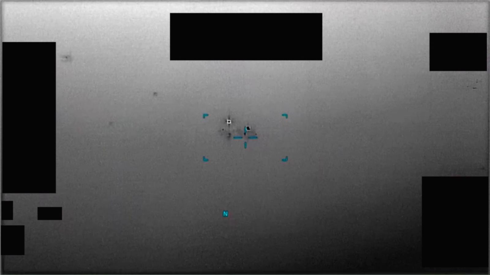
The corners ("┘","┌","┐","└") on the OSD show the borders of the next level of zoom. This way the operator knows if the object will stay in frame when they zoom in.
Knowing the relative FOVs of each zoom level allows us to guess which zoom level we are currently at in redacted videos by looking at the position of those corners.
For example we know this frame uses the medium-narrow FOV because going from medium-narrow to narrow is the only time the FOV shrink this much in one step :
Using the datasheet, PR060 and PR091 I made "rulers" (see attached files) for IR and FMV modes. You can overlay them to different videos to get the current FOV.
Some remarks from studying a few videos :
I thought it would be useful to have a dedicated thread to gather existing knowledge and discuss the technical side of the systems (mainly MTS-B) without tying the discussion to any particular case.
I'll start things up with what I found about the mts-b FOVs, it's kind of reversed engineered from the video that where released :
The corners ("┘","┌","┐","└") on the OSD show the borders of the next level of zoom. This way the operator knows if the object will stay in frame when they zoom in.
Knowing the relative FOVs of each zoom level allows us to guess which zoom level we are currently at in redacted videos by looking at the position of those corners.
For example we know this frame uses the medium-narrow FOV because going from medium-narrow to narrow is the only time the FOV shrink this much in one step :
Using the datasheet, PR060 and PR091 I made "rulers" (see attached files) for IR and FMV modes. You can overlay them to different videos to get the current FOV.
Some remarks from studying a few videos :
- IR and FMV modes don't have exactly the same corner position, so the corresponding FOVs are likely slightly different.
- We don't have many FMV videos so we don't have examples for all zoom levels in FMV. My FMV ruler uses some assumptions that way be wrong.
- "Narrow","Medium" and "Wide" share the same corner position (at least in IR). If the zoom level changes in the video you can deduce the current zoom level relative to the others, but if there is no zoom change I'm not sure we can distinguish them.
- If there is no visible corner it likely means you're at max zoom level (ultra narrow + x4 digital zoom)