smfrnz
New Member
So hopefully now we can expect more footage being that the area isn't under that mandatory order anymore?Well, there was a mandatory evacuation order, and the spillway viewpoint below the dam is kind of in the danger area.

So hopefully now we can expect more footage being that the area isn't under that mandatory order anymore?Well, there was a mandatory evacuation order, and the spillway viewpoint below the dam is kind of in the danger area.
This area is an at risk/high risk section that needs to be addressed IMO.
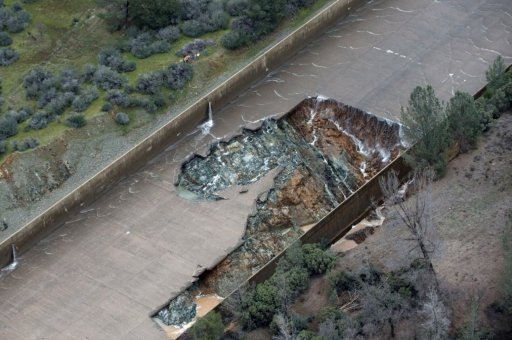
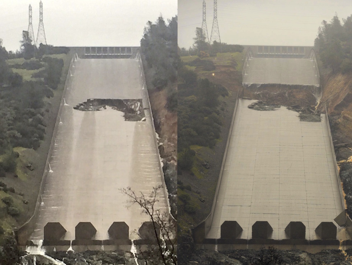
The parking lot spillway is a minimal, narrow, concrete wall. I suspect it isn't very deep at all.
Brad, I haven't tried to look for all the details in all the photos you mention, but I do think your idea regarding the layout of the concrete structure of the emergency spillway makes good sense. It seems like a good way to explain what seems to be an ever-decreasing height of the overflow structure from right to left (using your definition of right and left), and it also would seem to answer the question regarding the apparent inconsistency in design, when comparing the weir to that very small wall to the left. It would also likely explain why the designers thought it was okay to just end the weir so abruptly, apparently not being concerned about erosion at that end point.Ever since I first saw a close up picture of the emergency spillway, I have been trying to understand what was going on there. Even before the water started going over it, there was nothing there to absorb the force of the water and stop erosion of material up close to the weir. After following this site for a couple of days, I MAY have an answer thanks to all the things that have been posted here.
When they were building the dam they knew they needed a weir to act as the emergency spillway, they knew that the top of it needed to be at 901, and they knew they needed it to the left (looking upstream) of the main spillway. They needed to put it on competent (solid) rock, and they needed a shelf of competent rock out in front of it, say 100 feet wide to stop the upstream erosion. You can see this in the drawing on reply #354. Those little hash marks at the bottom of the cross-section of the weir are a standard symbol for rock.
So they started removing the soil and loose rock to the left of the main spillway until they had a bench 150 feet wide. They removed the rock with rippers (post #428) because with a ripper you can create a level surface, and you know when all the loose or weathered rock has been removed. As they moved further away from the main spillway the competent rock was higher, so the rock bench kept moving up. This is why the weir gets shorter as it moves to the left.
The reason the competent rock gets higher is because there was more soil over the rock, as can be seen in post #450. The Rock Whisperer in post #409 explains that the rock in the area breaks down due to its exposure to rain an air, so the competent rock is generally at some constant depth under the surface of the soil. As the hill get higher, the solid rock is located at a higher elevation.
As Mr. Neubauer states in post #374 the designed weir on solid rock will not go anywhere.
The light bulb really went on for me when I saw the second picture in Post #484. You can see what looks like a solid rock wall that is perfectly flat on top of it. It appears to be a solid block of rock. On top of this big slab of rock is a very small wall, the top of which is a 901 feet. This wall is also shown in the cross-sections on Post #354. So in this area they found competent rock at an elevation slightly lower than 901 an needed this very low wall to keep the top of the emergency spillway consistant. Past this area (the parking lot) the hill goes on up (as can be seen in the backgound of the second picture in Post #484) so they didn't need to extend the emergency spillway any further.
So at the end of construction they had an emergency spillway extending from the main spillway all the way to the hillside, AND there was a shelf of strong competent (solid) rock extending out in front of it for 100 feet (or so.)
The problem is that as the Rock Whisperer pointed out, this rock can weather greatly when exposed to the elements. So over the next 60 years the rock broke down and when the emergency spillway was used for the first time a couple of days ago, the "solid" rock started to erode. It was "solid" 60 years ago when they built the dam and everybody thought it was still good up until a couple of days ago. I sure they were quite surprised when their "solid" rock started to wash away.
I would expect that the work they are doing now is just a patch. When the danger of flooding is over I would expect that they will build a substantial structure in front of the entire length of the emergency spillway to make up for the missing "solid" rock.
Interesting document. I also ran across some interesting thinga about the construction of the dam/spillway/emergency spillway:Um... guys... the spillway used two different kinds of concrete.
https://archive.org/details/zh9californiastatew2003calirich
Page 93
Page100 of https://ia800302.us.archive.org/3/items/zh9californiastatew2003calirich/zh9californiastatew2003calirich_bw.pdf said:The flood control outlet radial gates are operated by
electric-motor-powered cable-drum hoists located on
the hoist deck. The gates may be operated locally or
remotely from the Oroville Area Control Center.
Normal power for hoist operation is supplied through
a buried distribution line from Edward Hyatt station
service power system. Standby power is available locally
in the form of a 55-kW generator operated by a
liquid-propane-gas-fueled engine. Normal power supply
is sufficient to operate all gates simultaneously.
Page100 of https://ia800302.us.archive.org/3/items/zh9californiastatew2003calirich/zh9californiastatew2003calirich_bw.pdf said:Emergency Spillway. The grout curtain was continued
under the left reach of the emergency weir
near the upstream face, and formed drains are used
under the downstream half. The crest of the emergency
weir to the right, which is only 1 foot above the
excavated channel, is keyed 2 feet into the foundation.
Both weir sections were checked for overturning and
shear friction safety factor and found to be satisfactory.

If you download the b&w PDF ( https://ia800302.us.archive.org/3/i...lirich/zh9californiastatew2003calirich_bw.pdf ), Page 100 says:
Later on the page it says:
If you want to read about how the dam was built and the nitty gritty of the technical details of the design considerations, start at page 63 of the aforementioned PDF.
Aaron Z
Um... guys... the spillway used two different kinds of concrete.
https://archive.org/details/zh9californiastatew2003calirich
Page 93.
Below 865 feet has a higher PSI strength.
Sorry, I never got back to adding a explication to the beginning of my post, those were just some other interesting things I saw in that document that are related to some of the myths that people have been spreading about the spillways (such as that the emergency spillway is built on dirt rather than being set in rock and that if they lose the power lines across the emergency spillway they will lose power to control the gates)I'm puzzled. Your quotes aren't relevant to the type of concrete in the spillway.
Continued migration uphill would likely be slow but steady for regions of the floor resting on fill - although the change in slope as it moves upward will decrease the energy available for such work. Probably as the trough approaches the gates it is increasingly tied to bedrock
The reinforced invert slab has
a minimum thickness of IS inches and is anchored to
the rock with grouted anchor bars and provided with
a system of underdrains.
Okay, this is a followup post to my earlier remarks on under-slab drainage, and these photos from one of Mick's earlier posts illustrate what I'm thinking about this time around.
Okay, this is a followup post to my earlier remarks on under-slab drainage, and these photos from one of Mick's earlier posts illustrate what I'm thinking about this time around.
If the water is "piled up" as high as those wall drains, and let's assume that's a height of 10 feet above the slab,
Actually, each section is anchored to bedrock and is resting on 5-6 feet of fill. So fill probably drops out at the fracture point, and the anchors into rock continue to provide support. Don't know if the anchors can support the slabs without the fill.
(page 96 of recently linked document has an illustration of the chute which seems to mention fill)
")
If you look at the WP photo you can see that complete floor panels fell/were carried away over deep fill while chunks and pieces were broken away over the bedrock (where the anchoring, whatever it is, was effective). Perhaps the initial failure was caused by hydraulic pressure from saturated soil as was suggested above by EricL. The soil above the failure should be able to drain more effectively now though
Here, we see possible evidence of a different problem - water pressure. If the water is "piled up" as high as those wall drains, and let's assume that's a height of 10 feet above the slab, then the pressure of the water beneath adjacent parts of the slab is that same 10 feet plus the thickness of the slab.
There is one bit of evidence in your photos. Look on the left photo, at the right sidewall just below the bottom of the break. Is that a drain which is spitting a lot more water into the chute than the other drains? That supports the theory that those are drains from the immediate area, rather than some silly place like 200 feet further uphill.
i found this about another spillway that failed. i havent read the whole thing, but looks like there is a diagram that maybe you guys can decipher (as i dotn know what i'm looking at really)That supports the theory that those are drains from the immediate area, rather than some silly place like 200 feet further uphill
Let's drop the rose-colored glasses for a moment.
Look at this CDEC dam data right now:
http://cdec.water.ca.gov/cgi-progs/queryF?s=ORO
They're running at 99,000 cu ft/s outflow. They've been doing this all day. They're telling the public they're lowering the reservoir level by 50 feet. But the level, right now, is only 4 feet from the lip of the emergency spillway and it has been climbing all day! Something isn't right with all this rosy logic.
[Mod: misleading post removed]
Inverted (to avoid takedown, apparently) Satelllite video feed apparently from KCRA helicopter today. At 18 minutes:
Source: https://www.youtube.com/watch?v=ahOEdiYj8z8#t=18m0s
Inverted (to avoid takedown, apparently) Satelllite video feed apparently from KCRA helicopter today. At 18 minutes:
Source: https://www.youtube.com/watch?v=ahOEdiYj8z8#t=18m0s
shows bulldozers building trenches to river upstream from main spillway back towards dam. It would seem to be a stretch that they're trying to dam backflow from that point.
There are dropouts in the video, but watch the zoom out shot at 20 minutes. If the main spillway fails farther back, there is a valley in the mountain parallel to the damn. Where would that water go, and are they prepping for it?
To some of the earlier comments about the quantity of equipment in play and the methods being used to deploy materials - most of this video is worth watching as it spends a generous amount of time on different areas of the works in progress.
Various types of spillways were studied and mod-
eled to arrive at the final structure. The original de-
sign consisted of a control structure with radial gates
to pass the total spillway design flood. A short con-
crete apron was to extend downstream from the con-
trol structure, and then the flows were to be turned
loose down the hillside in an excavated pilot channel.
As the spillway would operate on the average of every
other year, this plan was determined to be unaccepta-
ble based on the large quantities of debris that would
be washed into the Feather River and could ultimate-
ly affect power operations.
...
[However]
No concrete lining is used in the plunge pool [at the base of the lined spillway]
as rock of adequate quality exists near the ground
surface.
Emergency Spillway. The grout curtain was con-
tinued under the left [viewed from the upstream side]
reach of the emergency weir near the upstream face,
and formed drains are used under the downstream half.
The crest of the emergency weir to the right, which is
only 1 foot above the excavated channel, is keyed 2 feet
into the foundation. Both weir sections were checked for
overturning and shear friction safety factor and found
to be satisfactory.

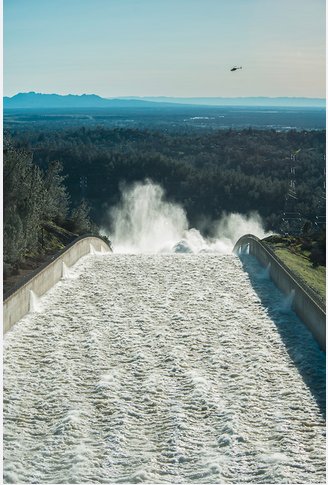
Are you suggesting they should use more equipment than is necessary in order to reassure people?Woo Hoo, 2 backhoes, 3 cement trucks and 1 cement pumper.
I'm pretty sure the 180,000 people evacuated down below the aux-spillway are safely reassured that this is enough.
If you look at the mirrored video at 14:41 (screenshot below), they have two more pumper trucks sitting where the spillway joins the emergency spillway (not sure what they have planned, but they are available if they need them), at that point, there are at least 4 trucks on site (2 unloading into the active pumper, one coming in and one going out). This screenshot also shows another reason they probably dont have more trucks coming in. Those off road dumptrucks take up most of a "2 lane" road, so they can only run so many at a time as one truck (either in our out) needs to pull off to the side to let the trucks going the other way pass:Woo Hoo, 2 backhoes, 3 cement trucks and 1 cement pumper.
I'm pretty sure the 180,000 people evacuated down below the aux-spillway are safely reassured that this is enough.


Whoever shot the video owns the copyright for the video and can ask Youtube to take it down.why would these videos be subject to a take down?
Surely there's a public right to know what is occurring at a publicly owned facility that could threaten the safety of....the public?