You are using an out of date browser. It may not display this or other websites correctly.
You should upgrade or use an alternative browser.
You should upgrade or use an alternative browser.
Does Damage to MH17 indicate or exclude a Particular Buk Launch Location?
- Thread starter william wiley
- Start date
Interesting, I was translating the frag vector and then just drawing the spread around this new vector. I knew this wasn't quite right, as this was more of a rotation than a translation. So I'm fixing it. Here the left side of the image shows the correct (significantly narrower) cone, and the distribution of velocities (faster at the front (top of the image, in the direction of motion of the missile. The right side shows the incorrect spread, wider with even velocities.
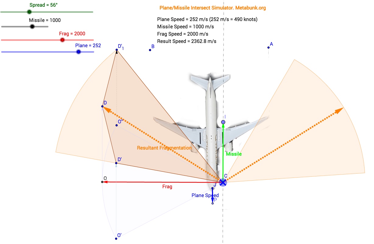
(I realize this is opaque to most people, sorry)
Here's the fixed version:
http://tube.geogebra.org/student/m1340379

(I realize this is opaque to most people, sorry)
Here's the fixed version:
http://tube.geogebra.org/student/m1340379
Last edited:
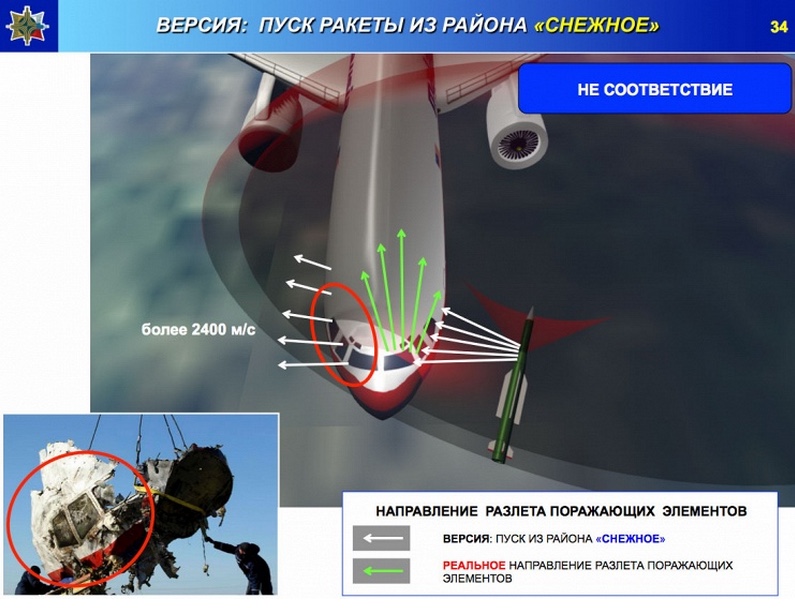
Interesting to compare the resultant vector distribution with what the Russians presented:

Theirs seems to suggest that the sideways fragments are traveling the fastest. If they all start out the same then this is wrong. Those segment are propelled backwards relative to missile, so they end up going slower (as seem in mine).
Imagine you are in a car at 90 mph throwing rocks at street signs. If you throw forward, your 30 mph throw is combined with the speed of the car, and it hits the sign at 120 mph. You can throw backwards and still hit it, but you'll only hit it at 60 mph. Same kind of thing here.
So it looks to me like their diagram is kind of from the point of view of the missile and not the plane. So either I'm missing something, or that's crazy wrong.
Last edited:
Rob
Member
Mick, first of all THANK YOU for that awesome missile animation tool !
That is going to be extremely helpful in verifying or debunking Almaz Antey's claims.
Also, in that post # 44 you hit the main problem with Almaz Antey's analysis :
For a symmetric warhead blasting fragments 90 deg (static) sideways, the main concentration of fragments should end up in the direction of the yellow dotted lines. At the very least 50% the fragments should end up above and 50% should end up below the dotted yellow line.
Almaz Antey's purple (main blast) wedges are clearly below the dotted line ONLY, and that is physically impossible unless the warhead is heavily asymmetric (blasting mostly backward) OR they made a mistake in their velocity vector additions.
That is the MAIN mistake they make, and it seriously affects their conclusions.
That's why I gave you a "winner" vote for that.
But first we should fill in the variables with some more accuracy, and determine the angles for a launch from Zaroshens'ke and from Snizhne. I found that Zaroshens'ke (Russian Defense Ministry launch site) is at 85 deg right of the plane,
and the launch field south of Snizhne is at 19 deg right of the plane.
I'll post a map about that as soon as I have half an hour.
Question : Could you possibly display the angle that the missile is pointing at ?
That makes it easier to set incoming missile angle accurately.
Last edited:
william wiley
Member
I don't think they explicitly said that. Why do you see that suggestion there?Interesting to compare the resultant vector distribution with what the Russians presented:
View attachment 13373
Theirs seems to suggest that the sideways fragments are traveling the fastest.
In the diagram.I don't think they explicitly said that. Why do you see that suggestion there?
Question : Could you possibly display the angle that the missile is pointing at ?
That makes it easier to set incoming missile angle accurately.
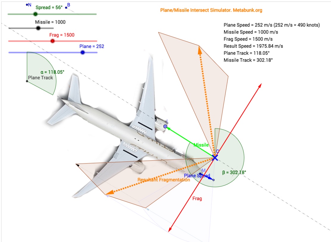
Done, I put the plane and the missile oriented with the page north-up and added angle displays, plane set to 118 based on FR24 last heading
http://tube.geogebra.org/student/m1340901
David Coulter
Senior Member.
General question for Mick - can we play around with your model or will that mess up what you have done?
Rob
Member
Here is a GoogleEarth map with the relevant locations and angles indicated :

MH17 path is the white line, with MH17 heading and point of impact (last Flight Data Recorder location) from the Dutch Safety Board report :
http://www.onderzoeksraad.nl/upload...3acad0ceprem-rapport-mh-17-en-interactief.pdf
Page 20 mentions the heading (115°) :
The Zaroshens'ke location is taken from the picture of the field from the Russian Defense Ministry, which match with GPS coordinates 47.983517°N, 38.452387°E.
The Snizhne launch location is taken from the Telegraph/ukraine@war/US/Bellingcat field south of Snizhne, which match with GPS coordinates 47.974597°N, 38.760164°E.
Given these locations and angles, as seen from the cockpit of MH17 at last FDR point,
the Zaroshens'ke location was 85° (to the right) at 17 km distance,
and the Snizhne location was 19° (to the right) at 24.3 km distance.
Please correct me if I made a mistake somewhere.
MH17 path is the white line, with MH17 heading and point of impact (last Flight Data Recorder location) from the Dutch Safety Board report :
http://www.onderzoeksraad.nl/upload...3acad0ceprem-rapport-mh-17-en-interactief.pdf
Page 20 mentions the heading (115°) :
Page 21 has a map with the last FDR point indicated, which match with GPS coordinates 48.127997°N, 38.526789°E.External Quote:The data on the Flight Data Recorder indicated that the aircraft was flying at FL330, on a constant displayed heading of 115° and at a constant speed of 293 kts computed airspeed (groundspeed 494 kts, equals 915 kilometers per hour
The Zaroshens'ke location is taken from the picture of the field from the Russian Defense Ministry, which match with GPS coordinates 47.983517°N, 38.452387°E.
The Snizhne launch location is taken from the Telegraph/ukraine@war/US/Bellingcat field south of Snizhne, which match with GPS coordinates 47.974597°N, 38.760164°E.
Given these locations and angles, as seen from the cockpit of MH17 at last FDR point,
the Zaroshens'ke location was 85° (to the right) at 17 km distance,
and the Snizhne location was 19° (to the right) at 24.3 km distance.
Please correct me if I made a mistake somewhere.
Last edited:
Herman Aven
Member
Correct me if I am wrong but from what I have read it appears that the missile's trajectory in the horizontal plane is not going to be straight. The missile uses a proportional navigation system which would put the missile onto a straight line intercept IF both the missile and the plane are travelling at constant speeds. In the presentation we are told that MH17 was maintaining a constant speed, but the missile started at 0 and went supersonic. This means that the path of the missile is going to curve slightly as it adjusts its trajectory in order to maintain a constant angle of line of sight to the target as it accelerates.
But wasn't the whole point of the BUK that it had all those radar and targeting systems? That would mean the BUK software very likely could calculate, as default, the shortest route to estimated point of impact using the vector, target speed and direction but of course also knowing its own acceleration. This would save the most fuel, increase the range and decrease the time to impact and limit reaction times. Quite important if one tries to get to fighter jets or other missiles. It would need delving into specs which might not be released in full to get the exact range of behavior and targeting modes.
During combat operation, the SPM (self-propoeleld mount) detects a target, determines its IFF status, automatically tracks the target and identifies its type, computes the flight mission and launch assignment, launches a missile, transmits radio correction commands to the missile and evaluates the firing results. http://www.enemyforces.net/missiles/buk.htm
or
Studies conducted at NIIP revealed the possibility of using the Buk-M1-2 system to establish coordinates of enemy artillery and tactical ballistic missile positions by extending flight trajectories of projectiles (mortar shells) and missiles calculated by the system. http://www.globalsecurity.org/military/world/russia/sa-11-2-capabilities.htm
Can we consider the claim that the missile would travel to the 777 using exotic angles, curves or route modifications to be unfounded?
MikeC
Closed Account
You don't debunk something by assuming anything - if there is information that that is how the missile system works then THAT will debunk the curved path concept.
If there is no such information then it remains a hypothesis.
The links you provide do not provide the detail that would debunk it.
If there is no such information then it remains a hypothesis.
The links you provide do not provide the detail that would debunk it.
Rob
Member
Now that we can verify the angle of approach for a launch from Snizhne (19°) or from Zaroshens'kye (85°), the first thing to note is that Almaz Antey's claim of launch location (at 72° - 78°) is actually NOT from Zaroshens'kye but further east....

The location of the Zaroshens'kye satellite picture released by the Russian Defense Ministry in their July 21 press conference is marked here with that red spot, as compared to Almaz Antey's suggested launch location in the blue box.
The difference between the Russian Defense Ministry location and Almaz Antey's assessment of the launch location is interesting (from the point of view of creating alternate realities that dodge available evidence) and I could write a long article about that.
But from a physics point of view, the Russians just reduced their "angle of impact" problem by 10°.
Also note that I took this picture from the "secret" report that had no authors, released last month via Novaya Gazeta
http://en.novayagazeta.ru/politics/68386.html
because that report matches Almaz Antey's launch location assessment so very accurately.
Not to mention that Almaz Antey uses many of the same graphs and pictures in their presentation.
Which leaves little doubt where that "secret" report from last month originated from...
Last edited:
Rob
Member
Can we consider the claim that the missile would travel to the 777 using exotic angles, curves or route modifications to be unfounded?
You cannot assume that in general. There are many videos available on internet where SAMs (including BUK missiles) make acrobatic moves before they reach their target.
But in the case of MH17, which was moving at a constant speed and a constant heading, I agree that there is no evidence to suggest that the missile made any exotic moves towards the point of impact. Almaz Antey puts the uncertainty in angle at 2-4 deg.
Last edited:
Herman Aven
Member
Which leaves little doubt where that "secret" report from last month originated from...
Yes it also coincides more or less with the claimed presentation of Almaz-Antey to the MH-17 international investigative board in The Netherlands ("early May" while publication Novaya Gazeta at May 13). It seems they were "dying" to get it out one way or another. Perhaps a trial balloon? It's also possible someone at Almaz-Antey forwarded it without company permission, somewhat forcing a more public statement to follow. But it's safe to assume the leak was right after the presentation and submission to the inquiry board or at least right after the presentation was put together as a package.
Herman Aven
Member
Interesting to compare the resultant vector distribution with what the Russians presented:
View attachment 13373
Theirs seems to suggest that the sideways fragments are traveling the fastest. If they all start out the same then this is wrong. Those segment are propelled backwards relative to missile, so they end up going slower (as seem in mine).
Imagine you are in a car at 90 mph throwing rocks at street signs. If you throw forward, your 30 mph throw is combined with the speed of the car, and it hits the sign at 120 mph. You can throw backwards and still hit it, but you'll only hit it at 60 mph. Same kind of thing here.
So it looks to me like their diagram is kind of from the point of view of the missile and not the plane. So either I'm missing something, or that's crazy wrong.
It's a bit tricky to assert your own vector distribution as equally authoritative overruling the one supplied by the manufacturer. What's the exact base for that apart from very basic assumptions? The dispersion cloud surely has certain distinct properties which can only be described by hard evidence from testing and specs. If you want to doubt the manufacturers version, that's possible, but without more solid evidence it remains extremely fanciful.
There's also the problem of a claimed lack of penetration of the right side of the plane. No way the fragments would not have left the other side! This already bring into doubt any claim of a wider funnel shape instead of the manufacturer's description of a more torus like dispersion.
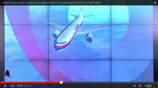
The fuller cloud was being presented in the 3D model but it doesn't take a genius to see that most approaches will cause the plane to be covered with holes from nose to mid-section if a very wide angle or circle would be taken as fragment distribution.
Here's a screenshot (at 35:10) from the 3D angle of the proposed cloud if an approach would have been full-on, to explain at least the blasted cockpit where holes can be seen entering from above and leaving at the bottom. Because of the problems described in the last picture, the orientation of the cloud needs to be turned clock-wise with the cone pointing away from the plane, as the damage is just not there (at least based on the pictures in the Dutch report so far).
jonnyH
Senior Member.
I fail to see the benefit of optimising the system for a situation where the target maintains constant speed and trajectory. This may be effective if it was designed to take down commercial aircraft but one might expect military jets to attempt some sort of evasive action more often than not. There seems little point in making sure the missile flies in a straight line toward the anticipated intercept immediately from launch as it seems probable that the target will change course.But wasn't the whole point of the BUK that it had all those radar and targeting systems? That would mean the BUK software very likely could calculate, as default, the shortest route to estimated point of impact using the vector, target speed and direction but of course also knowing its own acceleration. This would save the most fuel, increase the range and decrease the time to impact and limit reaction times. Quite important if one tries to get to fighter jets or other missiles.
I'm only suggesting a gentle curve during the acceleration of the missile and then a straight line once up to speed and nothing in the quotes you have provided indicate that this cannot be the case.
As @Rob says, on the basis of what we know about the movement of MH17, there is nothing to indicate that the missile needed to resort to "exotic angles" in order to find its target, but gentle curves and route modifications can't be entirely ruled out and may impact the accuracy of the extrapolation by a few degrees.Can we consider the claim that the missile would travel to the 777 using exotic angles, curves or route modifications to be unfounded?
Whether I am right or wrong about this, I don't think failure to account for a curved path is hugely significant, it certainly cannot on its own alter AA's findings to the extent that they would have to conclude Sniznhe was the launch site. I think the apparent failure to factor in the missile velocity probably is significant.
Did anyone else notice the claim that if the missile approach was head on, the shrapnel payload would completely miss something as large as a 777? Seems like a bit of a design flaw to me.
Last edited:
It's a bit tricky to assert your own vector distribution as equally authoritative overruling the one supplied by the manufacturer. What's the exact base for that apart from very basic assumptions? The dispersion cloud surely has certain distinct properties which can only be described by hard evidence from testing and specs. If you want to doubt the manufacturers version, that's possible, but without more solid evidence it remains extremely fanciful.
I'm basing it on their slides.
They say, at 14:00
External Quote:In the static plane the splitter area is two leaves of 56°, approximately. The green arrows show areas of light fraction and the red shows heavy fraction. I'd like to draw your attention to the fact that before installation of this warhead to the missile, the designers carried out dozens of, hundreds, tests of warheads, separately from the missile in assembly with the missile in it, we can have the proofs that not less than 96% of all hitting segments are distributed in this two sectors, or other 4% can have the tolerance of 2 to 3 degrees.
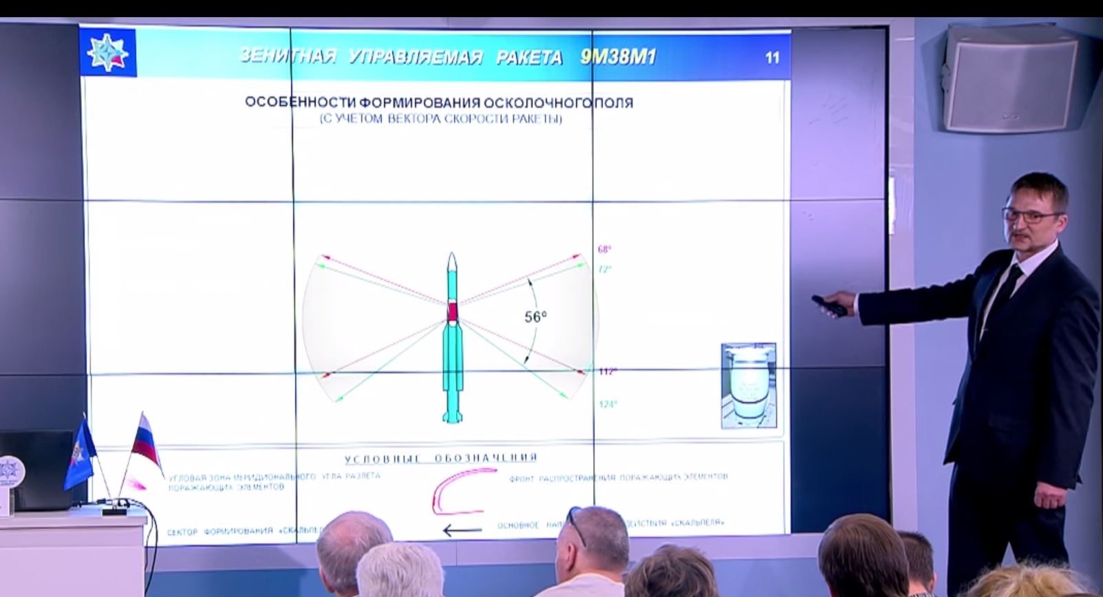
So there they describe an even distribution of velocities.
[15:07]
External Quote:We took into, during the tests, the speed of the missile and the plane were taken into account. The form of the fragment cloud is changing with speed, and two striking fronts are build. These red lines are lighter splinters with higher speed and the violet line shows the front of "I" shaped heavy fraction.
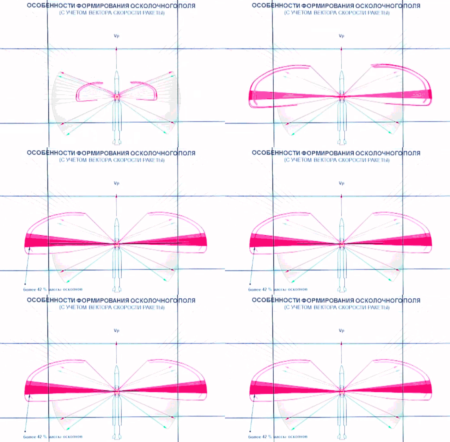
Then they show it modified to account for the speed of the missile and aircraft.
[15:37]
External Quote:The main peculiarity of rocket 9M38M is the special area which is called a "lancet", or the killing lancet, which is perpendicular [inaudible] basically the area of concentration of more than 40% of the all splinter mass, and one half of the whole kinetic energy.
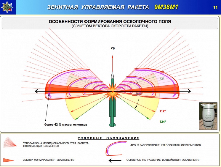
So how do they get this weird velocity distribution? And how do they get some of the fragments traveling backwards? What does the static velocity field look like, and why did they present it as even?
It may well be that the "lancet" design calls for higher speed ejecta in the center of the pattern, however they do not show this in the "static" diagram, and they only say the next diagram is accounting for the speed on the missile (and the plane.)
General question for Mick - can we play around with your model or will that mess up what you have done?
You can play around with it, any changes you make will just be local for you. You can also edit it at a deeper level by making a copy in GeoGebra, there's a "share of copy" at the bottom of the page, or:
http://tube.geogebra.org/material/show/id/1340379
I used the Chrome app to create this:
https://chrome.google.com/webstore/detail/geogebra/bnbaboaihhkjoaolfnfoablhllahjnee?hl=en
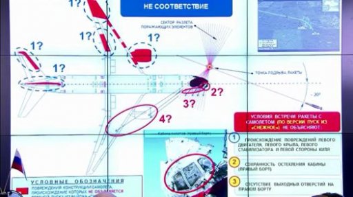
The slide above is used to exclude that particular approach angle, due to the lack of discovered damage on the planes right side (as see in the inset, showing unbroken cockpit windows). However only a minor change in the angle and/or detonation position will mean those cockpit windows will be missed, and the fragments will hit segments of the plane that were not recovered.
This slide also does not seem to have the velocity field adjusted from the static, and has the "suspicious" white arrows going backwards.
This slide also does not seem to have the velocity field adjusted from the static, and has the "suspicious" white arrows going backwards.
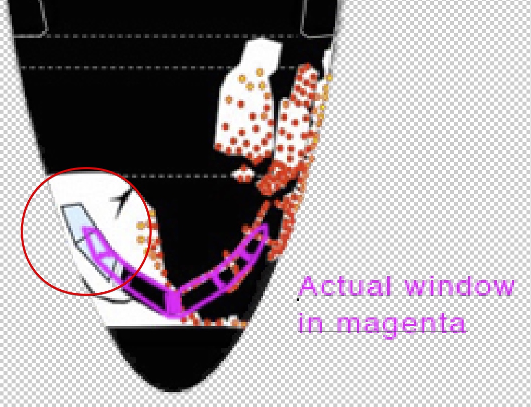
I've updated the tool with a schematic of a 777-200ER, with the Almaz-Antey diagram of damage overlaid:
http://tube.geogebra.org/student/m1342881
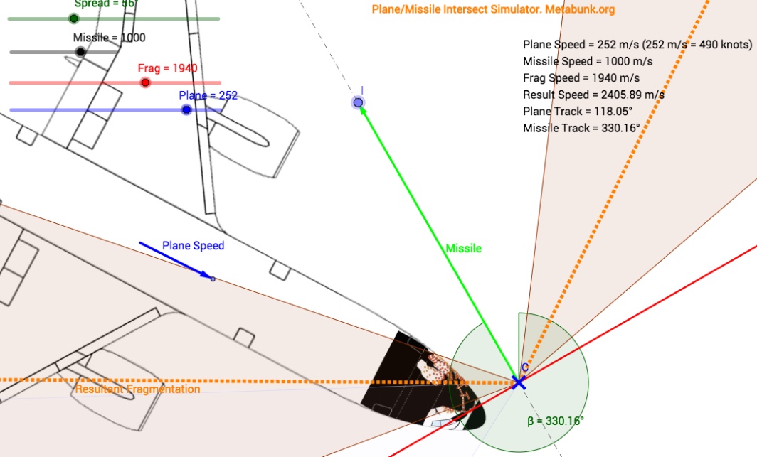
http://tube.geogebra.org/student/m1342881

There's an error in their damage image (and hence in the latest version of my sim, as it uses their image). They have set the windows too far back:
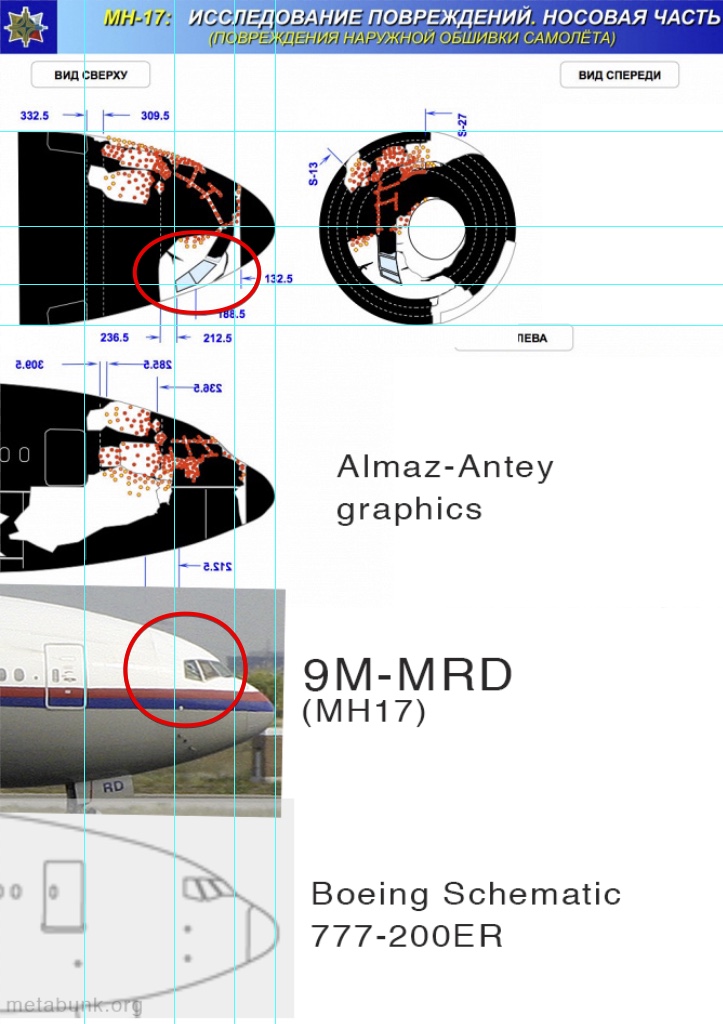
(note I flipped the side view to line it up, it's showing the damage on the left side)
Schematic from: https://commons.wikimedia.org/wiki/File:B777FAMILYv1.1.png
9M-MRD image: https://commons.wikimedia.org/wiki/File:Boeing_777-2H6ER_9M-MRD_Malaysian_(6658133151).jpg

(note I flipped the side view to line it up, it's showing the damage on the left side)
Schematic from: https://commons.wikimedia.org/wiki/File:B777FAMILYv1.1.png
9M-MRD image: https://commons.wikimedia.org/wiki/File:Boeing_777-2H6ER_9M-MRD_Malaysian_(6658133151).jpg
Last edited:
Ole
Member
Hi,
glad to find some serious discussion on the Almaz presentation.
Actually I haven't found any place yet, where Almaz states, that the velocity distribution within the two leaves of 56° is uniform. The most extreme form of a non-uniform velocity distribution of ejecta would be a shaped charge: https://en.wikipedia.org/wiki/Shaped_charge
So I see no _technical_ reason to distrust the manufacturer when he implies a non-uniform velocity distribution for his warhead.
glad to find some serious discussion on the Almaz presentation.
I'm basing it on their slides.
They say, at 14:00
External Quote:In the static plane the splitter area is two leaves of 56°, approximately. The green arrows show areas of light fraction and the red shows heavy fraction. I'd like to draw your attention to the fact that before installation of this warhead to the missile, the designers carried out dozens of, hundreds, tests of warheads, separately from the missile in assembly with the missile in it, we can have the proofs that not less than 96% of all hitting segments are distributed in this two sectors, or other 4% can have the tolerance of 2 to 3 degrees.
So there they describe an even distribution of velocities.
[15:07]
External Quote:We took into, during the tests, the speed of the missile and the plane were taken into account. The form of the fragment cloud is changing with speed, and two striking fronts are build. These red lines are lighter splinters with higher speed and the violet line shows the front of "I" shaped heavy fraction.
Then they show it modified to account for the speed of the missile and aircraft.
[15:37]
External Quote:The main peculiarity of rocket 9M38M is the special area which is called a "lancet", or the killing lancet, which is perpendicular [inaudible] basically the area of concentration of more than 40% of the all splinter mass, and one half of the whole kinetic energy.
So how do they get this weird velocity distribution? And how do they get some of the fragments traveling backwards? What does the static velocity field look like, and why did they present it as even?
It may well be that the "lancet" design calls for higher speed ejecta in the center of the pattern, however they do not show this in the "static" diagram, and they only say the next diagram is accounting for the speed on the missile (and the plane.)
Actually I haven't found any place yet, where Almaz states, that the velocity distribution within the two leaves of 56° is uniform. The most extreme form of a non-uniform velocity distribution of ejecta would be a shaped charge: https://en.wikipedia.org/wiki/Shaped_charge
So I see no _technical_ reason to distrust the manufacturer when he implies a non-uniform velocity distribution for his warhead.
william wiley
Member
They do say that it took a lot of testing to get it so that a small area (the cockpit) took a big hit.So I see no _technical_ reason to distrust the manufacturer when he implies a non-uniform velocity distribution for his warhead.
Actually I haven't found any place yet, where Almaz states, that the velocity distribution within the two leaves of 56° is uniform. The most extreme form of a non-uniform velocity distribution of ejecta would be a shaped charge: https://en.wikipedia.org/wiki/Shaped_charge
So I see no _technical_ reason to distrust the manufacturer when he implies a non-uniform velocity distribution for his warhead.
The diagram seems to show an initial uniform distribution of velocity. They never suggest at that point it's not uniform. They then say they take the speed of the missile into account, and show the second diagram. Without knowing the initial distribution of velocities (from a static missile), you can't calculate the result.
With a static warhead. And they very clearly say it's a 56 degree spread of all the shrapnel, and only 42% is in the "scalpel" area. At no point do they suggest non-uniform initial velocity.They do say that it took a lot of testing to get it so that a small area (the cockpit) took a big hit.
But assuming the initial velocity is non-uniform. If we take their resultant velocity distribution at face value, then we can work backwards to find their initial distribution in terms of a multiple of the missile velocity. First we offset the curve so it matches the 56° spread, so the green line below is the initial velocity distribution
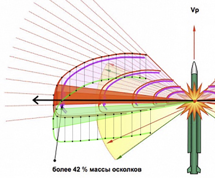
The length of this offset is the speed of the missile relative to that particular representation of velocity vectors. The speed of the missile is assumed to be 1000 m/s, so the length of each of those thin black lines represents 1000 m/s. We can now calculate the spread of velocities by the length of the adjusted vectors. (and you can verify this yourself simply by measuring them on-screen)
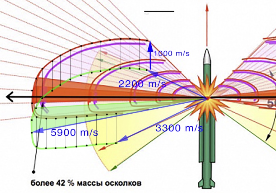
Hence, for the "scalpel" to be at the angle they claim, it would have to be traveling at 5.9x the speed of the missile, or 5900 m/s, with a resultant velocity of just slightly less. And yet they only claim 2400 m/s
Last edited:
jonnyH
Senior Member.
If the maximum speed they claim is 2400 m/s then shouldn't the distance between the missile and the edge of the red shaded bit be taken to represent 2400 m/s as its the longest distance travelled. If you use that to calculate the length of a 1000 m/s vector it ends up being about twice as long as in your picture and makes the static velocity profile point entirely backwards.Hence, for the "scalpel" to be at the angle they claim, it would have to be traveling at 5.9x the speed of the missile, or 5900 m/s, with a resultant velocity of just slightly less. And yet they only claim 2400 m/s
How did you work out the length of your 1000 m/s vector? I've missed something somewhere haven't I, am poised to kick myself.
Ole
Member
Just a quick reply, (I'm still pondering):
Yet if 42% of the mass carries "only" 50% of the kinetic energy that somehow suggests a moderate non-uniformity of velocity distribution, taking into account that kinetic energy is proportional to velocity^2. OTOH that would also depend on whether the bulk of the kinetic energy in the lancet is carried by light or by heavy splinters. If it would be by light splinters, that would be more in accordance with the claim of a strong non-uniformity.
Assuming a non-uniform velocity distribution, the blue vector with caption 2200 m/s would imho represent one of the slower splinters and would have a velocity far below 2200 m/s. The fastest splinters (those with ~2400m/s) would be within the "lancet", i.e. they would move along the black arrow.
Also the 3D Graphics depicting the splinter cloud show a dense front and behind that front a fading cloud of splinters, e.g here:
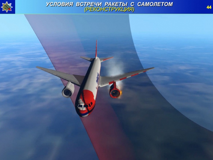
That implies that not only the angular velocity distribution is non-uniform, but also that fragments moving into the same direction have different velocities .
Actually when they say that 42% of the splinter mass and more than 50% of the kinetic energy is contained in the "lancet", they suggest/imply a non-uniform velocity distribution. That is because with a strictly uniform velocity distribution the percentage of kinetic energy and the percentage of splinter mass in a given sector would have to be equal.The diagram seems to show an initial uniform distribution of velocity. They never suggest at that point it's not uniform.
Yet if 42% of the mass carries "only" 50% of the kinetic energy that somehow suggests a moderate non-uniformity of velocity distribution, taking into account that kinetic energy is proportional to velocity^2. OTOH that would also depend on whether the bulk of the kinetic energy in the lancet is carried by light or by heavy splinters. If it would be by light splinters, that would be more in accordance with the claim of a strong non-uniformity.
The length of this offset is the speed of the missile relative to that particular representation of velocity vectors. The speed of the missile is assumed to be 1000 m/s, so the length of each of those thin black lines represents 1000 m/s. We can now calculate the spread of velocities by the length of the adjusted vectors. (and you can verify this yourself simply by measuring them on-screen)

Hence, for the "scalpel" to be at the angle they claim, it would have to be traveling at 5.9x the speed of the missile, or 5900 m/s, with a resultant velocity of just slightly less. And yet they only claim 2400 m/s
Assuming a non-uniform velocity distribution, the blue vector with caption 2200 m/s would imho represent one of the slower splinters and would have a velocity far below 2200 m/s. The fastest splinters (those with ~2400m/s) would be within the "lancet", i.e. they would move along the black arrow.
Also the 3D Graphics depicting the splinter cloud show a dense front and behind that front a fading cloud of splinters, e.g here:

That implies that not only the angular velocity distribution is non-uniform, but also that fragments moving into the same direction have different velocities .
1000 m/s is the speed of the missile. It's just the distance between the two top angles of the before and after vectors in their diagram for the red curve.How did you work out the length of your 1000 m/s vector?
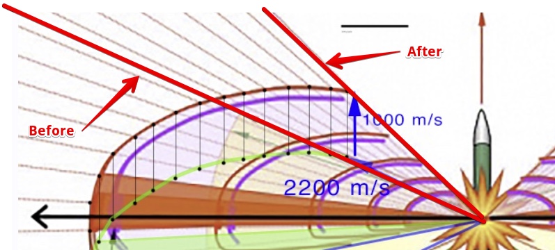
Assuming a non-uniform velocity distribution, the blue vector with caption 2200 m/s would imho represent one of the slower splinters and would have a velocity far below 2200 m/s.
See above, the 2200 m/s is necessary for their diagram to work. If it were slower, then the entire cone would get a lot more of its velocity (proportionally) from the missile, and be at a much steeper forward angle.
For this change in angle of the forward limit of the spread, it MUST be 2.2x the velocity of the missile, so it must be 2200 m/s if the missile velocity is 1000 m/s
Ole
Member
If the maximum speed they claim is 2400 m/s then shouldn't the distance between the missile and the edge of the red shaded bit be taken to represent 2400 m/s as its the longest distance travelled. If you use that to calculate the length of a 1000 m/s vector it ends up being about twice as long as in your picture and makes the static velocity profile point entirely backwards.
How did you work out the length of your 1000 m/s vector? I've missed something somewhere haven't I, am poised to kick myself.
if we assume the velocity to be lowest at the limit of the fragment sector (red line in original graphic), then the 1000 m/s vector is OK. The 2200 m/s should be more like ~1/3 (by eyesight) of the vmax (2400 m/s). vmax is represented roughly by a vector from the center along the black line to the edge of the red shaded bit.
if we assume the velocity to be lowest at the limit of the fragment sector (red line in original graphic), then the 1000 m/s vector is OK. The 2200 m/s should be more like ~1/3 (by eyesight) of the vmax (2400 m/s). vmax is represented roughly by a vector from the center along the black line to the edge of the red shaded bit.
Which means their diagram is wrong as it shows a vmax of 5900.
David Coulter
Senior Member.
A video of a BUK warhead exploding (prematurely) can be found here: http://www.ntv.ru/novosti/141322/video/

It should be noted that the detonation velocity of RDX, a common military high explosive, is 8,750m/s (https://en.wikipedia.org/wiki/Table_of_explosive_detonation_velocities). This is, however, the internal detonation velocity and fragments rapidly decelerate as can be seen in the video. At the 3-5m distance from the target the value of 2,200-2,400m/s seems reasonable. Perhaps @BombDr should get in on this thread......
It should be noted that the detonation velocity of RDX, a common military high explosive, is 8,750m/s (https://en.wikipedia.org/wiki/Table_of_explosive_detonation_velocities). This is, however, the internal detonation velocity and fragments rapidly decelerate as can be seen in the video. At the 3-5m distance from the target the value of 2,200-2,400m/s seems reasonable. Perhaps @BombDr should get in on this thread......
Last edited by a moderator:
Ole
Member
See above, the 2200 m/s is necessary for their diagram to work. If it were slower, then the entire cone would get a lot more of its velocity (proportionally) from the missile, and be at a much steeper forward angle.
For this change in angle of the forward limit of the spread, it MUST be 2.2x the velocity of the missile, so it must be 2200 m/s if the missile velocity is 1000 m/s
Yep, you are right, if your 2200 m/s vector would represent a fragment traveling at ~800 m/s (with static warhead) that fragment would have to travel much more towards the direction of the flight path of the missile due to its initial velocity component of 1000 m/s into that direction. IMHO that doesn't debunk the "lancet" as such, but the "fronts" seem to be bogus.
To get a "lancet" with 2400 m/s that is perpendicular with a warhead moving at 1000 m/s the lancet would have to point to the stern with a static warhead. That angle (to the stern) would be sin^1 (1000/2400) ~ 25°. So in this slide the lancet with static warhead would have to point to ~115°

That indeed would imply a velocity distribution that has the highest velocities to the aft and the lowest to the front. So if there is a lancet, it would probably be more like a cone with a wide opening angle and the lancets pointing slightly to the front.
Ole
Member
That video shows a BUK + warhead exploding before burning its fuel, so we (or at least I) don't know if that explosion is augmented by exploding fuel.A video of a BUK warhead exploding (prematurely) can be found here: http://www.ntv.ru/novosti/141322/video/
To get a "lancet" with 2400 m/s that is perpendicular with a warhead moving at 1000 m/s the lancet would have to point to the stern with a static warhead. That angle (to the stern) would be sin^1 (1000/2400) ~ 25°. So in this slide the lancet with static warhead would have to point to ~115°
Actually tan^-1, so ~22°
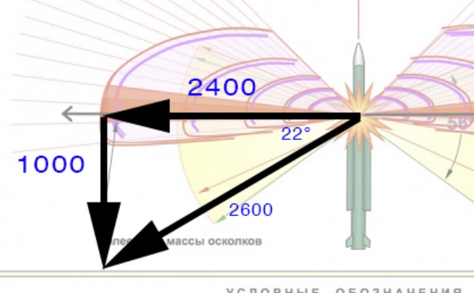
Which is a bit nonsensical from a use of energy point of view, as a chunk of the KE of the explosion is then cancelled out by the KE of the missile. To get a sideways velocity of 2400, you'd need it angled back at 22° and starting at 2600 m/s

