I have made little progress with actual numbers and models for now, but at least I have put the whole problem of finding the possible geometry of the encounter on more firm bases. So I think I can at least present you with a 'math problem' which states the geometric problem, surely not written as a professional mathematician would, but all the pieces should be there and, hopefully, clearly explained. Unfortunately, it's long.
Notice! This post regards only the problem of finding where the F-18 was (and some other things) and how he sighted the Atlas, it has nothing to do at all with the clouds in the video, even if I used the observed clouds flow to constrain a parameter of the problem.
ABSOLUTE FRAME OF REFERENCE
The coordinate system is the usual 3-D representation (used also by Blender):

The position of the origin is arbitrary, but setting it to the position of the Cape Canaveral launch site looks to me the best way to simplify the calculations (I may be wrong).
The spatial orientation of the frame of reference (the direction the axis point to) is arbitrary, but of course it makes things easier if Z is the local vertical, the Y-axis runs from South to North and the X-axis runs from East to West.
Notice this introduces a simplification, therefore errors in the numerical results: the assumption the Earth is flat. It's not the case to revive a diatribe here, my opinion is this assumption just introduces some error in the final numbers, and small errors at that. This looks pretty obvious to me, but in case I will prepare a more detailed explanation. Finicky note: setting the origin of the XYZ reference frame near the midpoint between the (hypothetical) position of the F-18 and the Atlas would reduce this error (and add unnecessary complications).
F-18 COORDINATE SYSTEM
Roll, pitch, yaw:
They are always referenced to the absolute XYZ frame if not explicity said otherwise, indeed I may be better use 'bearing' instead of 'yaw' for clarity, I don't know, any advice on this matter is gladly welcomed.
ATFLIR COORDINATE SYSTEM
[You can skip to the following paragraph, it looks I was too much worried about a possible additional complication]
The ATFLIR sits under the left wing, I guess a couple meters or such from the airplane midplane:

This introduces a very unfortunate complication: calculating where the ATFLIR points to when the airplane roll pitch and yaw angles change becomes complicated because we must also take in account the offsets along the XYZ (relative to the plane this time! This is the single time I use xyz in that sense) axes between the ATFLIR and the origin of the coordinate system of the plane. More simply: we need to take in account the ATFLIR is (say) two meters left, three down and five forward of the centre of the plane.
This is not that difficult to do using matrices to calculate rotations (provided one knows how to do that, and has the tools to do it), but it's just impossible in Blender where we should represent at the right scale both objects in the meter size range (the exact ATFLIR position) and objects in the hundreds of kilometrs range (the lines of sight).
When I did my first (and, I remind everybody, flawed) Blender model I just put the ATFLIR at the airplane center point. But this is dangerous, a difference of one meter in the pivot point of a rotation can make a lot of difference 200km away. This is a limit I cannot trespass by myself, at least using Blender. I have no fear of rotation matrices, but I don't have the tools, that's not good. [Edit: this might not be a problem as big as I thought and bored you about, see post
#230. Edit 2: indeed I now think Mick is right.]
They can both be determined by the video (see post
#108).
I'm not sure I'm using 'declination' in the proper sense, but oh well. By it I mean the angle the ATFLIR does with the longitudinal midline of the F-18:
What the -2° degree elevation shown in the ATFLIR display actually means has been the topic of a long diatribe which I'd rather not reopen. I take it to mean this:
I had it modeled in my first Blender reconstruction and there I found those 2° matter very little. But to be safe they'd better be included in the calculations, with angles one never knows.
KNOWNS, UNKNOWNS AND BOUNDARY CONDITIONS
The question marks in the table mean the variable is an unknown.
The F-18
| X coordinate | Y coordinate | Roll (bank) angle | Pitch angle | ATFLIR declination | ATFLIR elevation | Yaw angle |
| F-18 @t=0s | X? | Y? | 21.8° L | Pt0? | 52° L | -2° | Yw? |
| F-18 @t=34s | X + ΔX? | Y + ΔY? | 27.8° L | Pt34s? | 6° R | -2° | Yw + ΔYw?
ΔYw > 52° + 6° L |
The 'known' numbers have been determined from the video
X, Y: effectively unbounded (call them latitude and longitude if you prefer, but on a flat Earth).
ΔX, ΔY: rather strictly bounded knowing how much an F-18 can turn at Mach ~0.58 in 34s. Little relevant anyway because they are small compared to the scale of the encounter (they are much more relevant for realistically modeling the clouds, but that's not the point here). They could just be assumed to be zero without introducing much error.
Pt0, Pt34s: very important unknowns, as all angles are in this kind of problems. Constrained by what an F-18 can actually pitch up (surely it was not pitching down). Notice: the notation P, P+ΔP would not be useful at all in this case.
Yw, ΔYw: very important unknowns. Yw is unconstrained (from 0° to 360°), but ΔYw is constrained to be towards the left and greater (but I guess at least 1.5 times greater) than the total degrees the ATFLIR moved (52° + 6°).
This is necessary to explain the 'reversed' visual flow of the clouds in the video, see post #200.
The Z coordinate (altitude) of the F-18 can be safely assumed to be constant at 25kft =~ 8333m
The Atlas
| X coordinate | Y coordinate | Z coordinate |
| Atlas @t=0s | XAtlas?(tAtlas_zero?) | YAtlas?(tAtlas_zero?) | ZAtlas?(tAtlas_zero?) |
| Atlas @t=34s | XAtlas(tAtlas_zero? + 34s) | YAtlas(tAtlas_zero? + 34s) | ZAtlas(tAtlas_zero? + 34s) |
tAtlas_zero: a very important unknown. It's the time, referenced to the Atlas, which corresponds to the time the Gimbal video begins. That is to say, it tells us where on the Atlas trajectory the video started (it ended 34s later).
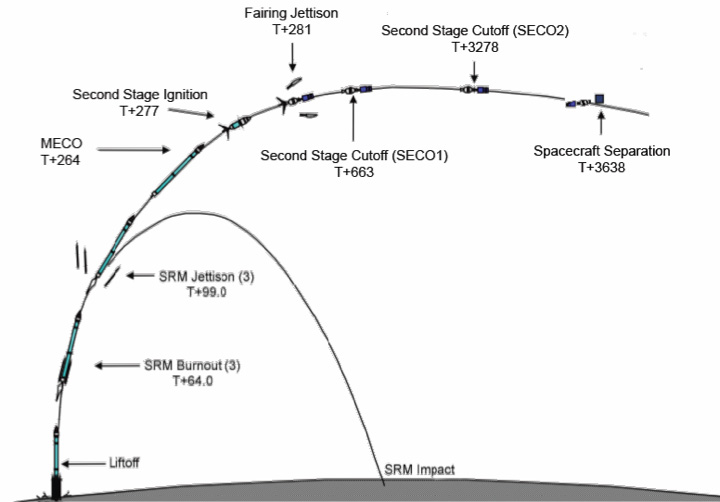
In theory we would not need to worry anymore about the Atlas, the Atlas trajectory [XAtlas(t), YAtlas(t), ZAtlas(t)] is in principle knowable. But in practice we don't know it, what we surely rather well know is how it looks on the XY plane, the trajectory on the map (*), then we (I, at least) know two points with a reasonable precision (**)
(*) mathematically: we know YAtlas = f(XAtlas), or an equivalent equation.
(**) mathematically: I know the two vectors (read: points) Atlas1 = { X1, Y1, Z1 } and Atlas2 = { X2, Y2, Z2 }
STATEMENT OF THE PROBLEM
Determine the full set of vectors (read: solutions) { X, Y, ΔX, ΔY, Pt0, Pt34s, Yw, ΔYw, tAtlas_zero }, satisfying the above stated boundary conditions, so that the line of sight of the F-18 ATFLIR at time t=0 and t=34s (*) will point straight to the Atlas position at the corresponding times (**) (***)
Just one solution would already be more than enough for a dubunk though, I guess, the full set of solutions is probably an overkill. Expecially if the solution found happens to be near a suitable cloud on a satellite meteo map, but the clouds are a wholly different and indipendent matter.
(*) Which is a function of the position and spatial orientation of the ATFLIR at those time, which in turn also depends on the position and spatial orientation of the F-18, which are the numbers the problem asks for.
(**) which is a function of tAtlas, which must be found, and XYZAtlas(t) which in principle could be known as a datum.
(***) oh c'mon, 'straight'... let's allow a minimum of angular error
I bet any young US Naval Aviation officer in training would be able to solve it (or maybe he'd find there are no possible solutions, in that case the Gimbal could not possibly have been the Atlas), and many other professionals could relatively easily too. Finding such person here on MB would really be a great strike of luck!


