Could Girder A2001 Possibly Have got Past the Side Plate on Column 79?

If it took 180 kips to shear the bolts, could that be enough to damage the side plate and/or girder flanges and push past? I thing perhaps, but it depends on some things we don't know, or at least haven't been discussing here.
The bolts shear in a symmetrical fashion. Afterwards, one corner of the girder will come into contact with col 79. This causes asymmetric out of plane bending in the bottom flange as well as twist in the column.
This increases the chance of local damage to the edge of the beam that is meant to be restrained by the side plates. Increasing the probability of push of failure in the cooling cycle
 
There are a couple of questions I have.

First the girder comes in at an angle to Col 79. This would put a large asymmetric bending on the bottom flange, which would force any buckling to start on the edge of the flange that Tony says would hold the beams in place

Interesting this tends to twist the column away from the beam supporting it. So general column roTation in fire could be an issue.

Secondly could tolerances be important.. Yes there is only a theoretical gap of what looks like half an inch. This could get used up in construction and the steel fixers would be happy to gouge hole to get beam to fit. The bolts are only erection bolts and this would be normal construction practice.

In addition the beam would try and rotate when concrete was added So it would be reasonable to assume a worst case that the beam was in contact at initiating stage. I don't think Arup or Wedlinger looked at this but unlike Hulsey they never claimed to have considered all possibilities And if the beam expands by 1.8in relative to the column restrained then it would cause immediate damage to the girder

The bottom flange sits on the connection plate and bearing plate which is connected to the cover plates. I can't see why you would get anything other than uniform pressure beneath the flange bearing?

Tolerances could be important if longer or shorter members compromise bearing widths and fit but where does the hypothesis stop if you start adjusting connectivity?

Even with no pre-camber the weight of concrete will not shear the bolts causing the girder to touch the column. I'd be careful with the 1.8" concept. 3.6" is the calculated increase in length of A2001 due to temperature increase but that is not necessarily 1.8" each end! If restrained that increase will cause a large reaction, if unrestrained an increase in length.
You have to accept a lot of dislocation of steel, shear studs, decking and concrete before there's any separation of A2001 and column 79 at all during the heating phase?
 
[Note: these animation are based on inaccurate schematics that don't match the construction drawings, left here for purposes of discussion, but see later animation]

Hi Mick, I'm new here, I've only been looking into the whole 9/11 conspiracy theories over the past year, it appears to me that the 9/11 truth movement have lost quite a bit of traction after risking their reputation using Dr Hulseys flawed analysis of the girder you're demonstrating here, in your opinion is this the last card that a.e.truth have dealt to prove their case ?
 
Hi Mick, I'm new here, I've only been looking into the whole 9/11 conspiracy theories over the past year, it appears to me that the 9/11 truth movement have lost quite a bit of traction after risking their reputation using Dr Hulseys flawed analysis of the girder you're demonstrating here, in your opinion is this the last card that a.e.truth have dealt to prove their case ?

Hulsey has not really released his full analysis, so while his preliminary presentation was certainly flawed (see: https://www.metabunk.org/debunked-uaf-study-shows-wtc7-could-not-have-collapsed-from-fire.t9056/ ) there's presumably going to be other cards for them to play.

AE911 is not going in away, in part because their success is largely based on an argument from authority, and many people buy that. Their physics is all wrong (laughably so sometimes), but most people don't understand physics, so they see "lots" of architects and engineers saying it was a controlled demolition, and no similar group opposing the the idea, so they go with the idea they prefer.

They will continue to play the exact same cards. The best way of addressing this is to continue to build a body of evidence and accessible explanations that directly address their claims. The reason this is still somewhat lacking is that most qualified people think that AE911 is laughable, and not worth their time. This creates a bit of an illusion of authority on the AE911 side.
 
...
AE911 is not going in away, in part because their success is largely based on an argument from authority, and many people buy that. ... most people ... they see "lots" of architects and engineers saying it was a controlled demolition,
... This creates a bit of an illusion of authority on the AE911 side.
One of the most interesting developments I have seen on AE911Truth is that they lost three quarters of the signatures from architects with the title "FAIA". "FAIA" is an acronym for "Fellow of the American Institute of Architects". This title is bestowed as a medal of honour to members of the AIA who have distinguished themselves with lifetime achievements. Richard Gage, himself an ordinary member of the AIA, is always very keen on flaunting his title "AIA", and apparently was proud of the 19 FAIA signatures (out of, I think, about 3,000 current FAIAs), for about half of them were listed at the very top of their list of now 2,900+ signatories.

But 13 of these 19 FAIAs have been deleted from the list recently (about 2 months ago, if memory serves), and of the 6 remaining (do a local search of the string "FAIA" in the above linked page), 1 (Eason Cross) has had his profile appended with the word "Deceased".

The best explanation for this is that AE has recently done an audit of their FAIA signatories and found that only 5 of 19 actually still support them (if they ever did) and are alive. If this is true, then this calls very much into question the validity of that "2,900+" number - could be as little as 800.
 
AE911 are also very unlikely to back away from their case that the girder could not have walked off its seat. Again they exploit the lack up understanding of the average person, and make a compelling sounding case that failure of that connection is impossible. Prior work by @Tony Szamboti and @gerrycan does seem to show that when considered in abstract isolation as a local subsystem the girder is left an inch or two away from failure. They took that and then made a rather extreme leap to claim the entire collapse due to fire was impossible. Hulseys result was rather different and I think they have struggled to reconcile the two analyses. Did the girder not move quite enough (Tony/Gerry), or did the entire building expand like a balloon with no connection failures (Hulsey)?
 
The Hulsey philosophy of global movement does not make sense. Of course there would be global movement that would be consistent with the heat of the slab and the lateral stiffness of the surroundings.
However the relative movement at the connection comes from the relative heat of the beam to the slabs. If there is no relative heat there is no deflection of the beam and no relative movement. If the beam is hotter than the slab then it will expand relative to the slab causing beam deflection and relative movement at the connection
You would expect relative movement at the connection and beam deflection.

I have heard that the tops of the beams in the gaps between the deck was not protected. This would put a lot of heat into the beam and a lot of differential shear stress at the shear stud locations this is a common problem in beam fire protection.

In addition heat transfer would increase if there was reduced thicknesses of fire protection or brackets connecting to steel or if there were edges at openings. A 100degC change on a 40ft beam causes 0.6in extension . The longer the span and the higher the temp the larger the movement. The movement can cause connection buckling, bolt shear etc etc

Beams that were designed as simply supported and had nominal end fixity can suddenly find there is enough compression in the bottom flange to cause local buckling.

It will be interesting to see how Hulsey explains this.
 
I don't know why my last post was removed, maybe someone could tell me why, but I'll rephrase my guestion, So my question is that if the floor truss broke off the perimeter wall joint first wouldn't this account for the truss to break the bolts on column 79 and slide off ? This might explain why it wasn't necessary for the floor truss to slide pass the flange.
 
So my question is that if the floor truss broke off the perimeter wall joint first wouldn't this account for the truss to break the bolts on column 79 and slide off ? This might explain why it wasn't necessary for the floor truss to slide pass the flange.
There is no evidence that the seat the beam was sitting on broke off. The bolts that broke off connected the beam to the seat.
The 'seat' is like a wall bracket that holds up a shelf. The bolts that broke were the ones that bolted the 'shelf' to the wall bracket itself.
 
I don't know why my last post was removed, maybe someone could tell me why, but I'll rephrase my guestion, So my question is that if the floor truss broke off the perimeter wall joint first wouldn't this account for the truss to break the bolts on column 79 and slide off ? This might explain why it wasn't necessary for the floor truss to slide pass the flange.

Perhaps you might explain better with a diagram? The question here is how the girder A2001 could possible move far enough off the seat to fail. Are you suggesting it might have moved north?

And make sure you read through the thread before answering. And if you are really interested there's more discussion here:
https://www.metabunk.org/critical-errors-and-omissions-in-wtc7-report-uncovered.t2332/
 
I'm surprised at what a riveting read this is, I think OP needs to reflect on the title of the thread. When you are reinforcing your grand theory by arguing what happened to a girder in a chaotic system it suggests a lack of evidence overall.
 
...so it could be pushed off.
I assume you meant it could not be pushed off.
It would have been trapped by the flange of column 44.
How so? Girders and beams which connected to columns other than perpendicular had extended seats, connecting the girder outside the flange of the column. This is NIST drawing of A2001 connection to column 79. Column 44, the other end of A2001, likewise was an angled connection:
NISTB7angledseatsA.png

The column flange could not have "trapped", or prevent lateral movement of girder A2001.
Bolts were erection bolts; temporary bolts to ensure beams and girders were held in place during construction.*
Additionally, NIST "found no evidence that girders or beams were welded to the seats."* That would leave only the bolts to resist any pulling, lateral, or twisting load on the connection.
* https://tsapps.nist.gov/publication/get_pdf.cfm?pub_id=861611 page 348.
 
Not all beams were attached to the webs.... beams were attached to flanges as well. For erection purposes a beam's length needs to be shorter than the distance between the beams it spans between. The connections had seats and or knife connections using angles and plates, bolts and welds and beam stubs.
 

Attachments

  • steel connections.pdf
    68.2 KB · Views: 507
20170921-100949-vc4yt.jpg

So looking at the bottom hole, it's 6 3/16" perpendicular from the column face. On 9114"

20170921-101239-t5xzu.jpg
4 1/4 from the end of the girder. So the largest gap between girder and column is 1 15/16. 1.94", not a lot of leeway on the 1.8 (if that reflects reality).

Some interesting problems with those diagrams though, here's two numbers 1/2 and 3/4
20170921-103641-42cbp.jpg

However the 1/2 dimension is bigger than the 3/4 when it should be smaller.
Ya got me ta thinkin so I did the math. It took a while to think this through but I believe I have it right.

5-13/16 east bolt hole to column face

4-1/4 bolt hole to end of girder

5-1/2 between bolt holes leaves 3” of flange on either side.

Angle is 7/8:12 (round to 1:12) 3/12 = ¼ subtract 1/4 from the distance between the column face and the flange at the bolt hole on the east end of the flange

5-13/16 – 4-1/4 = 1-9/16 – ¼ = 1-5/16 distance on east side of flange to column face

6-3/16 west bolt hole to column face

Angle is 7/8 : 12 (round to 1”) add 1/4 to the distance between the column face and the flange at the bolt hole to the west end of the flange

6-3/16 – 4-1/4 = 1-15/16 + ¼ = 2-3/16

When girder expands until the east end of the flange is up against the column face

Subtract east gap 1-5/16 from west gap 2-3/16 = 7/8 =.875 inches
1.8 = ~1-7/8 So there would be about 1 inch of side plate to trap the girder.

* * * * * * * * * *
NIST knows that the girder would be trapped by the side plate.
1580298233144.png
 

Attachments

  • 1580298183487.png
    1580298183487.png
    390.6 KB · Views: 430
Last edited:
Right :) We are off topic again but just FYI,

1580283174008.png
Just FYI, you posted a square connection drawing. A2001 to column 44 was an angled connection.
Your claim that the girder would have been "trapped" by flanges of column 44 is demonstrably false, per the NIST Report drawing of angled connections.
NISTB7angledseatsA.png
 
Just FYI, you posted a square connection drawing. A2001 to column 44 was an angled connection.
Your claim that the girder would have been "trapped" by flanges of column 44 is demonstrably false, per the NIST Report drawing of angled connections.
NISTB7angledseatsA.png
You need to go back and look at the first page(s) of this thread
https://metabunk.org/threads/could-...ve-got-past-the-side-plate-on-column-79.9069/

The actual blueprints indicate less room for maneuvering than NIST's diagram suggests. Still certainly not impossible, but Tony argued that the girder would have expanded.

 
Aren't all these calculations, drawings and diagrams based on the assumption the construction was still complete rigid and intact as it was build?
What if the column already started to buckle a bit, wouldn't it allow for much more space for things to fail?
 
You need to go back and look at the first page(s) of this thread
https://metabunk.org/threads/could-...ve-got-past-the-side-plate-on-column-79.9069/

The actual blueprints indicate less room for maneuvering than NIST's diagram suggests. Still certainly not impossible, but Tony argued that the girder would have expanded.

I understand there are questions about actual dimensions of different renderings, but that doesn't excuse substituting a square girder/column connection rendering for the actual angled connection, in order to state the girder would be trapped by column flanges.
 
I understand there are questions about actual dimensions of different renderings, but that doesn't excuse substituting a square girder/column connection rendering for the actual angled connection, in order to state the girder would be trapped by column flanges.
So where's the actual A2001->C44 diagram?
 
Your math needs a diagram.
I was using the drawings from 1091 and 9114 that you posted in the post I was replying to. You can click on the links in your post to see them. I don't have the time or facility to make a diagram nor is it necessary. The drawings are enough.
I neglected to note that the flange of the girder was 11-1/2 inches wide before
5-1/2 between bolt holes leaves 3” of flange on either side.

I can do this much to show how to transpose the angle:

1580355822637.png
 
Last edited:
So where's the actual A2001->C44 diagram?
Best I can tell, NIST diagrammed the A2001 to C79 only, as an example of angular girder/beam connections to columns.
"Where the floor beam framed into an exterior column at a skew angle, the seat angle was replaced by a plate. Figure 8-21 shows the seat connection at Column 79..."*

*NIST NCSTAR 1-9 Page 348
 
Side plate 1' beyond girder flange.png

A 5-13/16" from center of east bolt hole to column face

B 6-3/16" from center of west bolt hole to column face

6-3/16 – 5-13/16 = 3/8" difference in distance to face of column 79

flange of girder A2001 was 11-1/2 inches wide
Girder sizes.png

C 5-1/2" between centers of bolt holes leaves 6 inches of flange

D angle was 7/8:12 so 6 inches = 7/16" of difference in distance to face of column 79

3/8 + 7/16 = 13/16" difference in the distance to the face of column 79 between the east corner and the west corner of the flange

E column 79 side plate extended 1.8 or 1-13/16" beyond the face.

1-13/16 – 13/16 = 1 inch of side plate extending beyond the girder flange when the east corner of the flange was up against the face of column 79.

Girder trapped by sideplate.png
 
Last edited:
Column 79 dimentions and plate size e.png
"Column 79 at Floor 14 – W14x730 with two 26-in. x 2-in. side cover plates" NCSTAR 1-9, Vol. 2, p. 694 [PDF p. 356/760]
Side plates 26 inches - Column depth 22.4 inches
26 – 22.4 = 3.6 inches - divided by 2 =1.8 inches protruding on either side of the column
 
The initiating local failure that began the probable WTC 7 collapse sequence was the buckling of Column 79. This buckling arose from a process that occurred at temperatures at or below approximately 400 °C (750 °F) NCSTAR 1A, p. 21 [PDF p. 63]
Content from External Source
Continued axial expansion of the girder caused it to bear against the face of Column 79, generating large axial forces that led to failure of the bolts connecting the girder to Column 44. When the girder temperature had reached 398 °C, all four erection bolts at Column 44 had failed, leaving the girder essentially unrestrained against rotation at both ends. NCSTAR 1-9, Vol. 1. p. 352 [PDF p. 396]
Content from External Source
NIST is saying that the damage that began the collapse (in their hypothesis) happened at or below approximately 400 °C. And that at 398 °C, A2001 was bearing again the face of column 79.

But, as noted above, if A2001 was bearing against the face of column 79 it could not have gotten by the side plate.

NIST shows A2001 trapped by the side plate in Figure 8-26
1581229017218.png

But that's a different simulation, one in which A2001 fails by buckling (and the building still collapse)


Discussed two years ago, here
https://www.metabunk.org/threads/wt...t-key-in-nists-global-model.9427/#post-217761
 
But that's a different simulation, one in which A2001 fails by buckling (and the building still collapse)


Discussed two years ago, here
https://www.metabunk.org/threads/wt...t-key-in-nists-global-model.9427/#post-217761
The building does not collapse because the preliminary analysis in Chapter 8, designed to get the shear studs to fail, stops when A2001 is pulled off of its seat to the east.

In that analysis, NIST assumes the beams were heated to 600°C and the A2001 girder to 500°C. NIST carried forward the shear stud failure but not the buckling of A2001 because in their final collapse analysis the floor beams and A2001 were only heated to about 400°C.
“The initiating local failure that began the probable WTC 7 collapse sequence was the buckling of Column 79. This buckling arose from a process that occurred at temperatures at or below approximately 400 °C (750 °F)” NCSTAR 1A, p. 21 [PDF p. 63]
Content from External Source
 
The Chapter 8 simulation is too often used by debaters on all sides of the issue when it shouldn't:
NIST did it, a very local model, with temperatures going perhaps a bit higher than one might expect, to see what types of failures would arise: Would failure mode A or B or C occur first? The point being that IF A happens first, AND A relieves B of its stresses immediately, THEN the subsequent full model (Chapter 11 ANSYS) needs not look for occurrences of B.

They did this to limit the degrees of freedom in the ANSYS model and make it more computationally more feasible.
It was a trade-off.

Whatever happened or didn't happen in the Chapter 8 sim run does NOT inform us about what did, would should happen in the subsequent larger models.
 
To clarify the topic, I have renamed this thread:
Could Girder A2001 Possibly Have got Past the Side Plate on Column 79?
Yes, it is possible, based upon known evidence from FDNY.
The SW corner bulge between floors 10-13, and creaking girders noted upon interior inspection.
The bulge indicates loss of lateral support, at least in that part of the structure.
Creaking girders indicate an unstable structure, shifting loads.
This evidence makes it entirely possible that either column 79 moved SW, or column 44 moved north, or both, enough for A2001 to clear the column flange on either end.
There was no bulge in the SW corner between floors 10-13 because the SW corner between floors 10-13 had been taken out by debris from WTC 1.
Firefighters heard creaking. There was no mention of girders.

1582438610469.png
 
True. But the expansion of the floor beams and the A2001 girder would be the same at 400 °C.
So what? The location in 3D of columns 79 and 44 (and all others) would be different, so this information about girder expansion is at most half the information you'd need to conclude anything.
 
So what? The location in 3D of columns 79 and 44 (and all others) would be different, so this information about girder expansion is at most half the information you'd need to conclude anything.
???
Columns 79, 44 and the girder connecting them would not be in a different location, nor would anything else. The 3D view would not change that. It would only change the view perspective which would have no effect on the expansion of the floor beams as they pushed the A2001 girder to the west and the expansion of the A2001 girder as it was pushed up against the face of column 79.
 
???
Columns 79, 44 and the girder connecting them would not be in a different location, nor would anything else....
Ahh! Now I see where your problem is!

You assume that the only thing heated and deformed in the fires was that single girder and the beams framing into it from the east, right?

Well, wrong.

The building had been on fire for hours on several floors surrounding that area. Girders and beams would have expanded and/or sagged on different floors at different times, pushing and pulling the columns around. There were more connection failures elsewhere.

It is extremely unreasonable to assume cols 79 and 44 were pristine and had not previously been affected by what was the largest, most devastating building fire in US history.


The 3D view would not change that.
I should have said 4D. Time is important.

Someone, I forgot who, described what happened as an intricate dance of hundreds of individual structural elements, giving rise to a complex motion in 4D (3 space dimensions plus time).

By the way, even Hulsey's draft shows that floor 13 expanded differentially. It not merely translate or rotate, keeping all distances equal at all times, he showed that distances between columns would change. (I would of course not give much stock in Hulsey's analysis here - he does the 3D thing, ignores entirely that was time elapsing.)

See:

HulseyDraft Fig 02-56 Displacement of Floor 13 in the x (horizontal) direction.jpg

This figure shows how column 79 moved between 1.4 and 2.1 inches relative to some useless reference, while column 44 moved between 0.7 and 1.4 inches. The columns in the east wall moved between 3.5 and 6.3 inches.

So you see, clearly columns 79 moved some non-zero, plausibly significant distance relative to the relevant surrounding columns.
 
You assume that the only thing heated and deformed in the fires was that single girder and the beams framing into it from the east, right?
No.
The building had been on fire for hours on several floors surrounding that area. Girders and beams would have expanded and/or sagged on different floors at different times, pushing and pulling the columns around. There were more connection failures elsewhere.
Bending and sagging floor beams and girders could NOT push the columns around because the columns were surrounded by cement slabs. There would be movement due to thermal expansion but everything would expand together.

It is a self evident axiom of physics that things cannot expand inward, only outward. So Hulsey's central point of no expansion is correct.

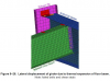
Column 79 is in the center of the pale green which means that it was displaced about 1-3/4 inches from the center of the building.
Column 44 is in the yellow area and closer to the pale green than the pale orange so it was displaced abut 1-1/4 inches from the central point.
That would put the area between columns 79 and 44 in compression.
And it's the thermal expansion between columns 79 and 44 that we are concerned with.
It is my understanding that concrete expands at 85% the rate of structural steel so the differential is inconsequential.

Here is the Math with graphics.

A2001 - east end of flange to column face (flange)

1582546887646.png
center line of bolt holes at center line of seat (and girder) to column face (flange)
A + B
5-13/16 + 6-3/16 = 12 divided by 2 = 6 inches

center line of bolt holes to end of girder 4-1/4 inches
center line of A2001 girder to face of column 79 - 1-3/4 inches

1582546964051.png
girder flange 11-1/2 inches wide divided by 2 = 5-3/4 inches
east end of girder flange 5-3/4 inches from girder center line
angle is 7/8:12 or 7/16 in 6 inches so:
1-3/4 – 7/16 = 1-5/16
east end of girder flange just over 1-5/16 inches from column face


A2001 girder 45 feet
K3004 floor beam 53.57 feet – expands 3.3 inches at 400 °C
45 divided by 53.75 = .837
45 is 83.7% of 53.75
3.3 x .837 = 2.76 or 2-3/4 inches
A2001 expands 2-3/4 inches at 400 °C

1582547150750.png
 
Last edited:
@Christopher 7, in the calculations you've presented re the expansion of A2001 at 400°C, is it your assumption that the entire beam was continuously heated to a single, uniform temperature?

(Note that I am leaving aside the other points you raised, such as the ridiculous claim that the concrete decks and steel framing members would in all temperature conditions act in unison, which NIST demonstrated would not be the case and which has been shown to you to be false in other threads. I just want to drill down into what you are presenting here as your positive model.)
 
Back
Top