Oroville Dam Spillway Failure

Status
Not open for further replies.
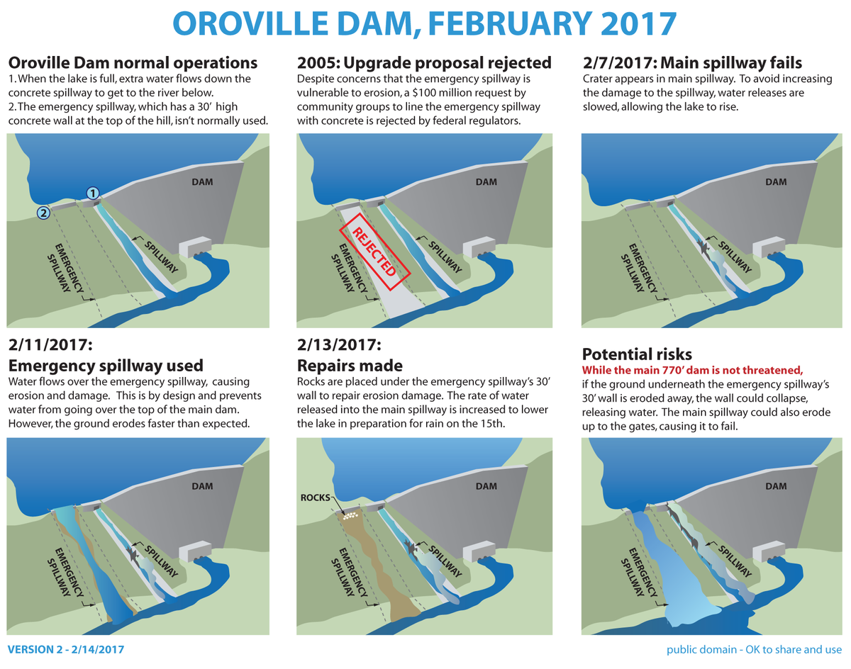
Just a few notes on the actual main spillway fracture plus two links on the oldest working dam in the world circa, 1309-1304 BC, showing its value for money. In my locality, a slightly newer dam built 1861.

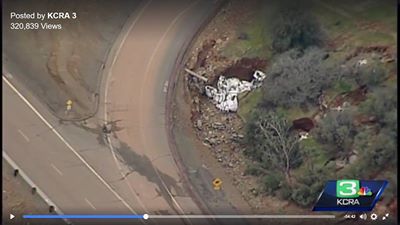
I have reason to submit that the original fault in the emergency slipway has been caused by incorrectly angled concrete deck that caused suction due to release of compression as the water travelled downhill.

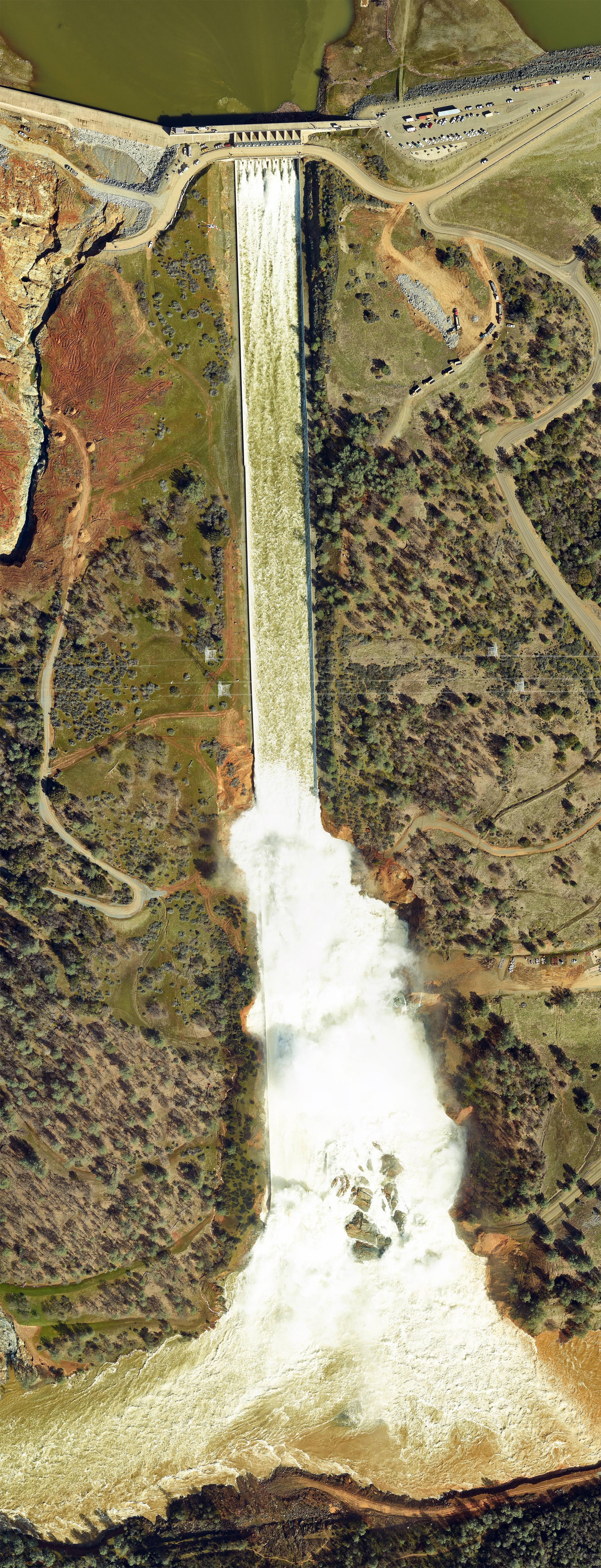
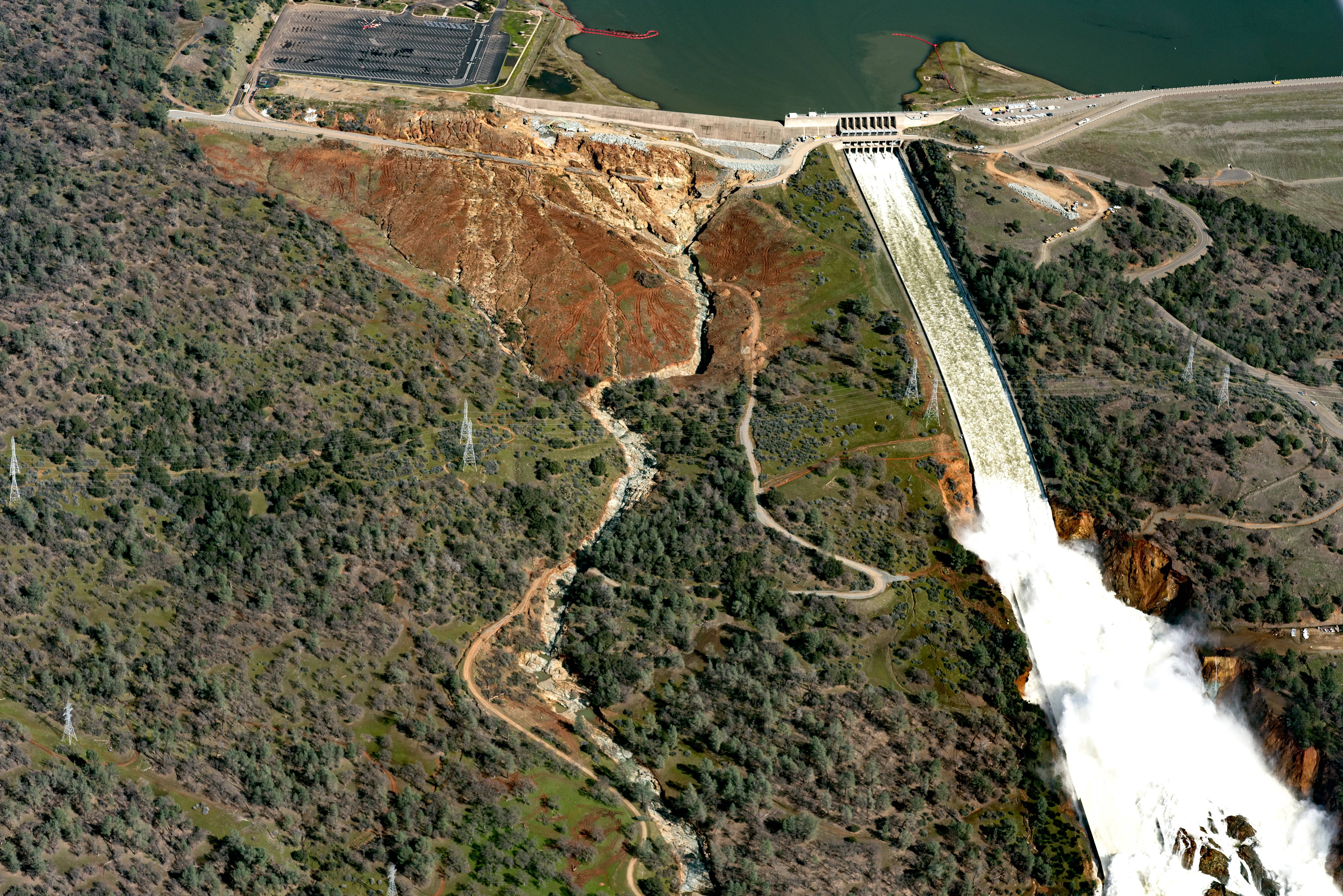
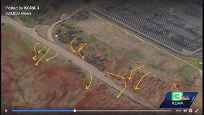
As one can see from the numerous photographs on this discussion, the angle of the slipway changes at about 40% down slope. The down flow of water under steady compression is forced to amplify speed causing the top 25-30% of down flow to increase speed thus causing a decompression or suction against the rest of flow. This suction at an estimated 200 metric tons per Square Meter would be sufficient to start a crack propagation phenomenon usually known as a subcritical crackhttps://www.metabunk.org/#_edn1. As it looks as if the concrete was not anchored via pilings etc at this area, the vertical stress would be sufficient to cause failure. Note that the failure is downhill of the actual angle change as it takes time for the decompression or suction effect to reach peak.

During a shear test, peak stress is located within the large strain zone at a strain value ɛf defining the material failure. Deviatoric peak stress qf, failure strain ɛf and the stiffness at very small strains are parameters needed to calculate both rigidity and degree of small strains.


ETan Very small strains

Esec

Eo

f

qf

q = ( a-r)


Failure ETan and Esec

Eo

0.1%

ETan

Esec

log

Large strains


Figure 1. Schematic stress-strain and stiffness-strain curves

for a natural soil (from Atkinson, 2000).


Non-linearity of soils. These are two parameters are used to determine the stiffness decay curve of soils (Atkinson, 2000). Rigidity is defined as the ratio of stiffness to strength (E/qf=1/εf) while the degree of non-linearity can be defined as the ratio of failure strain to a reference strain εf/εr. Using these concepts, Atkinson (2000) presented a simple non-linear stiffness-strain curve in terms of the tangent Young’s modulus Etan that is mathematically defined as:


Etan

E0=

1−εf

εr

1−εf

ε0r(1)


Where E0 is the Young modulus at very small strain for a strain ε0, εfis the strain at the peak Deviatoric stress

In addition, ris a soil parameter which includes the degree of non-linearity. According to Atkinson (2000), f saturated conditions, rcan vary from 0.1 to 0.5.[ii] I have used soil as it is the basic knowledge but the principle is the same for any particle however bonded.

The presence of water in building materials can lead to cracks which result from freeze/thaw cycles or, in combination with very low permeability's, to the spalling of high performance concrete exposed to fires. In addition, the invasion of water in building materials provides a mechanism and path for the penetration of deleterious materials like chloride and sulphate ions. While the primary transport mechanisms by which chloride and sulphate ions ingress concrete are diffusion and capillary action, diffusion alone can be a very slow process, hence it may be that capillary transport, especially near an unsaturated concrete surface, is the dominant invasion mechanism. Clearly, an understanding of moisture transport in concrete and mortar is important to estimate their service life as a building material and to improve their quality[iii]. As such, as this is an earthquake area, has the emergency slipway suffered cracks that were actually deeper than known.

Several posts have noted that there may have been cavitations[iv] that may have or presumably did cause shock waves, which would have occurred under the down flow angle, change as noted.

To fix the problem in the future;


https://www.metabunk.org/#_ednref1 http://www.icevirtuallibrary.com/doi/abs/10.1680/geot.2003.53.2.289?journalCode=jgeot

[ii] https://www.researchgate.net/publication/277677537_Suction_effects_on_the_pre

failure_behaviour_of_a_compacted_clayey_soil

[iii] http://ciks.cbt.nist.gov/~garbocz/captrans/node1.html

[iv] https://en.wikipedia.org/wiki/Cavitation
 
Apparently, someone shot a bunch of high resolution images from a plane yesterday. Imgur album


Photomosaic of the main spillway: imgur link (for anyone who may be interested in counting trucks, I see 4 semi trucks, a excavator, 2 dozers (one large and one medium) as well as 4 offroad dump trucks at the rock stockpiling yard in to the right of the main spillway (facing the dam). I also count a concrete pumper, another offroad dump truck, a large dozer and a cement truck to the left of the main spillway and/or heading toward the far end of the emergency spillway. There are also a couple of what look like semitrucks with lowbed trailers attached in the spillway parking lot):


Another (wider) picture showing both spillways: imgur link


The people who posted these said that they had the SFGate photographer who took the pictures for this article with them: http://www.sfgate.com/news/article/Courting-disaster-at-Oroville-Dam-key-10932701.php

Aaron Z
 
Interesting video, here's those bulldozers in context (flipped correctly)
20170214-233054-p4g7z.jpg

Seems like it would take a long time to dam the backflow there. However they have several days. And they can always undam.

If they are damming the backflow in the pond then that must be in case of a quite large release of water. But is there some other explanation for these dozers?

here is an article discussing the work being done down on the river and in front of the main dam:

http://www.chicoer.com/general-news...lle-dam?utm_source=dlvr.it&utm_medium=twitter
 
Those two bulldozers might not be trying to control water. They might be preparing a space for a pile of dredged material. The optimum place to put dredged material is a flat space just above river level, whether it will remain there or be trucked away later.
 
.
The main spillway chute may have lifted and ruptured due to the venturi effect. The water or air below the chute is static, while the water above is flowing at a great rate, reducing the pressure. It is the same differential flow that lifts a B747 into the air – 450 tonnes of metal hanging on a very small differential airflow.

Not sure if engineers take the venturi effect lifting the concrete into account – rather than the more ‘logical’ weight pressing downwards. Saw this same thing happening at an airport. The apron was cracking so they laid enormous 2.5 cm thick sheets of steel on them as a temporary measure. A B-757 opened the taps a little to start taxying and it lifted this enormous great sheet of steel as if it was a piece of paper. This was not jet blast getting under the sheet, as the aircraft was above it – this was pure venturi differential pressure, just as you get on the upper surface of a wing.

Any engineers out there know if construction engineers calculate for water venturi ‘suction’?

Ralph
.
 
You can always get more haul trucks ... additionally they have 18 wheeler dump trucks hauling to a stock pile the other side of the main spillway. There are at least 2 major areas needing repair on top of the bench in front of the weir ... each should have a dozer ... another dozer should be working with the small material being placed next to the base of the weir and the cement pumpers ...

Another dozer and backhoe could/should be working along the washed out road segment.

There should be 2 to 3 addtl cement pumpers ... one for each of the two repair areas and one or two working with the trucks laying smaller material along base of the weir to get it cemented. And potentially another working with the group filling along the damaged roadway ...

Once they got the damaged areas on the bench filled they should start doing a rock overlay, reinforced with cement, over the top of the entire top bench ... they also should be filling the smaller erosion from the lip of the bench down to the damaged road and grouting that with cement as well.

The farther away from the base of the weir the better. And if you get that done do a second lift of more cement reinforced rock if time permits ...

I would also repair the base at least for the road section - create at least another bench the width of the road ... use larger boulders and cement to fill the damage and then smaller material and cement grouting on top of that.

With 3 or 4 dozers, a couple backhoes, 3 or 4 cement pumpers and enough haul capacity that entire bench could have been repaired and topped with cement today alone, and the "bench for the road could have been repaired and hardened with cement as well.

I've done this type work for years - including in much harder rock than this ...
Scott, you appear to have forgotten the culverts/drains, without them you would have water dammed up and finally undercutting your roadway.
 
.
The main spillway chute may have lifted and ruptured due to the venturi effect. The water or air below the chute is static, while the water above is flowing at a great rate, reducing the pressure. It is the same differential flow that lifts a B747 into the air – 450 tonnes of metal hanging on a very small differential airflow.

Not sure if engineers take the venturi effect lifting the concrete into account – rather than the more ‘logical’ weight pressing downwards. Saw this same thing happening at an airport. The apron was cracking so they laid enormous 2.5 cm thick sheets of steel on them as a temporary measure. A B-757 opened the taps a little to start taxying and it lifted this enormous great sheet of steel as if it was a piece of paper. This was not jet blast getting under the sheet, as the aircraft was above it – this was pure venturi differential pressure, just as you get on the upper surface of a wing.

Any engineers out there know if construction engineers calculate for water venturi ‘suction’?

Ralph
.
Ralph, I don't believe the venturi effect is a good analogy for the current situation (nor is it for an airplane wing...see NASA explanation here https://www.grc.nasa.gov/WWW/K-12/airplane/bernnew.html)

At the most, the water flow over the concrete just upsteam of the break will have reduced downward pressure as the concrete, in effect, "falls away" from the water. But there is still positive downward pressure by the water on the concrete.

Now, if there was simultaneous flow underneath and pushing against the BOTTOM of the concrete, THEN there would be differential pressure lifting up the concrete....it would be like flying a tilted wing through water.
 
.
The main spillway chute may have lifted and ruptured due to the venturi effect. The water or air below the chute is static, while the water above is flowing at a great rate, reducing the pressure. It is the same differential flow that lifts a B747 into the air – 450 tonnes of metal hanging on a very small differential airflow.

Not sure if engineers take the venturi effect lifting the concrete into account – rather than the more ‘logical’ weight pressing downwards. Saw this same thing happening at an airport. The apron was cracking so they laid enormous 2.5 cm thick sheets of steel on them as a temporary measure. A B-757 opened the taps a little to start taxying and it lifted this enormous great sheet of steel as if it was a piece of paper. This was not jet blast getting under the sheet, as the aircraft was above it – this was pure venturi differential pressure, just as you get on the upper surface of a wing.

Any engineers out there know if construction engineers calculate for water venturi ‘suction’?

Ralph
.

Is that even an issue without connected flows? The Venturi effect is a hydrodynamic effect, and I don't think it applies with physically separated bodies of water; only through relatively laminar flow completely surrounding the object.
 
A few comments from an ex-geologist and poli sci person, now retired from both, who has been following this since the beginning (thanks, Mick for this site!) .

The press didn't pick up on it, but in one of the press conferences (I believe it was the very 'upbeat' one shortly before the declaration of emergency) Acting Director Croyle said 'the purpose of the emergency spillway is to save the dam'. It was never intended to be a secondary source of water release with the first spillway damaged.
From a geology point of view, as I look at the various photos and such, it seems clear they sited the dam proper and the main spillway on the best bedrock they could. I imagine they put the emergency spillway in the best spot they could given the geology, but I'm not surprised the rock there is less competent than what's under the main spillway.
The reservoir level is coming down about 10 feet every 24 hours; that will obviously lessen with the new storms, but they should be able to keep from using the emergency spillway. Surely they would love to get enough ahead of the curve that they could actually shut off the spillway for a few hours and examine how much erosion has happened at 100k cfs, but that depends on the weather.
From my perspective, DWR's approach to managing this has been pretty clear. Initially they figured the worst-case scenario was a failure of the main spillway, so they ramped flows back, hoped they would not have to use the emergency spillway, knowing it had never been used and wasn't really intended for this purpose. When they did, it became clear that the more likely worst-case scenario was a failure of that, so they took it out of commission ASAP. They certainly hope to avoid using it, but it is all dependent on the weather, and it's only February.
Regardless of how this all turns out, Oroville is going to be used as a case study in geomorphology, public policy, etc. for a long time to come.
 
here is an article discussing the work being done down on the river and in front of the main dam:

http://www.chicoer.com/general-news...lle-dam?utm_source=dlvr.it&utm_medium=twitter


Sunday, heavy equipment cut a road to the water level on the south side of the Diversion Pool to make way from a giant excavator that was unloaded on the closed stretch of Oro Dam Boulevard above. A steady stream of gravel trucks moved in and out from the construction site.

Croyle said Sunday the plan was to put barges in the pool near the dam and scoop the debris into the barges. He said the spillway flow would not have to be cut off to do the work. Monday he said the work was underway.
....
Croyle also said on Sunday that PG&E would be moving transmission towers for a DWR power line from the Hyatt Powerplant that crosses the spillways. The flow in the main spillway was reduced at one point last week when it appeared erosion was threatening the base of the towers.
...
The utility removed the wires from the poles last week, and planned to remove the towers by helicopter Saturday. That date was bumped back to early this week, but PG&E spokesman Paul Moreno said Monday the project has been delayed until DWR says it’s safe.
Content from External Source
That's going to be impressive. They will have to quite quickly install new concrete footings, then take the tower apart, move it elsewhere, then move it back in reverse order to the new location maybe 200-300 feet up the hill. Here's a video of a similar process:

Source: https://www.youtube.com/watch?v=5DUA46Xm-Jk
 
.
The main spillway chute may have lifted and ruptured due to the venturi effect. The water or air below the chute is static, while the water above is flowing at a great rate, reducing the pressure. It is the same differential flow that lifts a B747 into the air – 450 tonnes of metal hanging on a very small differential airflow.

Somewhat offtopic, but the Bernoulli effect is not the source of aerodynamic lift; if this were the case, inverted flight would be impossible.
 
And the levees in Yuba City are in good shape with water levels holding steady.

http://cdec.water.ca.gov/cgi-progs/queryF?YUB

Date / Time RIV STG BAT VOL
(PST) FEET VOLTS
02/14/2017 21:00 66.58 13.0
02/14/2017 22:00 66.47 13.0
02/14/2017 23:00 66.59 13.0
02/15/2017 00:00 66.53 12.9
02/15/2017 01:00 66.51 12.9
02/15/2017 02:00 66.59 12.9
02/15/2017 03:00 66.60 12.8
02/15/2017 04:00 66.57 12.9
02/15/2017 05:00 66.58 12.8
02/15/2017 06:00 66.53 12.8
02/15/2017 07:00 66.54 12.9
 
There is one bit of evidence in your photos. Look on the left photo, at the right sidewall just below the bottom of the break. Is that a drain which is spitting a lot more water into the chute than the other drains? That supports the theory that those are drains from the immediate area, rather than some silly place like 200 feet further uphill.

Actually, this isn't something I could ever provide a link to, as we should be doing here, but in my earthwork experience, flow rate through the soil at any given location is affected by the local capacity of a particular soil for conduction (permeability), NOT the total volume that is present, or even proximity to a source. Even in an open-graded backfill, there are likely to be zones of higher and lower conductivity since earthwork is not an exact process and materials tend to get mixed a bit when working in the confines of a trench or between an embankment and a wall. So please, I don't think there's a need to resort to words like "silly", especially when it seems from this and other of your replies that my main idea did not get through (and I'm not eager to make a big project of re-visiting previous posts at this point). Consider that if the backfill of the wall is open-graded to allow a high flow rate (and it most likely is, the way those drain outlets are flowing), and consider the fact that the wall extends somewhat higher than the top of the backfill. If that whole backfill volume were conducting water down the hill, indeed, each drain along the way would be active if the flow volume exceeded the capacity for conduction by the backfill. Only if the drain outlets failed to keep up with the rate of water rise at any given location would the water actually rise into view above the backfill at some point on the slope (think of a sink with a partly plugged drain, and the way the overflow drain takes over if you leave the water running). As noted before, you'd expect in this proposed situation that the drains would have no outflow below a major break in this "conduit", which is indeed what you see in those shots. It seems that if each drain carried only "local" flow, it wouldn't be likely that you would see that pattern where all drains had zero flow below the failure point.

Consider also what the "local" source of water at each drain might be, and how such a localized source could contribute such great volume to the flow, and how it builds up to such great height behind the wall instead of the downslope flow through the backfill keeping up. If the wall backfill were a low-permeability material (not the case with retaining walls I have been involved with) I might think this could be surface water, but again, there's no evidence for that in the photo as you don't see water seeping out of sloped topography anywhere else on this site (certainly not to the point of creating that kind of flow volume - I wouldn't say that there aren't tiny seeps that we can't see). There are a lot of unknowns here, and I'm presenting just one possibility which fits a model of water flowing downhill through a porous medium (open-graded backfill).
 
Last edited:
A few comments from an ex-geologist and poli sci person, now retired from both, who has been following this since the beginning (thanks, Mick for this site!) .

The press didn't pick up on it, but in one of the press conferences (I believe it was the very 'upbeat' one shortly before the declaration of emergency) Acting Director Croyle said 'the purpose of the emergency spillway is to save the dam'. It was never intended to be a secondary source of water release with the first spillway damaged.
From a geology point of view, as I look at the various photos and such, it seems clear they sited the dam proper and the main spillway on the best bedrock they could. I imagine they put the emergency spillway in the best spot they could given the geology, but I'm not surprised the rock there is less competent than what's under the main spillway.
The reservoir level is coming down about 10 feet every 24 hours; that will obviously lessen with the new storms, but they should be able to keep from using the emergency spillway. Surely they would love to get enough ahead of the curve that they could actually shut off the spillway for a few hours and examine how much erosion has happened at 100k cfs, but that depends on the weather.
From my perspective, DWR's approach to managing this has been pretty clear. Initially they figured the worst-case scenario was a failure of the main spillway, so they ramped flows back, hoped they would not have to use the emergency spillway, knowing it had never been used and wasn't really intended for this purpose. When they did, it became clear that the more likely worst-case scenario was a failure of that, so they took it out of commission ASAP. They certainly hope to avoid using it, but it is all dependent on the weather, and it's only February.
Regardless of how this all turns out, Oroville is going to be used as a case study in geomorphology, public policy, etc. for a long time to come.
You know, I went back and read the motion in the 2005 FERC proceedings. Turns out that the distinction between an emergency spillway and an auxiliary spillway is actually dam important.

In that context, it is very of odd that the DWR guys were using the term interchangeably.

If they'd called it an auxiliary spillway back then, they likely would have needed to put in the cement.

As you point out, an emergency spillway is really only intended to save dam integrity, not for general flood control purposes. An auxiliary spillway on the other hand is one that might be used occasionally for flood control, and is supposed to be sturdier and better engineered than an emergency spillway.

The big issue in the motion in the FERC proceeding was the claim that the DWR would use the e-spillway as an auxiliary spillway, and thus should engineer it to the higher standard. The fear was that DWR would be tempted to use it not to save the dam, but instead to protect its own facilities, like the main service spillway. Which, it turns out, is what the DWR did in this case. Rather than continuing to run the main spillway at 100kcfs after the damage was discovered, DWR chose to slow it down, requiring use of the e-spillway.
 
Does anyone know what the chances of dam failure are given 150% historic snowpack and a warm "Pineapple Express" expected? I am quite concerned about Fukushima and/or Katrina level event.
 
In that context, it is very of odd that the DWR guys were using the term interchangeably.
have they? or are you thinking of the media doing that?

The big issue in the motion in the FERC proceeding was the claim that the DWR would use the e-spillway as an auxiliary spillway, and thus should engineer it to the higher standard. The fear was that DWR would be tempted to use it not to save the dam, but instead to protect its own facilities
can you link to that? That they thought DWR would use it as an auxilliary spillway?(not media reports, actual evidence of that).

Emergency Spillway: A spillway that is designed to provide additional protection against overtopping of dams, and is intended for use under extreme flood conditions or misoperation or malfunction of the service spillway and/or the auxiliary spillway

https://www.ferc.gov/industries/hydropower/safety/guidelines/fema-94.pdf
Content from External Source
 
Last edited:
Does anyone know what the chances of dam failure are given 150% historic snowpack and a warm "Pineapple Express" expected? I am quite concerned about Fukushima and/or Katrina level event.

There's really two possible events, both seem unlikely right now.

Firstly heavy rains and/or failure of the main spillway might cause the e-spillway to be used, which (despite being heavily reinforced) might fail. This would cause significant flooding of the local communities and farmland. I don't think this is likely as the main spillway seems to be holding up. But that's really unknown. This is the possibility that they evacuated Oroville for.

Secondly, and seemingly very unlikely - if not impossible, something could lead to the failure of the dam itself. This would be a major disaster and cause massive deadly local flooding, and significant floods downstream. However this does not seem to be possible, as there's basically a ridge between the spillways and the dam itself. So spillway failure will not lead to dam failure - in fact it would reduce the level of the lake, making dam failure even less likely.

Of course some unforeseen event might cause a disaster - but you could say that about anything. Given what we know now I'm cautiously optimistic that we are simply looking at a very large and expensive repair job - and a lot of lessons to be learnt.
 
have they? or are you thinking of the media doing that?

They appeared to have made the decision to switch over from "emergency" to "auxiliary". At one point in an earlier press conference Bill Croyle said "emergency", then caught himself and corrected to "auxiliary".

I don't actually think this is some kind of legalistic thing. I think it's more likely that some communication person suggested that the word "emergency" might cause panic, so better to use "auxiliary". However the DWR people just tend to use "emergency" when they are not thinking about it, as that's the word they are used to.

The DRW Photo gallery uses both terms, seemingly dependent on who added the photos.
20170215-093917-4yrmr.jpg
20170215-093950-ibzej.jpg
 
Ralph, I don't believe the venturi effect is a good analogy for the current situation .

The Venturi effect and the Bernoulli effect are two sides of the same coin. The upper surface of an an aircraft wing is half a venturi system.

The bottom line is that if you have a fast flow of fluid over a surface (air or water), the molecules are traveling parallel to the surface and are not hitting the surface (so much). But the molecules under the material are still hitting the material at the same old rate, and you end up with a pressure differential. Now this will not effect a concrete structure that is firmly bonded to the subsurface rocks, but it will effect any area that has voids under it. There will be high pressure under the concrete deck, and low pressure above - just like an aircraft wing.

And the pressures can be huge. By my calculation to lift a steel plate measuring 3m x 2m x 2.5 cm thick (1 inch), weighing 1,200 kg, would take:

0.28 psi .... or 20 gm/cm2 .... ... or just a 20mb reduction in pressure. The same sort of pressure differential you get as a low pressure system runs by a region. It is not a lot, which is why a B-747 can get airborne.

.

Another example is from the same airport just mentioned, which made the turnaround points at the end of the runway out of small bricks. Like a front driveway. Silly idea I know. And the first jet that took off tore up all the bricks and made a mess of its tail and of the ILS antenna array. Again, this was not an airflow blowing at the bricks – it was an airflow blowing over the top of the bricks and lifting them up via venturi-bernoulli suction.

And a water flow will do exactly the same as an airflow, which is how the hydrofoil boats that run between the Greek islands lift out of the water. Looking at the Greek hydrofoils that ply the Aegean islands, they take at least 20 kts, to get up on their wings. But I imagine the water on the steep spillway was doing that and more.

Ralph

except you dont have the flow under the concrete slab applying that pressure. If you did, the slab would be gone.
 
No time for much detail, mostly conceptual,
Haven't had time to look at topography or geo map at this point (first image, road bend, post #506) What I see here are stress cracks , water stains still visible suggest very wet underneath, likely cause. The giant ogee weir is almost certainly a very robust structure IF foundation holds. The smaller longer rectangular is an area of concern. Clearly not expected to handle same flows as Ogee, hence less robust. Key issue here is elevation. Higher elevation is your friend, lacking that a problem area could be isolated with sandbags forming a diversion wall and pumping on the problem side of the sandbag diversion. Not pretty, but quick and, at least it lowers local hydraulic head and reservoir supply.
Understanding the problem is critical here , duct tape has it's uses , (not kidding, nor suggesting use here!) Plywood (and a bit of angle iron) extended the Glen Canyon Dam vertically and held back the entire Lake Mead (Lake Powell? poor geography, sorry) from overflowing the face of that dam. It raised the elevation of the entire lake substantially which increased reservoir volume enormously and bought them time. I mention this not as a particular technique, but as an example of clear conceptual thinking . The engineers knew at those low head pressures plywood absolutely could hold back the entire lake. No way to run a dam, under normal conditions, but, perfect in that situation.
Concepts here are channeling 100,000 cfs in a non destructive manner. Currently main spillway is doing that, that could change at any moment in a non-linear fashion . I choose 100,000cfs because it's been compared earlier to the Mississipi and Niagara flows. The big difference here from the Miss. is that the pitch from dam crest to river below is much steeper, additionally that hillside face hasn't been a well scoured riverbed anytime recentl, if ever. It's unlikely that there are many lasting examples of rivers of this flow that maintain an even grade with this much drop in this much horizontal distance .The erosion properties, including that rock alteration takes place sub-surface as well, and rock structure greatly influences resistance have been clearly described by Rock Whisperer. That hard bedrock also can form large hard coherent boulders which also act as very effective scouring and chiseling agents as they're propelled by water downhill.
Not exactly the right analog, but the concept of controlling a fire hose comes to mind, as well as the farther back on the hose from the nozzle one holds the squirrelier it gets. Control matters.
This is a very dynamic (including storm flows) situation.
So I was watching the 3 helo's today focused on filling this area inside the corner of the curve by the parking lot and wondering why they were focused on it ... seems a minor spot - but they are throwing a lot of resources at it ...


Then I saw a panned out view and it became more apparent ... look at what is on the other side of that road. There is a big reason why the guardrail is there.

If the erosion breaches the road there its a sharp drop into a swale/ravine ... if there is 2 or 3 feet of water on the parking lot and it gets released it could be enough to headcut back thru the parking lot and to deeper water ... just be a question if the cut ran outta water or reached deeper water first ...

 
The Venturi effect and the Bernoulli effect are two sides of the same coin. The upper surface of an an aircraft wing is half a venturi system.

The bottom line is that if you have a fast flow of fluid over a surface (air or water), the molecules are traveling parallel to the surface and are not hitting the surface (so much). But the molecules under the material are still hitting the material at the same old rate, and you end up with a pressure differential. Now this will not effect a concrete structure that is firmly bonded to the subsurface rocks, but it will effect any area that has voids under it. There will be high pressure under the concrete deck, and low pressure above - just like an aircraft wing.

And the pressures can be huge. By my calculation to lift a steel plate measuring 3m x 2m x 2.5 cm thick (1 inch), weighing 1,200 kg, would take:

0.28 psi .... or 20 gm/cm2 .... ... or just a 20mb reduction in pressure. The same sort of pressure differential you get as a low pressure system runs by a region. It is not a lot, which is why a B-747 can get airborne.

.

Another example is from the same airport just mentioned, which made the turnaround points at the end of the runway out of small bricks. Like a front driveway. Silly idea I know. And the first jet that took off tore up all the bricks and made a mess of its tail and of the ILS antenna array. Again, this was not an airflow blowing at the bricks – it was an airflow blowing over the top of the bricks and lifting them up via venturi-bernoulli suction.

And a water flow will do exactly the same as an airflow, which is how the hydrofoil boats that run between the Greek islands lift out of the water. Looking at the Greek hydrofoils that ply the Aegean islands, they take at least 20 kts, to get up on their wings. But I imagine the water on the steep spillway was doing that and more.

Ralph

I also am not visualizing the process you describe as being a valid explanation. Say the layer of water flowing over the slab is five feet thick. A layer of stationary water of that same thickness would apply a pressure of roughly 310 pounds per square foot to the top side of the slab (that's not correcting for the fact that the slab is slanted in this case so the orientation of a normal force is not the same as the orientation of gravity, but the slope here is not that great so it's a close approximation). Can you really cause a certain mass of water to apply less downward force (and therefore pressure) by setting it in motion when the only downward force that originally was present was that of gravity? Pressure changes which occur relative to velocity because of conservation of energy are one thing, but a pressure that's due simply to the force of gravity pressing water against a supporting surface is something entirely different, the way I see this. Basically I am suggesting that you can't make the water weigh less simply by setting it in motion. And even if the downward pressure applied by the water could be reduced, even to zero, the upward force of the water below is only counteracting that of gravity on the slab. When you lift a gravity-supported object off of whatever supports it, does the force of support from below remain the same? No, it becomes less. I think you are making the water below the slab part of the same dynamic system as the moving water above, and I don't believe it is (this is ignoring the aspect I proposed earlier, though, that force applied to the bottom of the structure by hydraulic head pressure might be involved here, so I'm not dismissing this out of hand, just in the context you presented).
 
Last edited:
more concepts,
isolating the reservoir from any non controlled flow is critical, tiny flows can mushroom rapidly. The dutchboy with his finger in the dike does hold back the deluge.
Yellow Iron (heavy equipment) is bigger, more powerful than the Dutchboy. Absolutely agreed with all the construction commentary that the very maximum number of machines should be deployed. If there are road bottlenecks impeding traffic use turnouts. Much talk about riverflow, this is about machinery flow. Max it out, it's an area that management does have control over. USA is strong proud country, bring it all in. Management teams included. All hands on deck. If a job can be done by two, three, or four dozers instead of one bring 'em in, any time bought counts, bring in spares. Deploy them , and their support everywhere possible. A dozer, or hoe isolated by high water from one area might do effective crucial (Dutchboy) work at it's location. Bring in the staff to keep this all coordinated. Pretty sure USFS has much logistical and mobilization expertise from firefighting, likely some of this water is coming off their(our) land...use 'em. Bechtel, Granite, LA DWP, Navy SeaBees.....all hands on deck.
This deal has to make it through the season. Flood costs far exceed prevention costs.
 
First rains have arrived in the area:
20170215-103740-krjfa.jpg

Should not be a problem in terms of rising lake levels for at least a day - and probably not al all if 100K CFS is mantained. Just might cause some operational difficulties - and less opportunities for good photos.
What would be the reasoning for them not running it at 100K CFS?
 
except you dont have the flow under the concrete slab applying that pressure. If you did, the slab would be gone.

You don't need a flow under the concrete slab. Take a look at this typical venturi-bernoulli image. The faster fluid is generating a lower pressure, even though there is no flow underneath it (the other side of the concrete).

Think of this image as as the spillway. The top section of the spillway has low velocity, and so a higher pressure. The center of the spillway has a fast flow, and has lower pressure. And if the spillway flattened out at the bottom, it would have a higher pressure once more.

Ralph


Oroville = Goldville
These mountains were hydraulically mined , stupendous amounts of earth hosed down all the way to San Francisco Bay. The outwash from that is the earthfill of the Oroville dam!
Hydraulic mining could well be useful to move material, say a debris field that's raising a river level upstream that prevents a 14,000 cfs penstock valve from coming into play, or in another case cutting an instant channel that redirects flow from a destructive pathway. Isolating the penstock with barriers might allow it's use. Pretty crazy stuff can be built pretty fast with earth and geotextiles. Water might be filtered enough through the right geotextiles to allow penstock flow. Siphons,pipes,pumps all move water. The farmers in the Central Valley do this all the time, are good at it and are very practical people. Call 'em. Call the Ag Rental outfits get pumps moving up here.
more concepts,
isolating the reservoir from any non controlled flow is critical, tiny flows can mushroom rapidly. The dutchboy with his finger in the dike does hold back the deluge.
Yellow Iron (heavy equipment) is bigger, more powerful than the Dutchboy. Absolutely agreed with all the construction commentary that the very maximum number of machines should be deployed. If there are road bottlenecks impeding traffic use turnouts. Much talk about riverflow, this is about machinery flow. Max it out, it's an area that management does have control over. USA is strong proud country, bring it all in. Management teams included. All hands on deck. If a job can be done by two, three, or four dozers instead of one bring 'em in, any time bought counts, bring in spares. Deploy them , and their support everywhere possible. A dozer, or hoe isolated by high water from one area might do effective crucial (Dutchboy) work at it's location. Bring in the staff to keep this all coordinated. Pretty sure USFS has much logistical and mobilization expertise from firefighting, likely some of this water is coming off their(our) land...use 'em. Bechtel, Granite, LA DWP, Navy SeaBees.....all hands on deck.
This deal has to make it through the season. Flood costs far exceed prevention costs.
 
What would be the reasoning for them not running it at 100K CFS?

Erosion of the main spillway might proceed up the hill. Worst case getting to the gates, or even taking out the southwest side and flooding down to the based of the dam. This worst case seems unlikely. The first worry is the powerlines just above the "waterfall"
 
if possible, please try to not invert imagery, hate to make silly errors 'cuz I thought left was right....seem to recall a certain space telescope was refocused by an inverted gage, or was it metric to inch?
best,
Thanks for the imagery
 
Erosion of the main spillway might proceed up the hill. Worst case getting to the gates, or even taking out the southwest side and flooding down to the based of the dam. This worst case seems unlikely. The first worry is the powerlines just above the "waterfall"
Do we have any indication that increasing the CFS on the main spillway would lead to more damage and erosion? I thought people were saying it's hitting bedrock?
 
Erosion of the main spillway might proceed up the hill. Worst case getting to the gates, or even taking out the southwest side and flooding down to the based of the dam. This worst case seems unlikely. The first worry is the powerlines just above the "waterfall"

I have the impression that the first goal was to avoid further damage to the spillway, so they were hoping to run the spillway at a slower rate to minimize repair cost and let the emergency spillway deal with the temporary peak flow. It wasn't until they got worried about what was happening to the emergency spillway that they shifted priorities to "avoid the emergency spillway, and try to not damage the normal spillway's valve system".
 
another possible explanation would be to bring back 14,000cfs outflow from penstock. Requires clean, debris-free water
 
Do we have any indication that increasing the CFS on the main spillway would lead to more damage and erosion? I thought people were saying it's hitting bedrock?

The concern is what is happening right at the end of the spillway's broken concrete edge. The damage will increase, bringing the waterfall further uphill, but we don't know the rate at which that will happen. The water level behind the dam needs to be lowered long enough for the spillway to be repaired enough to be stable.

Edit:
We assume they're likely to run 100,000 until they're confident that further rainfall won't raise the water level much, then they'll keep emptying down the broken spillway at some lesser rate for a while. The intakes for the spillway are high enough that they'll be done with that within a week or two.

The power company is working to rework the power lines, and construction workers are clearing the waterway so the powerplant can resume operation. The powerplant can then continue lowering the water level.

I speculate that they might quickly work on the edge of the spillway to stabilize it temporarily. That way the spillway can be used as needed if the dam fills up again. All the work they'll be doing below that point will be at risk until the spillway is reconstructed... which I suspect won't take long.
 
Last edited:
Say the layer of water flowing over the slab is five feet thick. A layer of stationary water of that same thickness would apply a pressure of roughly 310 pounds per square foot to the top side of the slab. Basically I am suggesting that you can't make the water weigh less simply by setting it in motion.

The water will indeed weigh less, even if it retains the same mass. Think of an extreme example - an astronaut in orbit. If you go fast enough horizontally, you become weightless, but you will still have the same mass. It is not quite the same, but fluid will indeed exert less lateral pressure if it is flowing horizontally. (This is how a flow-rate is measured in pipes - if you measure the pressure drop in a venturi, you know the velocity and thus the flow rate.)

Can this pressure drop overcome the weight of the water, as you ask? According to this calculator, the pressure drops can be significant. If you set the density to 1gm/cm3, and constrict the pipe to get about 8 m/s (30 km/hr) of flow in the venturi, the pressure drop is 400 mb. You would need a water depth of over 4m to counteract that pressure drop. So yes, it is likely that the water in the spillway was exerting less pressure on the spillway bed in comparison to the air or water pressure underneath the spillway - just as the air on the top of a B-747 wing will exert less pressure on the wing, in comparison to the air pressure underneath the wing. And despite the natural 'at rest' weight of the water in the spillway.

http://hyperphysics.phy-astr.gsu.edu/hbase/pber.html#bcal
 
Last edited:
Status
Not open for further replies.
Back
Top