The entire purpose of a fragmentation warhead is to inflict the maximum amount of damage at the greatest distance possible for the expected target. All design parameters (number of fragments, ratio of fragment mass to TNT, mass of fragments etc etc) are tuned to achieve that maximum range at which the warhead can destroy its intended target.
That "kill range" appears to be a closely held secret, but for a 9N314M1 warhead it is probably between 10 and 20 meters distance from the warhead.
Either way, the kill range is a crucial parameter, since it determines how many other parts of the system, and specifically the proximity fuse, should operate.
We know that fragments fan out in a forward pointing cone, so you want to hit your target when it appears within that cone but not before it appears within your "kill range".
This means the proximity fuse should look outward in a cone, and the system will need to be tuned so that when the proximity fuse detects a target within the kill range that the warhead fragments will go right through that location. After all, you do NOT want to miss a small target like a drone or the most difficult of all : another missile. So you have to hit the spot that the proximity fuse identified.
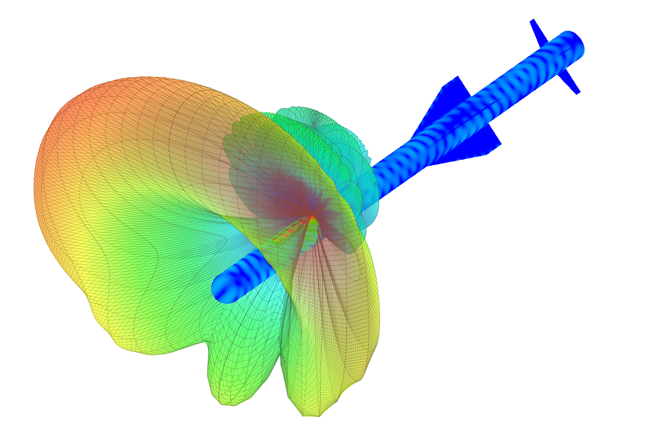
In other words, the proximity fuse's sensitivity cone determines WHEN and WHERE the missile will deposit its fragments.
Here is a great article on how a SAM proximity fuse sensitivity cone is achieved :
https://www.feko.info/applications/...-fuse-antenna-for-an-air-defence-missile/view
This guy uses a linear microstrip antenna array at 2.4 GHz, but similar sensitivity cones can be achieved with 80's technology at lower frequency and with coil antennas.
I'm not sure if I make myself clear here, but the important part is that the entire system is tuned so that the warhead fragments will hit the location where the proximity fuse sensitivity cone first detects enough metal within the "kill range" distance from the missile path. Which is a RING around the missile path the size of the kill range, and NOT strait ahead.
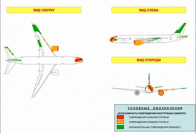
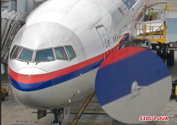
In the case of the Snizhne approach, that first metal detected was almost certainly (a meter or so into) the nose of MH17, and the warhead indeed delivered the bulk of fragments right at that location.
But in the case of the Zaroshens'kye approach, the first metal that the proximity fuse would have detected would be some part of the right side of the plane, behind the cockpit, in which case it would have blasted that area with fragments.
And that obviously did not happen, so either the launch was not from the Zaroshens'kye direction, or the proximity fuse seriously malfunctioned.

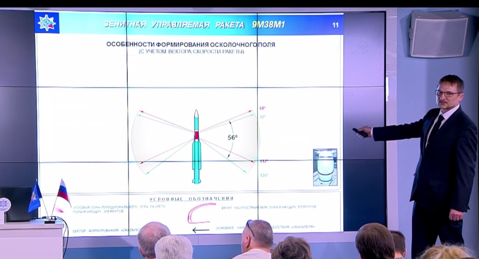
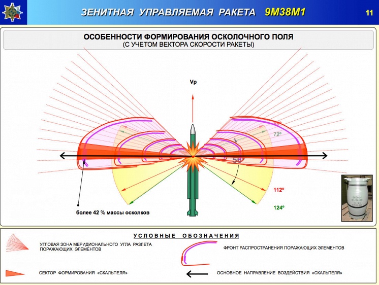
") If you don't account for the speed then you don't know where the fragments go.
If you don't account for the speed then you don't know where the fragments go.