
You are using an out of date browser. It may not display this or other websites correctly.
You should upgrade or use an alternative browser.
You should upgrade or use an alternative browser.
The Shape and Size of Glare Around Bright Lights or IR Heat Sources
It's unpolished. But I've got a polisher, and it will be interesting to see how well it works without polishing. I was quite surprised what a good image you get reflected from a matt metal surface, so maybe a window might work somewhat with not polishing.20mm, 2mm thick, for 20 bucks. Not bad! Be careful with them, is my advice. If you drop em, they crack.
Here's a metal surface reflecting my hand in thermal IR.
But, it's matt, with near-zero specular reflectivity.
Attachments
When looking at jet engines in IR, another factor besides glare comes into play.
The elongated hot exhaust plume itself is a source of IR radiation as well. So the black (or white) blob that you see when looking directly at the back of the jet will also be caused by the exhaust plume, which is a rather thick cloud of hot gas from that line of sight (looking directly into the end of the exhaust plume). The IR image from that hot gas will of course not rotate in the gimbal case.
The images showing rotating glare in IR and visible light can be a bit misleading in that sense, since they only show glare.
The images demonstrating glare from jet engines do show the typical spikes radiating out, which indeed do rotate with the optics, but the center of the blob does not since it is a thermal image of something physical (a hot exhaust cloud), not glare.
Can you show an example of what you mean?The images demonstrating glare from jet engines do show the typical spikes radiating out, which indeed do rotate with the optics, but the center of the blob does not since it is a thermal image of something physical (a hot exhaust cloud), not glare.
There were some questions related to exposure and contrast in this thread so I thought I'd look into what the ATFLIR in particular might be capable of in that regard.
ATFLIR related patents refer to the "time of each exposure, typically measured in milliseconds", but there's no mention of exposure in this ATFLIR technical manual, only gain and level settings. The manual says:
Both exposure and gain/level could increase the brightness of the image but for example this document about selecting IR cameras says that there are pros and cons, that "the shorter the exposure time, the less likely there will be blurring for high-speed events" and that "some cameras have better thermal resolution and are therefore more sensitive. We can deduce that it requires less exposure time for the higher-sensitivity cameras to get the same image", where thermal resolution is defined as the "smallest temperature change the IR camera can detect above its noise floor" and for example this presentation mentions that increasing the gain also amplifies the noise. We don't know what the thermal resolution is for the ATFLIR. This article says that cameras "with a cryocooler ... can result in significantly improved thermal sensitivity". This paper says "Cooling air is provided to the ATFLIR by the F/A-18", and the manual also mentions the "aircraft cooling air for the components of the ATFLIR pod". We can see a comparison of cooled and uncooled cameras here. These points provide a potential reason for why they might've chosen to use a low fixed exposure time, to keep motion blur low and perhaps a high enough sensitivity might've allowing them to only vary the gain, but it's very inconclusive.
Among others here, some VFX artists analyzing Gimbal also made the point that explosions in IR show changes in the effective dynamic range of the image. Many such explosions imaged with ATFLIR can be found by looking up VFA cruise videos. The following are just a few examples of what it looks like for the first frame or two of the explosion, and what it looks like after the camera immediately changes exposure/gain after that, with the background appearing to become much colder.
From here:


From here:


From here:


It appears that some information about the background from before the explosion is lost with a huge glare suddenly covering it, and then as the camera changes settings the size of the glare is drastically reduced and some of that background information becomes visible once again. But as the camera internally uses 14 bit values containing more information than just the 8 bit output we see, and if gain is an analog effect that could create some contrast where a purely digital effect couldn't, could these effects be due to just gain/level changes, or are exposure changes required for them ?
People have noticed that the clouds in Gimbal appear to have some contrast with some hotter regions which seem unusual given how cold the scene is supposed to be at that altitude, at night, with the clouds below blocking any radiation from the ground, and that this could be indicative of the thermal range being narrow in the image, perhaps because for example the gain (contrast) setting is higher than usual ?
ATFLIR related patents refer to the "time of each exposure, typically measured in milliseconds", but there's no mention of exposure in this ATFLIR technical manual, only gain and level settings. The manual says:
According to an article about the "Basics of Digital Camera Settings"The digital non-uniformity correction (DNUC) channels pixel-to-pixel non-uniformity and converts the analog signal to digital. The low-noise 14-bit DNUC receives the ATFLIR detector video output and applies level and gain corrections to each pixel. A fine level calibration takes less than one second.
...
Level is adjusted from 0 (least brightness) to 9 (highest brightness)
...
Gain is adjusted from 0 (least contrast) to 9 (highest contrast).
...
ALG pushbutton switch: ... When boxed, selects automatic level and gain controlled by the FLIR pod
The ATFLIR manual doesn't say which type of gain the pod uses, but as the gain is applied by the unit that converts analog to digital, and as it is intended to increase the contrast, it is most likely real gain. Still there's a question of whether the exposure time in ATFLIR is fixed and there's only the "automatic level and gain" algorithm that the manual mentions or if there's some undocumented auto exposure algorithm in addition to that.Gain can be before or after the analog-to-digital converter (ADC). However, it is important to note that gain after the ADC is not true gain, but rather digital gain. Digital gain uses a look up table to map the digital values to other values, losing some information in the process. ...
In general, gain should be used only after optimizing the exposure setting, and then only after exposure time is set to its maximum for a given frame rate.
Both exposure and gain/level could increase the brightness of the image but for example this document about selecting IR cameras says that there are pros and cons, that "the shorter the exposure time, the less likely there will be blurring for high-speed events" and that "some cameras have better thermal resolution and are therefore more sensitive. We can deduce that it requires less exposure time for the higher-sensitivity cameras to get the same image", where thermal resolution is defined as the "smallest temperature change the IR camera can detect above its noise floor" and for example this presentation mentions that increasing the gain also amplifies the noise. We don't know what the thermal resolution is for the ATFLIR. This article says that cameras "with a cryocooler ... can result in significantly improved thermal sensitivity". This paper says "Cooling air is provided to the ATFLIR by the F/A-18", and the manual also mentions the "aircraft cooling air for the components of the ATFLIR pod". We can see a comparison of cooled and uncooled cameras here. These points provide a potential reason for why they might've chosen to use a low fixed exposure time, to keep motion blur low and perhaps a high enough sensitivity might've allowing them to only vary the gain, but it's very inconclusive.
Among others here, some VFX artists analyzing Gimbal also made the point that explosions in IR show changes in the effective dynamic range of the image. Many such explosions imaged with ATFLIR can be found by looking up VFA cruise videos. The following are just a few examples of what it looks like for the first frame or two of the explosion, and what it looks like after the camera immediately changes exposure/gain after that, with the background appearing to become much colder.
From here:
From here:
From here:
It appears that some information about the background from before the explosion is lost with a huge glare suddenly covering it, and then as the camera changes settings the size of the glare is drastically reduced and some of that background information becomes visible once again. But as the camera internally uses 14 bit values containing more information than just the 8 bit output we see, and if gain is an analog effect that could create some contrast where a purely digital effect couldn't, could these effects be due to just gain/level changes, or are exposure changes required for them ?
People have noticed that the clouds in Gimbal appear to have some contrast with some hotter regions which seem unusual given how cold the scene is supposed to be at that altitude, at night, with the clouds below blocking any radiation from the ground, and that this could be indicative of the thermal range being narrow in the image, perhaps because for example the gain (contrast) setting is higher than usual ?
Last edited:
A video exploring the relationship between tail angle and glare size.
Source: https://www.youtube.com/watch?v=60jz6xc26zg
Basically, it's not a narrow beam, and it's not collimated, so you can be off-axis for 30+ degrees (flashlight or jet engine) and the size of the glare will not vary with the angle.
Source: https://www.youtube.com/watch?v=60jz6xc26zg
Basically, it's not a narrow beam, and it's not collimated, so you can be off-axis for 30+ degrees (flashlight or jet engine) and the size of the glare will not vary with the angle.
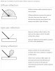
This report "Aircraft Infrared Principles, Signatures, Threats, and Countermeasures" (2012) (attached) was shared on Twitter by @TheCholla, and it's got a lot of interesting stuff in it about whay planes look like in infrared, and why. @TheCholla noted that it does not discuss glare. Itis somewhat limited by classification, and does not discuss the specifics of current technology.

This is just a rough schematic, but shows that the Hot Parts dominate for a significant angle (roughly +/- 20° in this particular diagram)
That said, still of interest, and related to the above video, where I'm demonstrating glare from the "hot parts" that you see when roughly tail-on. The paper breaks down sources of IR into four components, and this diagram roughly illustrate what components are important at various viewing nagles.
Details of military IR technology, missiles, and countermeasure systems arenecessarily classified, and the EW courses at NAWCWD Point Mugu are taught at thatlevel. This report is unclassified for distribution to a larger audience than is able to attend the courses. This report being unclassified limits the material included to general principles and the figures provided to drawings and photographs that have been released to the public domain. The IR images used are of F-4 and F-14 aircraft that are no longer operational in the United States.
This is just a rough schematic, but shows that the Hot Parts dominate for a significant angle (roughly +/- 20° in this particular diagram)
Attachments
TheCholla
Active Member
A similar garage experiment but with a turbine engine and IR sensors. More relevant than a lamp torch blinding a regular camera.
https://www.mdpi.com/1424-8220/18/2/428
MWIR (in function of aspect angle)

Radiation area(left) and radiance (right) in the different IR bands (still in function of aspect angle)


I think the Chilean plane-UFO does not show glare as you define it. I think we see the exhaust plume, or region of hot air mixed by wake turbulence behind an airliner. See paper below for example of how large wake turbulence can be.


This shows up as a blob in IR, but I'd bet that if the camera was rotating, the blob would rotate (i.e., not a glare as you define it with your lamp torch experiments).
See Dave Falch's experiment with a distant plane, and a rotated IR camera (RIP to his back) :
Source: https://youtu.be/JFVgkVj7A1U
I think using a lamp torch to claim Chilean is a glare, to then justify Gimbal is also one, is a poor chain of arguments.
https://www.mdpi.com/1424-8220/18/2/428
MWIR (in function of aspect angle)
Radiation area(left) and radiance (right) in the different IR bands (still in function of aspect angle)
I think the Chilean plane-UFO does not show glare as you define it. I think we see the exhaust plume, or region of hot air mixed by wake turbulence behind an airliner. See paper below for example of how large wake turbulence can be.
This shows up as a blob in IR, but I'd bet that if the camera was rotating, the blob would rotate (i.e., not a glare as you define it with your lamp torch experiments).
See Dave Falch's experiment with a distant plane, and a rotated IR camera (RIP to his back) :
Source: https://youtu.be/JFVgkVj7A1U
I think using a lamp torch to claim Chilean is a glare, to then justify Gimbal is also one, is a poor chain of arguments.
Now do it with correctly exposed high contrast clouds and sky as a background.A similar garage experiment but with a turbine engine and IR sensors. More relevant than a lamp torch blinding a regular camera.
https://www.mdpi.com/1424-8220/18/2/428
MWIR (in function of aspect angle)
TheCholla
Active Member
You can contact these guys and ask them to do another study. I don't have an engine turbine and IR cameras in my garage. And it's your job to prove your theory, not other's to do it for you!
Chilean UFO shows a IR signature you expect from a distant airliner. Reducing in size with distance, showing the two pairs of engines when more tail-on. Very similar to Dave's example above. Gimbal is a complete different story.
None of them are comparable to the huge glare/diffraction spike from the lamp torch.
I think the Chilean plane-UFO does not show glare as you define it. I think we see the exhaust plume, or region of hot air mixed by wake turbulence behind an airliner. See paper below for example of how large wake turbulence can be.
This shows up as a blob in IR, but I'd bet that if the camera was rotating, the blob would rotate (i.e., not a glare as you define it with your lamp torch experiments).
Wake tubulence is not hot. If you can see a contrail, you're not seeing hot air. Exhaust/Contrail mixing with ambient air happens VERY rapidly. It's also not lined up with the camera:
When wake turbulence is wide like that it's a LONG way behind the plane, and at ambient temperatures.
How is it different? An F/A-18's engines fit inside one of the A340's engines, and the entire plane is well within a single engine's glare.Gimbal is a complete different story.
But two F/A-18 engines will be a lot hotter than one A340 engine.
It was a rhetorical suggestion. The point is that here they have exposed for the exhaust. In Gimbal it's exposed for the narrow range of temperatures in very cold clouds. An ideal setting for large glare - similar to the Chilean case where even clouds and contrails are black.You can contact these guys and ask them to do another study. I don't have an engine turbine and IR cameras in my garage. And it's your job to prove your theory, not other's to disprove it!
The gap between an engine and the start of a contrail is the gap between ~600°C and -40°C.The figure I posted is for jet regime (close to the engines).

There’s no billowing cloud of hot air. There’s a small cone of hot gas, then, almost instantly, cold invisible air.
Mendel
Senior Member.
Generally, a high-bypass engine (A340) will be hotter than a conventional jet engine, but the F/A-18 exceeds that when it uses its afterburners.But two F/A-18 engines will be a lot hotter than one A340 engine.
TheCholla
Active Member
Some new footage of fighter jets in infrared, 5-10 miles, taking a turn.
Source: https://twitter.com/DaveFalch/status/1690128011125743616?s=20
Source: https://twitter.com/DaveFalch/status/1690569445251366912?s=20
Pretty consistent with this.

Source: https://twitter.com/DaveFalch/status/1690128011125743616?s=20
Source: https://twitter.com/DaveFalch/status/1690569445251366912?s=20
Pretty consistent with this.
Not super relevant to the 30NM hypothesis.Some new footage of fighter jets in infrared, 5-10 miles
But wouldn't the 6-8NM non-glare hypothesis be invalidated if this was your expectation? Or are you also positing some weird energy field distorting the shape?
jarlrmai
Senior Member.
Can you explain what you mean by this phrasing?good to take
Mendel
Senior Member.
Some new footage of fighter jets in infrared, 5-10 miles, taking a turn.
Source: https://twitter.com/DaveFalch/status/1690128011125743616?s=20
Source: https://twitter.com/DaveFalch/status/1690128011125743616?s=20
Super nice, looks like GIMBAL, note what happens near 20s when they change the exposure: it directly affects the size of the glare, and even at this short distance can obscure the aircraft completely.
TheCholla
Active Member
It's good to have more footages of planes in IR, to discuss how planes look in IR.Can you explain what you mean by this phrasing?
TheCholla
Active Member
That's when the camera refocuses. I don't think it looks like Gimbal at all, more like a jet exhaust seen from the rear then side (see experiment posted above).Super nice, looks like GIMBAL, note what happens near 20s when they change the exposure: it directly affects the size of the glare, and even at this short distance can obscure the aircraft completely.
But I'm out this discussion already, just thought people may be interested in footage/experiments of jet exhausts in IR.
AmberRobot
Senior Member
The refocus looks to be at 20 seconds, whereas there's a definite change in contrast at 18 seconds, where the sky looks darker and the size of the glare around the exhaust gets larger.That's when the camera refocuses. I don't think it looks like Gimbal at all, more like a jet exhaust seen from the rear then side (see experiment posted above).
But I'm out this discussion already, just thought people may be interested in footage/experiments of jet exhausts in IR.
Note that it looks like the engine exhaust is saturating the detector most of the time, so a change in exposure or gain settings could definitely impact the size of the glare.
This is a to-scale overlay of a possible 32NM F/A-18 trajectory with the Gimbal video.
One interesting thing that occured to me when watching it is that the orientation of the jet might explain the asymmetry of the glare - especially earlier in the video. Specifically the direction in which the engines are pointing has a larger glare, which might be from the exhaust plume.
Or it could just be coincidence. Interesting though
Mendel
Senior Member.
Yes, but if that is true, the jet has to rotate with the glare later, doesn't it?One interesting thing that occured to me when watching it is that the orientation of the jet might explain the asymmetry of the glare - especially earlier in the video. Specifically the direction in which the engines are pointing has a larger glare, which might be from the exhaust plume.
No, the glare just has to be a bit bigger in that direction. There's two components to the shape of a glare:Yes, but if that is true, the jet has to rotate with the glare later, doesn't it?
1) The non-glaring thermal signature of the plane and its exhaust, which does not rotate with the gimbal traveral.
2) The glare, which does.
If #1 is only contributing slightly (i.e. at long distances), then it would just make #2 glare in that direction.
When #1 is dominant, like in the close examples that Marik often shares, then any rotation is physical. (i.e. the target rotating, or the camera plane banking)
I want to make an accurate comparison between Gimbal and Chilean using Sitrec. We know Gimbal's FOV is 0.35 square, so 0.35° HFOV and VFOV. The following is just me getting my ducks in a row....
The Chilean segments of interest are with the focal length at 675 (upper right)

What's the FOV? Tom Churchill, an expert user of Wescam FLIRs says:
and
The 1920/1280 comes from displaying the image in its native 1080p (1920x1080). The width of the active portion is 1280 pixels, and the height seems to be 1000 px. So a HFOV of 1.0849 would give a VFOV of 1.0849 * 1000 / 1280 = 0.848° for the active part.
Sitrec uses VFOV. i.e. the FOV you put in to "Plane Camera FOV" is the vertical FOV. For this to be accurate in Sitrec, the aspect ratios need to match, and the VFOV needs to cover the same amount. Since we are covering the full height (1080px, not 1000 px) in the rendered view, the VFOF for our rendering windowis slightly bigger at 1.0849 * 1080 / 1280 = 0.915° (for the 675 focal length).
However, when I do this it results in something that appears exactly twice the FOV suggested by the glare shapes (so the plane is half size)

If I manually double the plane, we get what looks like a perfect fit.

So something is incorrect. Maybe the FOV, maybe my model, maybe something else. I'll figure it out.
The Chilean case was well before Sitrec, so I never got to this level of detail back then, but I'm trying to make Sitrec be more accessible to other people, so it's very important that it's accurate.
The Chilean segments of interest are with the focal length at 675 (upper right)
What's the FOV? Tom Churchill, an expert user of Wescam FLIRs says:
The HFOV we care about in this video is for the MWIR camera. From previous data we have collected, an IR focal length of 675 = 1.0849 degrees (for the active portion of video) For the entire width of the screen (including the black bars to the left and right), it would be 1.0849 degree * (1920/1280) = 1.62735 degrees HFOV. Because this is essentially a prime lens, the accuracy of the reported field of view is generally quite high and consistent across cameras.
and
The FOVs quoted by Wescam in their datasheet are for the active portion of the video. That is, the 675mm focal length (which corresponds to what Wescam calls "1.1 degrees") means an angular field of view from the left side of the sensor image (not including the black bar) to the right side of the inset image. The HFOV of the entire image (including the black bars with no video) would be 1.1 * (1920/1280) = 1.65 degrees.
The fields of view they report for their EOW (Electro-Optical Wide) sensor are for the full frame width.
The 1920/1280 comes from displaying the image in its native 1080p (1920x1080). The width of the active portion is 1280 pixels, and the height seems to be 1000 px. So a HFOV of 1.0849 would give a VFOV of 1.0849 * 1000 / 1280 = 0.848° for the active part.
Sitrec uses VFOV. i.e. the FOV you put in to "Plane Camera FOV" is the vertical FOV. For this to be accurate in Sitrec, the aspect ratios need to match, and the VFOV needs to cover the same amount. Since we are covering the full height (1080px, not 1000 px) in the rendered view, the VFOF for our rendering windowis slightly bigger at 1.0849 * 1080 / 1280 = 0.915° (for the 675 focal length).
However, when I do this it results in something that appears exactly twice the FOV suggested by the glare shapes (so the plane is half size)
If I manually double the plane, we get what looks like a perfect fit.
So something is incorrect. Maybe the FOV, maybe my model, maybe something else. I'll figure it out.
The Chilean case was well before Sitrec, so I never got to this level of detail back then, but I'm trying to make Sitrec be more accessible to other people, so it's very important that it's accurate.
Well, turns out my A340 model is displaying at half size. The sphere here has a diameter of 208 feet, the A340-600 wingspan. Which means that the FOV calculations are likely correct. I just need to figure out where in the pipeline my model scaling has fubared.
Agent K
Senior Member
It usually talks about veiling glare and sensor blooming.Have you found any literature about aviation/infrared mentioning "glare"? I looked over a few papers about exhaust plumes etc... it seems it's an unknown term in that field.
Article: Discrimination between electronic and optical blooming in an InSb focal-plane array under high-intensity excitation
The blooming of IR FPA’s by high-intensity thermal or laser sources is a significant problem in military IR imaging systems. In order to understand how to mitigate such blooming, we have attempted to understand the nature of the blooming phenomena by performing experiments exposing a 640 × 480 InSb FPA to high-irradiance that significantly degraded image quality. These experiments showed that stray radiation produced in the optics is the dominant contributor to the blooming effects.
AmberRobot
Senior Member
I will concede that my understanding of the word blooming was incorrect and it is used for optical effects as well.
Mendel
Senior Member.
After this discussion, my understanding is that glare and bloom are similar effects, caused by dispersion of strong light sources. Bloom encompasses in-camera phenomena (sensor/film and optics), glare indicates phenomena outside the camera (usually atmospheric).I will concede that my understanding of the word blooming was incorrect and it is used for optical effects as well.
Other in-camera artefacts include diffraction spikes, bokeh, and lens flares.
AmberRobot
Senior Member
Having worked with optical imaging and spectroscopic systems for many years, I have a lot of experience with all these effects. But, having been isolated to a specific scientific field, I am used to a particular set of terminology that isn’t necessarily universally used.After this discussion, my understanding is that glare and bloom are similar effects, caused by dispersion of strong light sources. Bloom encompasses in-camera phenomena (sensor/film and optics), glare indicates phenomena outside the camera (usually atmospheric).
Other in-camera artefacts include diffraction spikes, bokeh, and lens flares.
FatPhil
Senior Member.
Were you thinking "bleed" not "bloom"? In the digital sensor domain, such bloom is literally charge bleeding out of one cell into neighbouring ones.I will concede that my understanding of the word blooming was incorrect and it is used for optical effects as well.
Much of the "bloom" in the optics domain I tend to consider just a soft focus effect, whether by engineering design or not.
So all in all, I think I was with you on the interpretation of "bloom"
As different people from different backgrounds start to overlap fields, terminology can certainly become wierded. Just consider yourself lucky that tonightt you won't utter the phrase "a half-litre plastic pint glass", which is absolutely a thing now in some parts of the world.
AmberRobot
Senior Member
It seems that "bloom" is a general term regarding an effect and there are multiple potential causes for that effect, including both those of the optics (e.g., stray light) and those of the sensor (e.g., charge bleed).Were you thinking "bleed" not "bloom"? In the digital sensor domain, such bloom is literally charge bleeding out of one cell into neighbouring ones.
Much of the "bloom" in the optics domain I tend to consider just a soft focus effect, whether by engineering design or not.
So all in all, I think I was with you on the interpretation of "bloom"
As different people from different backgrounds start to overlap fields, terminology can certainly become wierded. Just consider yourself lucky that tonightt you won't utter the phrase "a half-litre plastic pint glass", which is absolutely a thing now in some parts of the world.
It is not a term I have personally used in any technical capacity.
After this discussion, my understanding is that glare and bloom are similar effects, caused by dispersion of strong light sources. Bloom encompasses in-camera phenomena (sensor/film and optics), glare indicates phenomena outside the camera (usually atmospheric).
Other in-camera artefacts include diffraction spikes, bokeh, and lens flares.
When I refer to glare, I'm referring to an in-camera effect, but not bloom. Unfortunately the terminology here is not consistent, but I use "glare" because the type of stray light we refer to is discussed in the literature as having a "glare-spread function".
I probably should have just invented a new term.,
Similar threads
- Replies
- 10
- Views
- 2K
- Replies
- 43
- Views
- 7K
- Replies
- 4
- Views
- 1K
- Replies
- 8
- Views
- 2K