Questions about knifed connection and erection clearance

taha

New Member
1) what is knifed connection?
2) what is erection clearance?
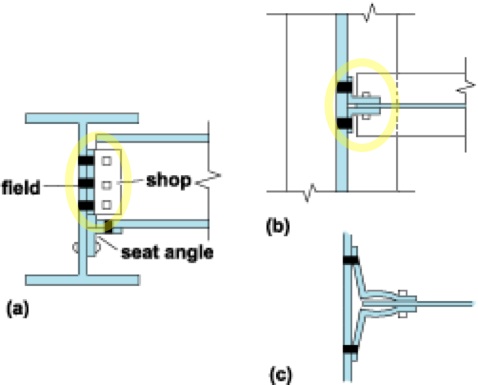
3) in aisc manual , chap 10 page 10 it is written in the second line, if both angles are shopped attached to the beam web, the beam length can be shortened to provide for mill over run with shims furnished at the appropriate interval to fill the resulting gaps or to provide mill under run.
can you please explain in easy works with a little detail so i can understand the whole phenomenon, and i will be thankful if you will tell me the meaning of the next sentence after this.
 
Last edited by a moderator:
1) A knife connection is where part of a girder (the "knife") goes between two angled metal plates ("knife plates") which are bolted or welded to the column (or beam).


2) the "erection clearance" is a gap that allows you to erect (put together) a connection. If measurements are too exact (designed so everything fits with no gap) then it can be impossible to get things into the right position.

3) This means that if the angles (e.g. the knife plates) are pre-attached to the beam (attached in the shop) they you should specify (ask for) the beam a bit (a few mm at most) shorter than you need it (give it some extra erection clearance) in case the shop overruns (makes it too long). Then if it ends up too short you can use a shim (thin metal plate, also called a "pack" or "shim pack") to make it longer. The shim would go between the knife plate and the column.

Why do you ask?
 
Last edited:
Related to the above, the connection to column 79 in WTC7 were not knifed, and we just bolted to the seat plate and clip angle.


This is because they were not moment resisting connections - they did not have to resist any twisting force (moment) from wind loads, as they were interior connections and the exterior of the building was a moment frame.

In earthquake regions, interior connections like this would be moment connections. If it was a moment connection, then WTC7 probably would not have collapse (like the Interstate Bank in Los Angeles didn't), or at least not as quickly.
 
Last edited:
thank you so much, i find this forum very helpful,
actually i am working on steel structure for my final year project at university, i talked with the head of a firm which is purely design office.
so they said me to go through to AISC and seismic manual . so i need to things to be clear. the project we have taken for final year project is the most hardest and difficult in the university. we are designing the steel structures of a power plant. and in university , we have only started steel subject 6 months before so i i know about 2 or less than 2 percent about the subject of what we are going to do.. we have finished 10 chapters of aisc manual. not methods . but the phenomenon and theories, so we will go to the head of the design office and we will start work on the real project.

You are welcome. This is just a debunking site though, not really structural engineering. That is just incidental to debunking (explaining what is incorrect with) the 9/11 World Trade Center collapse theories. With respect, it seems like your questions are based on English not being your native language.
 
You are welcome. This is just a debunking site though, not really structural engineering. That is just incidental to debunking (explaining what is incorrect with) the 9/11 World Trade Center collapse theories. With respect, it seems like your questions are based on English not being your native language.
english is my second language,
are you asking me to tell the reasons of the failing of WTC? or just telling that this site is for the discussion of the reasons of a falling or collapsing structures?
sorry i did not get it.
 
shear plates are in yellow color in the above diagram ? i mean i have read that they are stiffeners? correct me if i am wrong.
 
english is my second language,
are you asking me to tell the reasons of the failing of WTC? or just telling that this site is for the discussion of the reasons of a falling or collapsing structures?
sorry i did not get it.

I am telling you that this site is for the discussion of debunking. That is scientific skepticism. شكوكية علمية

It it not a problem that you are here. It is an an interesting topic.
 
shear plates are in yellow color in the above diagram ? i mean i have read that they are stiffeners? correct me if i am wrong.

No, it's the blue end plate. It's a shear connection at the end of a beam. But "end shear plate" is not really a common term.

The yellow plates (transverse web stiffeners) stiffen the girder locally. The blue plate is creating (to a degree) a moment resisting connection and it stiffens the entire structure.
 
Out of interest I was just reading AISC, and it defines a shear end-plate as having a plate length less than the supported beam depth. So the diagram above does not show that, the blue plate is actually an "extended end plate" or a "bolted moment end plate". Here's a better example of a simple shear end plate (the orange):


This slide show gives very good examples of the different connections:
http://www.slideshare.net/nadimnit/bracing-connections

And this is a good list:
http://www.steel-connections.com/lmc_types.htm
 
Last edited:
NCSTAR_1-9_WTC7_unlocked.pdf_(SECURED)-20130505-122313.png
this diagram shows that seat is welded on supporting beam (horizontally), but other diagram shows them similar to angle. i have doubt in it.
 
Not all shear end plate connections have a seat.

Some are just simply shear connections.

Some seated connection have no end plate, just the top and bottom bolts.
 
NCSTAR_1-9_WTC7_unlocked.pdf_(SECURED)-20130505-122313.png
this diagram shows that seat is welded on supporting beam (horizontally), but other diagram shows them similar to angle. i have doubt in it.

There are really two different connections shown there. The front and side projections have the beam at right angles. The section (top projection) does not.
 
i mean.. the seat is welded to the web of the supporting beam, as shown in the figure above, on the very left side, at the top flange it is joined with clip angle, at bottom flange , bolts are fastened with seat, which is welded to the web of the supporting beam, and below the seat there is a plate.
but as shown in this photo
http://image.slidesharecdn.com/brac...72841-phpapp01/95/slide-14-728.jpg?1298676767
it looks like a clip angle.
i am little confused abut the components of connections and all tat stuff, i do not find a clear diagram which point all the components.
i studied 9 hours continusly yesterday searching and reading but still i am not clear in all the aspects.
 
Back
Top