Sgt.Squarehead
Member
I'd imagine that rather depends on whether it's trying to kill you or not!(Also it could be a Su-33 but it doesn't matter)
")
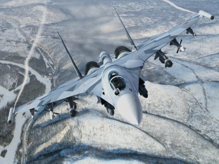
Know your Flankers:
https://www.milavia.net/aircraft/su-27/su-27_variants.htm
Last edited:

I'd imagine that rather depends on whether it's trying to kill you or not!(Also it could be a Su-33 but it doesn't matter)
Here's a cheat sheet on page 9 of the PDF file.Ah, that makes sense. It's MidIR, so an InSb (indium-antimonide) array. I've never use one, but, AFAIK, blooming can happen in an InSb focal plane array. Here's a paper about it, with figures, but it's behind a paywall. Maybe someone can find a better source.
Discrimination between electronic and optical blooming in an InSb focal-plane array under high-intensity excitation.
The Chilean UFO is not defined.
You can see two distinct heat sources flickering with poorly defined edges. What you would expect looking at the exhaust of a jet engine (airliners have engines wide apart). What you are seeing in the Chilean video is not just "glare". It's simply the hot gases pointing directly towards the camera. That is why they are not a solid shape. They flicker as the gasses diffuse in the atmosphere.
Just like this video shows clearly:
Source: https://twitter.com/DaveFalch/status/1278856646954029057
Gimbal does not flicker. The edges are solid and not undefined. It doesn't look like a jet exhaust.
It could be glare from a solid powerful IR source (e.g. not a flare burning as it would flicker but a hot space capsule reentering? or an IR laser pointing at the camera?).
I disagree with that logic. You're basically saying "all smudges are small". I cite as a counter-example ... a large smudge smeared across the whole of the front of the optics. Who could possibly have seen that coming?!
I disagree with that logic. You're basically saying "all smudges are small". I cite as a counter-example ... a large smudge smeared across the whole of the front of the optics. Who could possibly have seen that coming?!
The scattering must be (1) very consistent and (2) very concentrated to cause a delineated black image saturation spot like that.Yes. So if a smudge only scatters light a little (I.e., into a small cone) it will create an enhancement around every bright object in the field. The clouds already have fuzzy edges and are not nearly as bright as the main object so you don't see the enhanced scatter. The main object is bright, probably saturating at the center, so it's easier to see the impact of the mild scattering. Much the same way that a telescope with a secondary spider will show diffraction spikes around bright stars but not around dimmer, extended objects like planets or nebulae.
A smudge on the window cannot cause these kind of effects, it will never be as symmetrical and consistent.
That's only partly the case; the first rotations come a bit earlier.and yet the effect rotates at exactly the moment you might expect the gimbal to rotate and when other artifacts in the scene rotate. It's definitely suspicious.
That's only partly the case; the first rotations come a bit earlier.
The background veiling glare that rotates with the object is not that remarkable, you would expect this to happen, too, if a bright object outside rotates. It could simply be veiling glare caused by the normal dirt that accumulates on the ATFLIR front window.
The object does rotate most when the jet is pointing its nose at it. And then there are these strange jolts in the optics that seem to prelude the object's rotation.
I wonder if these jolts could be caused by triggering the laser range designator (LRD). One would expect a small final fine-tuning of the ATFLIR boresight alignment at that moment. The object rotation could be a response to the laser being pointed at it.
As a pilot I would really like to have a range when I'm flying head-on towards an object of unknown size. If the radar did not give me one I would try the LRD. That could explain the fact that most of the object's rotation takes place when the jet is flying straight towards it.
Googled it:As far as I know the ATLFIR LASER is not used for ranging aerial targets, if it fires there is an indicator showing it fires.
The LASER is for ground target designation and ranging and has a range limit.
Source: https://www.militaryaerospace.com/s...79/electrooptical-infrared-targeting-avionicsExternal Quote:The Raytheon ATFLIR has plug-and-play performance, and integrates advanced visible-light cameras and infrared sensors with a target laser designator to locate and designate targets day or night at ranges exceeding 40 nautical miles and altitudes surpassing 50,000 feet, Raytheon officials say.
Googled it:
Source: https://www.militaryaerospace.com/s...79/electrooptical-infrared-targeting-avionicsExternal Quote:The Raytheon ATFLIR has plug-and-play performance, and integrates advanced visible-light cameras and infrared sensors with a target laser designator to locate and designate targets day or night at ranges exceeding 40 nautical miles and altitudes surpassing 50,000 feet, Raytheon officials say.
Maybe one of the flight simulator users here can explain how it is operated, and whether we should see it on the ATFLIR screen if it is engaged?
Maybe one of the flight simulator users here can explain how it is operated, and whether we should see it on the ATFLIR screen if it is engaged?
I would say that this doesn't mean you can designate targets that are 50,000ft high but instead means you can designate ground targets whilst staying 50,000ft in the air above them.The Raytheon ATFLIR has plug-and-play performance, and integrates advanced visible-light cameras and infrared sensors with a target laser designator to locate and designate targets day or night at ranges exceeding 40 nautical miles and altitudes surpassing 50,000 feet, Raytheon officials say.
The 1-micron tactical laser target designator is blinding, but the 1.55 micron training laser is eyesafe. The laser marker is used as a laser pointer to mark a target for other targeting pods to pick up with their laser spot tracker. I'm not aware if ATFLIR uses the eyesafe laser for air-to-air ranging.As far as I know the laser is never used in air-to-air modes, and never pointed at something the operator doesn't want to kill. Imagine a soldier pointing the laser on his rifle at civilians in order to find out how far away they are.
That's how I interpreted it. A fighter jet can designate ground targets from its maximum altitude.I would say that this doesn't mean you can designate targets that are 50,000ft high but instead means you can designate ground targets whilst staying 50,000ft in the air above them.
I always assumed the range in the Gofast video was measured with a laser. But maybe that's a radar range then?The 1-micron tactical laser target designator is blinding, but the 1.55 micron training laser is eyesafe. The laser marker is used as a laser pointer to mark a target for other targeting pods to pick up with their laser spot tracker. I'm not aware if ATFLIR uses the eyesafe laser for air-to-air ranging.
I always assumed the range in the Gofast video was measured with a laser. But maybe that's a radar range then?
Thanks. Lots of speculation but unfortunately no real answers. Flight simulators will only get you so far (otherwise it would be fairly easy for others to find the weak spots in US air defence), and the rest remains guesswork.There's a whole thread dedicated to the range in Go Fast.
https://www.metabunk.org/threads/atflir-and-range-information-radar-laser-passive-range.11809/
From an engineering viewpoint, it would be very hard to align a nose-mounted radar and a wing-mounted, detachable ATFLIR to one degree accuracy. It would be even harder if you want to be able to mount an ATFLIR under different jets.External Quote:Raytheon's Advanced Targeting Forward Looking Infrared pod delivers pinpoint accuracy and reliability for air-to-air and air-to-ground mission support.
Thanks. Lots of speculation but unfortunately no real answers. Flight simulators will only get you so far (otherwise it would be fairly easy for others to find the weak spots in US air defence), and the rest remains guesswork.
According to Raytheon's website,
From an engineering viewpoint, it would be very hard to align a nose-mounted radar and a wing-mounted, detachable ATFLIR to one degree accuracy. It would be even harder if you want to be able to mount an ATFLIR under different jets.External Quote:Raytheon's Advanced Targeting Forward Looking Infrared pod delivers pinpoint accuracy and reliability for air-to-air and air-to-ground mission support.
To reliably get the range to the ATFLIR's boxed target specifically, radar and ATFLIR need to be aligned to 0,1 degree accuracy (the ATFLIR FOV is about 1 degree and a target covers about 10% of the FOV). So given these considerations I guess the LRD is the only device that can reliably tell you the distance to a boxed target since the LRD is fully integrated in the ATFLIR pod with advanced boresight alignment.
What evidence? The manual of a flight simulator? Apart from that I haven't seen much evidence.Um no, RADAR can scan targets in a large area. The sources all say the laser is not used for ranging in air to air, this much is clear, you seem to be disregarding the evidence here.
Meaning: you don't need two air-to-air weapon stations anymore (one for laser tracking and the other for infrared targeting) because we have integrated them both in a single pod.External Quote:The streamlined ATFLIR integrates laser tracking and infrared targeting functions on F/A-18 aircraft into a single compact pod, freeing an air-to-air weapon station for other mission requirements.
The background veiling glare that rotates with the object is not that remarkable, you would expect this to happen, too, if a bright object outside rotates. It could simply be veiling glare caused by the normal dirt that accumulates on the ATFLIR front window.
It seems he is imagining a scenario in which the dirt causes a primarily diffuse scatter, filling all field angles with some fraction of the primary light source, rather than a primarily forward scattering function, which would cause localized glares around bright objects in the field.How would that work?
You seem to be positing that the saucer shape is the shape of the object, a hot object, but not hot enough to create a surrounding glare, but somehow hot enough to create a veiling glare?
This makes no sense.
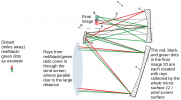
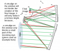
These are the scatter functions of 1 micron (top figure) and 2,5 micron (bottom figure) dust particles for different wavelengths:It seems he is imagining a scenario in which the dirt causes a primarily diffuse scatter, filling all field angles with some fraction of the primary light source, rather than a primarily forward scattering function, which would cause localized glares around bright objects in the field.
on my current project I contracted an optics company to do a scattered light analysis of my instrument'a optical system and they showed me scattering functions as related to cleanliness level, defined as a certain density of small particulates on optical surfaces, and all of the functions were greatly peaked around 0 degrees of scattering deviation.
I'm sure I could be wrong but I still believe that with dust or smudges you would see local glares around the brights objects and possibly additionally some broader scattered light across the field. But if I only saw the broad scattered light without the point glares I would think it's from some kind of stray light source outside the field of view.
but it could be different with large dust particles or smudges than with the small amounts of contaminants my analysis was concerned with.
@Itsme , The graphs you show are related to mie scattering (volume scattering).
I was always using BRDF to look into stray light of optics. (https://en.wikipedia.org/wiki/Bidirectional_reflectance_distribution_function)
With BRDF you can model/predict straylight inside an optical system, as it relates to surfaces (of optics).
If you look below, you see that the "glossy" component (uniform roughness of optics) is distributed more wider, angularly, as opposed to the "specular" distribution (dirt/particles/smudges).
View attachment 45885
source
Dust is very relevant here, see ATFLIR windscreen picture above.You're still assuming isotropy. Smears are highly anisotropic. Highly correlated with the direction of the last wipe of the cloth that cleaned them.
Also, dust clouds are irrelevant here - this is an extremely thin layer, not an extensive diffusive medium.
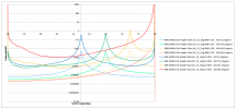
I've attached an image of a series of BSDFs I received from an optical engineer doing a scattered light analysis of an instrument I am working on. There are a few different ones but focus on the higher set, which correspond to what's called CL400, a specific cleanliness level that correlates to a certain particle size distribution (i don't have that at hand). The lower set is from surface roughness of the optics and is negligible in comparison.These are the scatter functions of 1 micron (top figure) and 2,5 micron (bottom figure) dust particles for different wavelengths:
View attachment 45879
View attachment 45880
Source
For a scattering angle from 0 to 1 degree, the FOV of the ATFLIR, the scattering intensity is almost uniform. This means the scattering glare will be evenly distributed over the entire image, not localized around the object.
1 to 2,5 microns is a typical dust article size:
View attachment 45882
Source
The 'R' in BRDF stands for Reflection. We're talking about transmission here, transmission through the ATFLIR windscreen:
I just realized I can make this statement a bit stronger: I only assume there is NO anisotropy in scattered light over the angular size of the object in the Gimbal video. I guess that's in the order of 0,1 degree.Dust is very relevant here, see ATFLIR windscreen picture above.
I'm only assuming near isotropy in the first degree of scattering, because that's the only scattered light that will travel to the imaging electronics via the optics. The (an)isotropy of the rest of the scattered light is irrelevant.
Dust is very relevant here, see ATFLIR windscreen picture above.
I'm only assuming near isotropy in the first degree of scattering, because that's the only scattered light that will travel to the imaging electronics via the optics. The (an)isotropy of the rest of the scattered light is irrelevant.
I've attached an image of a series of BSDFs I received from an optical engineer doing a scattered light analysis of an instrument I am working on. There are a few different ones but focus on the higher set, which correspond to what's called CL400, a specific cleanliness level that correlates to a certain particle size distribution (i don't have that at hand). The lower set is from surface roughness of the optics and is negligible in comparison.
You'll notice a couple of things. These scattering functions are highly specular, especially compared to the functions you posted above. For example, for the blue curve in the middle, angle of incidence is zero degrees, by ten degrees out it is at least an order of magnitude lower than your curves.
I admit that perhaps these curves are not appropriate for this situation but we'd have to figure out what really is. I don't believe that your plots, and even mine, are definitive answers. But I do know the plots I've seen are specifically for examining the impacts of light scattering from optics. It seems your source is for laser scattering through air with particulates, like for measuring pollution.
If my optics had a really bad smudge we'd have to have them cleaned and wouldn't fly with that. We even expect that the CL400 is too high for us, given that most of the optics will be assembled in a clean room.
Of course I can. If the curves broaden with growing wavelength, the part between 0 and 1 degree will be even more homogeneous in mid IR, which only strengthens my arguments.By the way, the plots you show (1 um and 2.5um dust particles) are limited to 850nm. As you can see the curves broaden when going to longer wavelengths. This is what I mentioned before: IR is more prone to straylight and diffraction effects. So you cannot claim anything using the plots provided. BR(S/T)DF has to be used to observe the effect caused by optics+particulates.
You overlook/ignore my next sentence: "So you cannot claim anything using the plots provided. BR(S/T)DF has to be used to observe the effect caused by optics+particulates.Of course I can. If the curves broaden with growing wavelength, the part between 0 and 1 degree will be even more homogeneous in mid IR, which only strengthens my arguments.
So, you seem to think you can fly a jet from an aircraft carrier with a big smudge of non-evaporating (i.e. fatty) fluid on the ATFLIR wind screen without it collecting dust?Wow. Way to misquote. You can't go from "dust clouds are irrelevant - this is an extremely thin layer, not an extensive diffusive medium." to "Dust is very relevant" unless you're literally prepared to just throw away they entire argument of your interlocutor. In which case, goodbye.
"So you cannot claim anything using the plots provided.": Yes I can, see my previous answer.You overlook/ignore my next sentence: "So you cannot claim anything using the plots provided. BR(S/T)DF has to be used to observe the effect caused by optics+particulates.
Source: http://www.graphics.cornell.edu/~westin/multimedia-paper/node7.htmlExternal Quote:It arises from diffraction and scattering by the surface roughness.
No. Show me which sentence gave you that impression.So, you seem to think you can fly a jet from an aircraft carrier with a big smudge of non-evaporating (i.e. fatty) fluid on the ATFLIR wind screen without it collecting dust?