Gimbal distance and Speed Range Estimates using Lines of Bearing and/or DCS

Had a go at getting some examples from the ATFLIR in DCS to try and get an estimate for the size of the UFO, below is a small-ish single engine jet (CASA C-101CC Aviojet) at 10nmi flying directly away at the same altitude and speed. The bottom four are in IR white hot mode with the same FOV, just changing the image settings and it seems that you can get a variety of different looking shapes as well as being able to make the body disappear while the nozzle and reticule bars remain clear (middle left).
It's possible to get something to look similar to the GIMBAL footage although I should stress that the ATFLIR has only recently been added to DCS so still has some bugs and will never be able to perfectly simulate things like glare, smudges on the glass etc. Not sure how close it would need to be for it to be unmistakeably a jet, also not sure on the range that the pilot could identify it by eye as I don't have access to a real F-18.

ATFLIR.jpg

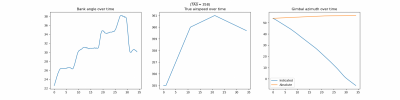
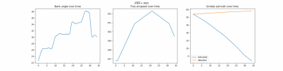
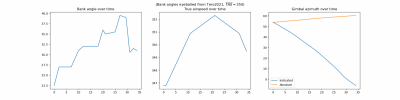
I can't quite get my head around working out the milliradians that Chris mentioned so I found a very rough way to estimate the size just using the ratio of reticule bars to the velocity vector and the range. Considering that the reticule and vector are approximately the same size in the video a good rule of thumb seems to be Range (nmi) = Size (m).

CalculateWingspan.jpg

If the GeoGebra stuff is correct and this way of finding the size is OK, I can't see any reason why a small jet flying away from the f-18 with afterburners and slightly incorrect settings isn't consistent with what we are seeing in the video.
 
In his video Chris draws three lines of bearing, but he also mentions a fourth point that can be extrapolated.

With three points, another line can be drawn that intersects the lines of bearing equidistant apart in several places by changing the angle of the intersecting line. Had he taken the time to extrapolate the fourth point, I think is analysis would have fallen apart. I don't think he would be able draw a line that intersects four lines of bearing equidistant apart at the distance he liked, or perhaps at any distance from the fighter.

1623670297967.png
 
I think you got it without wind shear. Assuming the object is flying at a constant speed and direction, there is a point where the distance between the lines are the same about 13 km to 14 km away. Angle looks about right for the object flying away from the F-18. I don't know the time interval between the lines, so will let someone else figure the objects speed, but looks like it's pretty normal for a jet.

This seems correct. If we put an F-18 around 14-15 miles away flying 240 knots then the numbers on the ATFLIR DDI are basically identical to the original video.


The plane itself is difficult to see and jitters about but I think that is just the sim, it looks maybe a bit small (F-18 has a 12.3m wingspan compared to the 15m you get from my rule of thumb) but that might be the sim failing to model the glare or my dodgy rule of thumb. The important bit is that the bank angle (seen at the bottom), altitude, speed and target pod angle can be matched.

Here is the Tacview:
Screenshot 2021-06-14 133901.jpg

I'm fairly confident that what you see in the video is a jet, around 12m, 15nmi away flying at 250knots, 60deg off of the ATFLIRs original bearing.
It's jittery because you are only SLAVING to the RADAR track, try obtaining an optical auto track after you SLAVE.

For bonus points remove the SLAVE afterward but maintain the autotrack.
 
If we assume the wind speed is constant throughout a volume of air containing both the f-18 and the gimbal object, we can just ignore it. It will affect the ground path of both objects but we don't care about that; we care where one object is in relation to the other. Wind shear (which I defined here as an extra component of wind affecting the motion of the plane only) is potentially important, particularly if we're seeing something tens of nautical miles away. According to wikipedia, wind shear is significant at airliner-like altitudes if it exceeds 45 knots over a short distance. This page suggests short distance is 1 to 4 km. The figure I used of 44 knots is borderline but could be plausible if the distance is large enough.

One thing I notice is that the first two lines are almost parallel, consistent with a distant object. The last two lines are _also_ almost parallel, consistent with a distant object. This seems suggestive that there's some unaccounted for systematic error in the trajectory of the jet. One possibility is the CAS -> TAS conversion. We don't know the altimeter setting that day, so we just punched in 29.92. We don't know the air temperature, so we just used a standard atmosphere. It could make a difference.
Yeah that checks. I played around with changing the turn Radii to simulate wind and it didn't really change the results much. The rate is the most important figure. The temperature is another huge variable. On my model if the TAS is higher it tends to pull the lines apart a bit. Those final two bearings are still a bit odd though. A wind shear and perhaps an unknown speed/heading change of the object could also be throwing things off.
 
It's only just dawned on me that this is what Chris is doing wrong. He flies the plane in DCS to get a turn rate of 2.27 degrees, then goes back to the graph, sees that this gives a wrong result and justifies his result by saying:

Which is complete nonsense

It's true that the a heavier jet requires more lift and thrust to maintain altitude, but the whole point in g-force is that it is independent of mass.

At the same time he mentions that lighter jets are better for dogfights so you might be right that he is getting confused with the potential/kinetic energy stuff for BFM manoeuvres. As I understand it the reason a light aircraft will turn better in BFM is because it can afford to dump speed to tighten the turn as it can quickly build energy again with the better thrust-weight ratio, whereas a heavy aircraft would dump speed, perform the same tight turn and then be a sitting duck.
Yep, you nailed it. He is running the chart for 30 degrees bank but he's doing 40 degrees bank. Running the chart at 30 when he's actually doing 40 is why he must add G forces to make the chart work. I'm guessing he's flying with a keyboard since his pitch and bank is erratic, so the whole demonstration isn't really proving anything.

Yeah, the weight and config certainly factors into aircraft performance in terms of the maximum G's they can sustain, how quickly they can accelerate, thrust to weight ratio etc... None of that is relevant when analyzing level, coordinated, unaccelerated turns.
 
New and improved:


The Auto-track was a bit of a headache, couldn't get it at the first range so had to bring the other jet a bit closer to do it. Don't know if that's user error, the sim or if the real pod wouldn't be able to autotrack an F-18 over 15nmi away (couldn't find any documentation on this but it could be important for the tic-tac FLIR footage if the autotrack has range limitations).
Seems like there is more margin for error than it looks like in GeoGebra, as bringing it 2nmi closer doesn't seem to have a huge effect on the angle of the pod. If I had more patience I'd see how close and how far away I could get it to work as well as different bearings/turning aircraft but I'm happy with this.

That's a really neat demonstration. This plus our Geogebra analyses are very consistent, we are making great progress here ! Now I'd like to understand how a Navy pilot can miss he is tracking another jet only 10-15Nm away.
 
New and improved:


The Auto-track was a bit of a headache, couldn't get it at the first range so had to bring the other jet a bit closer to do it. Don't know if that's user error, the sim or if the real pod wouldn't be able to autotrack an F-18 over 15nmi away (couldn't find any documentation on this but it could be important for the tic-tac FLIR footage if the autotrack has range limitations).
Seems like there is more margin for error than it looks like in GeoGebra, as bringing it 2nmi closer doesn't seem to have a huge effect on the angle of the pod. If I had more patience I'd see how close and how far away I could get it to work as well as different bearings/turning aircraft but I'm happy with this.

As far as I can tell the currently simulated ATFLIR auto track just points the ATFLIR to the object as it "knows" the actual angle so it's not really tracking. It's also not simulating a IR picture, these features are pretty hard to implement in a realistic fashion, you'd have to simulate IR radiation then simulate the FLIR camera pre/post processing filters etc.

The real ATFLIR tracking uses contrast based centroid tracking, so if the object is bigger in IR because of bloom/glare etc then it's actually easier for it to track it at range because it's bigger in IR than in visible light, although you lose any detail on the target at range because the engine IR profile is bigger than the physical object.
 
Last edited:
I'm back! Sorry I had a bunch of articles I had to write over the last few days so I've not been fully keeping up with developments.

I feel like I need to get DCS. Though there's probably a whole learning curve there.

Is it worth doing another video? What should be in it? Or is anyone here planning on doing one?
 
I feel like I need to get DCS. Though there's probably a whole learning curve there.

Yeah, I'm quite new to DCS (only about 100 flight hrs) and prior experience would certainly help although to fly this scenario wouldn't be too difficult for a beginner. I've uploaded the mission planner file if anyone wants a shot, what you would need to do is:

1. Get the F/A-18 ($80!!!) and load the file, you can play around with the positions, speeds etc.
2. Press "t". Click on A/P then BAlt on the centre console. (ATC and Altitude autopilots)
3. Press A/A on the left console to engage Air to Air mode which will automatically bring up the ATFLIR on the LDDI and RADAR on the RDDI.
4. Use ";" "," "." & "/" to get the yellow box on the RDDI over the other plane and press "enter" to lock, the ATFLIR will automatically slave to the target.
5. The rest is then just using the arrow keys (joystick if you have one) to match the bank angle and messing with the settings on the ATFLIR to zoom in on the other plane. (jarlrmai pointed out that pressing "RAlt + ," a couple times will establish an autotrack but this can be temperamental).

Tip: Use "LAlt + z"/"LCtrl + z" to slow/speed up time, in the mission plan I've attached you have about 30/40 seconds to get the autotrack before you need to start the turn to match the original video.

If anyone needs any help or wants me to record something feel free to ask.
 

Attachments

  • GIMBAL Mission Editor.zip
    35.3 KB · Views: 281
If anyone needs any help or wants me to record something feel free to ask.
I'd like to see what the ATFLIR pod actually looks like (from outside the plane) when tracking an object at 2° down from 54°L to 6°R.

i.e. does it do a gimbal correction(s)/roll near 0°? I don't expect it precisely matches the real behavior, but it would be interesting to see how it handles it.

Chris messes around with it, but just rolls the plane and talks about the front-back flip - which is a flip of the image, not the pod itself (same mistake I think Fravor made).

2021-06-15_09-29-11.jpg

I think it will be interesting to see what happens, but relying on the pod simulation to emulate reality to that level should be done carefully.

I'm kind of interested in what blind spots the pod has. Reading around makes me think it's main use is for ground target designation for laser guided bombs. The AA mode must require you to fly in a certain way to give the pod visibility of targets at some aspects. Interesting to see what happens when you ask it to track a target that moves into a blind spot.
 
I'd like to see what the ATFLIR pod actually looks like (from outside the plane) when tracking an object at 2° down from 54°L to 6°R.

i.e. does it do a gimbal correction(s)/roll near 0°? I don't expect it precisely matches the real behavior, but it would be interesting to see how it handles it.

Chris messes around with it, but just rolls the plane and talks about the front-back flip - which is a flip of the image, not the pod itself (same mistake I think Fravor made).

Forgot to do this but in 1x zoom DCS actually shows the entire view from the ATFLIR rotate and I could fly that flight and show that the gimbal does rotate at that point, I have a bit of time to do this later. Not sure how accurate it is to the real thing though.

It's important to note that Chris attached the Litening pod instead of the ATFLIR pod (UI is different) so I'm not sure what that part of the video was about.


Edit: Here it is
 
Last edited:
In his video Chris draws three lines of bearing, but he also mentions a fourth point that can be extrapolated.

With three points, another line can be drawn that intersects the lines of bearing equidistant apart in several places by changing the angle of the intersecting line. Had he taken the time to extrapolate the fourth point, I think is analysis would have fallen apart. I don't think he would be able draw a line that intersects four lines of bearing equidistant apart at the distance he liked, or perhaps at any distance from the fighter.

1623670297967.png


I did my own extrapolation with the 4th point, and this is what I came up with.

1623788173748.png

Using a constant radius turn, the fourth point does not fit the first three at any distance.
 
Last edited:
I'd like to see what the ATFLIR pod actually looks like (from outside the plane) when tracking an object at 2° down from 54°L to 6°R.

Moved the other F-18 down to 22,000ft (again there seems to be quite a big margin of error to get the videos to match) to get -2 degrees and synced up a view of the gimbal mount. My screen recording isn't great resolution but the rotation is pretty convincing.

 
The theoretical assumptions seem plausible to me, and they would apply here provided we're happy to assume the object is flying straight and level at constant speed. However, it only works with a fairly accurate estimate of the observer's state of motion. I'm not yet convinced we have that; the DCS demonstration is interesting but the bank angle doesn't always match the gimbal video for instance. It could be Digital Wings was correct and the turn was slightly uncoordinated, in which case it would be difficult to pin down where exactly the F-18 was. The calculation is quite sensitive because all lines of bearing are pretty much 60 degrees from the vertical; change it a few degrees to either side, for whatever reason, and the estimate changes dramatically. The vanilla calculation I did in #215 is not consistent with a uniformly moving target at any plausible distance, the DCS simulation is. Tomorrow I'll try plugging in Mick's bank angle numbers as opposed to the ones from the video and see where that gets us.

Would be interesting to do some DCS runs experimenting with a little bit of rudder input and see if that changes the results significantly.
 
Would be interesting to do some DCS runs experimenting with a little bit of rudder input and see if that changes the results significantly.

I had dismissed this initially because of how unorthodox it would be to use rudder during a slow turn at 25,000ft.

Scan_20210615 (3)_LI.jpg

However I was interested how much you could change the turn rate while keeping the roll angle, speed and altitude the same so decided to fly it in DCS anyway (Very boring video):


Here are the max and min turn rates you get for a fully coordinated left hand turn at 30degrees roll, 240knots and 6,430ft:

No rudder: 1.6 deg/s
Full rudder deflection (left): 2.0 deg/s
Full rudder deflection (right): 1.316 deg/s

I was actually surprised at how much of an effect that it had.
However it would be very unusual to do this as you get better performance out of the aircraft if you just use flaperons to turn (more control surfacaces used = more drag = more thrust and fuel required). Considering we have no reason to think that the pilot is using rudder and that the video can be explained without this I don't see much point in exploring this.
 
I think it will be interesting to see what happens, but relying on the pod simulation to emulate reality to that level should be done carefully.

I'm kind of interested in what blind spots the pod has. Reading around makes me think it's main use is for ground target designation for laser guided bombs. The AA mode must require you to fly in a certain way to give the pod visibility of targets at some aspects. Interesting to see what happens when you ask it to track a target that moves into a blind spot.

I had dismissed this initially because of how unorthodox it would be to use rudder during a slow turn at 25,000ft.

Scan_20210615 (3)_LI.jpg

However I was interested how much you could change the turn rate while keeping the roll angle, speed and altitude the same so decided to fly it in DCS anyway (Very boring video):


Here are the max and min turn rates you get for a fully coordinated left hand turn at 30degrees roll, 240knots and 6,430ft:

No rudder: 1.6 deg/s
Full rudder deflection (left): 2.0 deg/s
Full rudder deflection (right): 1.316 deg/s

I was actually surprised at how much of an effect that it had.
However it would be very unusual to do this as you get better performance out of the aircraft if you just use flaperons to turn (more control surfacaces used = more drag = more thrust and fuel required). Considering we have no reason to think that the pilot is using rudder and that the video can be explained without this I don't see much point in exploring this.
Interesting, thanks for running that experiment! if anything else it's just another data point for the analysis and yes more than likely they are not flying a gentle turn with a full boot of rudder in. Thats the only way I know of to change the rate of a level turn (holding bank and speed constant) so if anything, it strengthens the modeling we have done by showing that the variance wouldn't be too far from what the turn rate/radius calculations would predict.
 
Results using Mick's bank angles. Still not meaningfully different.
los-no-wind-mba.png
data-no-wind-mba.png
I see a few possibilities:
1. Something wrong with my code
2. DCS knows something about how F-18s turn that I don't
3. Small timing errors in the DCS analysis allow for some slack in fitting these otherwise very precise angle numbers
4. Something else weird

I'm most surprised by the margin for error in the DCS simulator, I can change the aircrafts initial distance by a few nautical miles and its' altitude by a few thousand feet and the simulations are basically indistinguishable. This would suggest that your analysis should have a large region around 12-16 nautical miles out where a route would roughly fit, not just a single point and we don't even have that. Do you mind uploading the script so I can take a look?
 
I'm most surprised by the margin for error in the DCS simulator, I can change the aircrafts initial distance by a few nautical miles and its' altitude by a few thousand feet and the simulations are basically indistinguishable. This would suggest that your analysis should have a large region around 12-16 nautical miles out where a route would roughly fit, not just a single point and we don't even have that. Do you mind uploading the script so I can take a look?
I'm attaching the version I used to make the above as a txt. Other than the bank angle data it's identical to the version in #215.
 

Attachments

  • gimbal.txt
    21.4 KB · Views: 230
Moved the other F-18 down to 22,000ft (again there seems to be quite a big margin of error to get the videos to match) to get -2 degrees and synced up a view of the gimbal mount. My screen recording isn't great resolution but the rotation is pretty convincing.

Thanks. It looks like it's doing the simple continuous rotation of the exterior gimbal, rather than the limited rotations suggested in the patents.
 
azimuth = {
1: 53,
11: 37,
21: 21,
22: 19,
31: -2,
}

Could it be this? The ATFLIR does roughly 60 degrees in 30 seconds (~2deg/sec) so some of these might be inaccurate, for example 11: 37 should be 11: 38.

1623818601242.png

Also the TAS calculation might be a little off
tas = {
0: 355,
1: 355,
11: 360,
21: 361,
31: 360,
}
1623819321679.png1623819362354.png

These numbers are consistent with 12 degrees above a standard day, International Standard Atmosphere (ISA) Tables only have about 1 degree deviation for a hot day at this altitude, so the numbers you get from this calculator are going to be fairly accurate.
 
Could it be this? The ATFLIR does roughly 60 degrees in 30 seconds (~2deg/sec) so some of these might be inaccurate, for example 11: 37 should be 11: 38.
I tried both ways; it doesn't seem to make too much of a difference. It's only a degree difference and the discrepancy we're seeing, whatever it is, is much larger than that.
Also the TAS calculation might be a little off


These numbers are consistent with 12 degrees above a standard day, International Standard Atmosphere (ISA) Tables only have about 1 degree deviation for a hot day at this altitude, so the numbers you get from this calculator are going to be fairly accurate.
Yeah, I considered the TAS. Using these numbers:

Python:
tas = {
    0: 346.8,
    1: 346.8,
    11: 350.9,
    21: 352.3,
    31: 350.9,
    34: 349.5,
}

I get this:
los-no-wind-mba-slow.png
So a discrepancy persists. That said, there's other sources of error in this calculation other than the temperature. One is that we don't know the altimeter setting, so we don't necessarily have the air density at 25,000 feet which is what matters for the TAS.

The other is that different calculators seem to be giving different results; the one at https://www.dauntless-soft.com/PRODUCTS/Freebies/TrueAirspeedCalculator/ gives for CAS=240 kt (under standard conditions T=-34.5 C, alt=29.92) a TAS=359. The one from aerotoolbox gives 350.
 
Thanks. It looks like it's doing the simple continuous rotation of the exterior gimbal, rather than the limited rotations suggested in the patents.
Right, the camera is gimbal mounted inside the sphere. The sphere only needs to rotate when the camera inside is nearing the edge of the outside window..
 
Right, the camera is gimbal mounted inside the sphere. The sphere only needs to rotate when the camera inside is nearing the edge of the outside window..
Thanks. It looks like it's doing the simple continuous rotation of the exterior gimbal, rather than the limited rotations suggested in the patents.

The "gimbal lock outside rotation in limited movements" hypothesis is only suggested by the patent?
- how do we know the patent is related to ATFLIR?
- how do we know that ATFLIR actually implements the patent?
My understanding is that the inside mirrors are only used for fine tracking. Not for major tracking such as a large sweep across the bow. I would expect the ATFLIR head to rotate/move across the entire sweep and the small mirrors to do the fine track. Exactly like shown in DCS.

Excellent work @MclachlanM
In the video the object clearly becomes significantly bigger at the end of the video compared to the beginning. In this simulations with an F-18 flying away are the relative distances reduced between the beginning and the end of the video accordingly in order to justify this increase in apparent size? Otherwise the flight profile does not match the observations.

I see the object start at 25x25 pixels at the beginning to 24x35 at the end. Quite an increase in apparent size especially in width (rotated).
 
Last edited:
I'm most surprised by the margin for error in the DCS simulator, I can change the aircrafts initial distance by a few nautical miles and its' altitude by a few thousand feet and the simulations are basically indistinguishable. This would suggest that your analysis should have a large region around 12-16 nautical miles out where a route would roughly fit, not just a single point and we don't even have that. Do you mind uploading the script so I can take a look?
Would it be possible to run some DCS simulations to see if something like the maneuver occurring at 1:30 in this video is going on? Basically the F-18 and the object are in a simultaneous turn, with the object rolling out to fly straight once the F-18 gets behind it. That might fit with the model but would require the target to be much closer (2ish miles would be my guess). Just eyeballing the model, the trajectories look similar. I could be way off here but could be worth exploring if nothing else than to rule it out.
 
So a discrepancy persists. That said, there's other sources of error in this calculation other than the temperature. One is that we don't know the altimeter setting, so we don't necessarily have the air density at 25,000 feet which is what matters for the TAS.

The other is that different calculators seem to be giving different results; the one at https://www.dauntless-soft.com/PRODUCTS/Freebies/TrueAirspeedCalculator/ gives for CAS=240 kt (under standard conditions T=-34.5 C, alt=29.92) a TAS=359. The one from aerotoolbox gives 350.

Here's a thought, maybe this and the GeoGebra are simply asking for too much precision which is making it look like nothing fits the angles we have. For example, the gimbal azimuth only gives us 1 degree precision, if we take into account an error of 1 degree (ie. 20degrees displayed could actually be anywhere between 19.5 and 20.49 degrees) and do some trig, the UFO out at 15 nautical miles could be either 0.25 nautical miles to the left or right of where this graph thinks it is.

Untitled-3.jpg

Here's my (not great) photoshop of what taking this error into account would look like, it might be a bit of work to actually graph all of these errors but you can start to see how it gets easier to fit a flight path out at that sort of range.

Example: (there are a few possibilities), this travels about 2nmi in ~30s (about 240 knots) at around 310 bearing, so a good match for what I'm simulating

1623856503691.png


From what I've been reading, full IR modeling is going to be in an upcoming big update. It'll be interesting to revisit these results then.

When it comes to glare there's two things that affect its apparent size: the increase in the point response of the sensor as radiation intensity increases with inverse square distance, and the increase in the angular size of the extended source (the engines). The latter is likely unimportant; the engines appear pretty small at either range, which could account for a pixel or two but not much more. The former is likely nonlinear and hard to estimate, however, especially in the presence of uncontrollable factors like smudges or scratches.
https://forums.eagle.ru/topic/165047-hornet-mini-updates/page/4/?tab=comments#comment-3625397 This post makes it sound like they have been doing something in terms of IR imaging for years
ATFLIR is also a high priority, but we first need to complete a an all new and improved FLIR rendering system.
but on re-reading the reddit thread I found it in it seems this hasn't been fully added. Seems like the state of DCS IR is ambiguous and using it for this purpose is certainly not great practice. I'm happy that it seems to generally match the original video regardless.
 
Here's a thought, maybe this and the GeoGebra are simply asking for too much precision which is making it look like nothing fits the angles we have. For example, the gimbal azimuth only gives us 1 degree precision, if we take into account an error of 1 degree (ie. 20degrees displayed could actually be anywhere between 19.5 and 20.49 degrees) and do some trig, the UFO out at 15 nautical miles could be either 0.25 nautical miles to the left or right of where this graph thinks it is.

Untitled-3.jpg

Is this still just based on a sequence of arcs for the plane track? I think that really needs to go down to frame-by-frame RoT, possibly with some per-frame error bars, to get a cone of possible movement (like the cones that illustrate the possible track of a hurricane). So then you've got the error range for the plane's track PLUS an error range for the angle measurement.

The lines shown here are at very shallow angles already. I wonder what it would take to make them approach parallel?
 
- how do we know that ATFLIR actually implements the patent?
My understanding is that the inside mirrors are only used for fine tracking. Not for major tracking such as a large sweep across the bow. I would expect the ATFLIR head to rotate/move across the entire sweep and the small mirrors to do the fine track. Exactly like shown in DCS.

These mirrors inside (active optics) are likely to function to correct the internal optical LOS errors, that are unavoidable with such complex systems. Probably completely "dialed-in" (calibrated) when it was made in the factory.
 
Would it be possible to run some DCS simulations to see if something like the maneuver occurring at 1:30 in this video is going on? Basically the F-18 and the object are in a simultaneous turn, with the object rolling out to fly straight once the F-18 gets behind it. That might fit with the model but would require the target to be much closer (2ish miles would be my guess). Just eyeballing the model, the trajectories look similar. I could be way off here but could be worth exploring if nothing else than to rule it out.

This is a bit trickier to get right, you need to get a lot more things correct to make it look close which makes me think it's unlikely to be what's actually happening, here is a close-ish effort:


Yes with enough fiddling you could probably get the numbers to match, the problem is what you see of the object. Obviously it's much closer and easily identifiable by eye. 2 miles sounds like a lot but it's pretty close in terms of formation flying stuff. http://www.combataircraft.com/en/Formations/. At this range you would need an object smaller than 2m wide (I don't have anything that small in DCS for comparison) and you would get a good look at it from different angles.
Sounds like we can rule that out as a plausible scenario for an engagement involving another aircraft of normal dimensions. Thank you for running that!
 
Is this still just based on a sequence of arcs for the plane track? I think that really needs to go down to frame-by-frame RoT, possibly with some per-frame error bars, to get a cone of possible movement (like the cones that illustrate the possible track of a hurricane). So then you've got the error range for the plane's track PLUS an error range for the angle measurement.
The script takes whatever input data is provided for the bank angles and interpolates it to determine values at intermediate times, which are used by a numerical integrator. This integrator uses paths which are segments of arcs but I'm using a sufficiently small dt that it shouldn't make much of a difference. To check that I tried a simple Euler integrator and the difference is minimal (it's in the latest attached version). I tried it with a handful of manually read data points, but this latest version uses the frame-by-frame bank angle data you extracted.

Error bars would certainly be useful here but they'd have to be used with care. For example, it's probably not consistent to collect all uncertainties, draw an azimuth 'cone' for each point, and then pick a point on each cone to find a straight line constant speed trajectory, because these errors (due to rounding/filtering of the displayed azimuth, cas -> tas conversion, wind shear, etc) are each strongly correlated in time. So thinking of these in terms of uncertainties 'cones' could be misleading.

For the gimbal azimuth specifically it may be better to take the numbers frame by frame and use a polynomial fit instead of the raw data for the plot.

The lines shown here are at very shallow angles already. I wonder what it would take to make them approach parallel?
In #215 I got them closer to parallel by applying some wind shear moving the plane an additional 44 kt in a sort of northwesterly direction. A slightly larger TAS also helps. Here's the results of using a TAS that's 5% larger than the original estimates (the ones that are all circa 360), no wind shear:
los-no-wind-fast.png
It's still not perfectly parallel though, and 5% is a rather larger difference.

Out of interest, I'm also plotting the results of the original calculation (no wind, tas circa 360) out long enough to see where the lines cross:
los-no-wind-mba-long.png
The first two and last lines are all content to cross somewhere about 60 miles away, which suggests there might be something wrong with the remaining two. The three that make sense could be consistent with the DCS simulation (but there are other possibilities as well, including farther than 60 miles).

Has anyone already extracted the azimuth angles?
 

Attachments

  • gimbal.txt
    22.1 KB · Views: 257
Lines of bearing don't need to be parallel.

I adjusted the lines to fit an object flying at a constant speed and direction. This is for demonstrations purposes only and not based on any numbers from the video.

(Note, the red and blue lines converge, while the other lines diverge.)

1623946725393.png


Now see what happens when the blue line angle is changed by just one degree.

1623947339549.png
 
Last edited:
Here's a thought, maybe this and the GeoGebra are simply asking for too much precision which is making it look like nothing fits the angles we have. For example, the gimbal azimuth only gives us 1 degree precision, if we take into account an error of 1 degree (ie. 20degrees displayed could actually be anywhere between 19.5 and 20.49 degrees) and do some trig, the UFO out at 15 nautical miles could be either 0.25 nautical miles to the left or right of where this graph thinks it is.

This is 100% the case. I've been writing a program specifically to solve this problem and the variations you get by changing the heading data, even by a tiny bit frame by frame is huge. In my opinion what we're seeing here is a limitation of the tools. You can't go off of the heading data because it is (possibly/probably) rounded to the nearest integer. So you have to analyze the actual rotation rates and any other data you can get, smooth them for a best guess on a 30fps video... etc, etc.

Here's a video of me playing with the math....

Source: https://youtu.be/gS9896SLjMc


I don't think anything less than a good bit of computational geometry is actually going to come up with the range/estimate of what we're seeing in the Gimbal video.

And that all comes back to the title of this thread. Does Chris Lehto absolutely know what this object is doing based on this footage. No freaking way. I can guarantee any calculations based on three lines and three headings isn't going to get you there. This thing could be stationary or traveling at 2000 m/s... it's all in some very touchy math and even if we can get some numbers there's going to be a range between balloon and supersonic.
 
Success!

The weak link indeed was the gimbal azimuths. I extracted them frame by frame and applied gaussian smoothing with a sigma of 20 frames. I also tried an 8 degree polynomial fit, with comparable results.
azimuths.png
The smoothed seems a little more faithful so I went with that, but it doesn't make too much of a difference. With that as the source for the gimbal azimuth we can finally plot something that makes sense!
los-no-wind-mba-normal-short.png
Lines are nearly parallel, as they should be, nothing crazy. If we draw these out a little further we get

los-no-wind-mba-normal.png
The intersection point is some 35 miles away, which gives a _huge_ range of possible positions for the object. This helps explain why it was so easy to get a reasonable match in DCS.

Other important factors that affect these results are the CAS->TAS conversion and exact values for the bank angle. The Aerotoolbox calculator gives an estimate for the TAS that's almost 10 knots slower, and Tero2021's video has bank angles that are slightly larger. Let's combine both to get an idea of how close the intersection point can be:
los-no-wind-t21a-slow.png
About 15 miles away, which still looks broadly consistent with the DCS results. That said, even with these generous assumptions, an aircraft 50 miles away can be consistent with these lines of sight while flying only about as fast as the Hornet.

Conclusions:
  • Modeling the aircraft trajectory and lines of sight yields a huge range of plausible aircraft positions and speeds, all consistent with ordinary aviation technology.
  • The lines of sight are too close to parallel to provide a tight estimate -- there are many possible trajectories that fit the data, even considering only straight lines.
  • Some of the sources of error (ambient temperature and pressure affecting TAS calculation, possible wind shear) are unknown and uncontrollable, but significantly affect the results, which then also rest on shaky ground.
  • Lehto's pencil and paper diagram is too inaccurate to support the claim that the object is either too close to evade identification or too fast to be a conventional aircraft.
  • Even if it was accurate, the methodology is fundamentally inapplicable in this case because of the factors discussed above.
This calculation may be worth revisiting if e.g. HUD video showing actual headings ever gets released.

Code and csv with azimuths is attached.
 

Attachments

  • data-no-wind-mba-normal.png
    data-no-wind-mba-normal.png
    211.6 KB · Views: 265
  • data-no-wind-mba-slow.png
    data-no-wind-mba-slow.png
    239.9 KB · Views: 246
  • data-no-wind-t21a-slow.png
    data-no-wind-t21a-slow.png
    240.8 KB · Views: 228
  • azimuth.csv
    26.5 KB · Views: 213
  • gimbal.txt
    23.1 KB · Views: 200
Is there possible value in subtracting the jet azimuth line from the gimbal azimuth line to look for variance?
 
Success!


los-no-wind-mba-normal.png
The intersection point is some 35 miles away, which gives a _huge_ range of possible positions for the object. This helps explain why it was so easy to get a reasonable match in DCS.

I took a stab at the objects location and path based on the lines of bearing above, starting with the objects path and working backwards. I just eyeballed the lines in my drawing, keeping the last angle at 0 degrees, and the intersections at around 30 miles.

I'm assuming the object is another plane traveling about the same speed as the F-18 and in a constant direction, with the ATFLIR looking right down the tailpipe to see the bright IR glare from the engine.

1624306920544.png


1624306990758.png

For the object to appear to move from right to left over the clouds, as shown in the Gimbal video, the cloud tops need to be past the intersecting points.

There's another clue from the original video. The object appears to move quickly across the clouds at the beginning, and then slows to a stop at the very end. This means the space between lines of bearing (line of sight) should be larger where they intersect the clouds at first, and get smaller and smaller toward the end.

From my drawing, the object appears to travel about 0.4 NM in 30 seconds across the clouds. The ATFLIR would need to have a tiny field of view to match what we see in the video. Does anyone know the actual FOV when fully zoomed in?
 
Back
Top