Gimbal distance and Speed Range Estimates using Lines of Bearing and/or DCS

Hi guys,

didn't read the whole thread, not sure if this helps or is already redundant:

I have manually created an image stitch of parts of the first 20 seconds / 600 frames. Stitching was done by aligning images so the highest / most distant clouds match. Closer clouds not always align perfectly due to some parallax.
Given we know the horizontal FOV we can derive an upper bound for the actual camera yaw rotation.

The movement of the reticle in the first 600 frames was measured to be 2344 pixels. Camera image width is 320 pixels. Having traveled 7.325 times the FOV and assuming a 0.35° FOV we end up at 2.56° in the first 20s.

In case you want to review or continue the stitch, or measure other frames, it is saved using Gimp layers here:
https://drive.google.com/drive/folders/1oqChbgBWltZDOeWQkUafno9MLLxD8js6?usp=sharing

Cheers
Axel


A really well done job! is it possible to have an analysis also of the following seconds?
 
Hi guys,

didn't read the whole thread, not sure if this helps or is already redundant:

I have manually created an image stitch of parts of the first 20 seconds / 600 frames. Stitching was done by aligning images so the highest / most distant clouds match. Closer clouds not always align perfectly due to some parallax.
Given we know the horizontal FOV we can derive an upper bound for the actual camera yaw rotation.

The movement of the reticle in the first 600 frames was measured to be 2344 pixels. Camera image width is 320 pixels. Having traveled 7.325 times the FOV and assuming a 0.35° FOV we end up at 2.56° in the first 20s.

In case you want to review or continue the stitch, or measure other frames, it is saved using Gimp layers here:
https://drive.google.com/drive/folders/1oqChbgBWltZDOeWQkUafno9MLLxD8js6?usp=sharing

Cheers
Axel
Great image!

I'm working on the same thing, and asked a friend to create a pan like this, but the .png sequence she exported changed the aspect ratio so we'll have to start over from scratch.

Any chance you can complete the pan for the entire video?

My plan is to drop the pan into my CAD drawing and run the line of bearing angles back to the F/A-18.

Thanks!
 
Is the 240 knots the jets ground or air speed?

If you go by what's said in the video, the object is going against a 120 knot wind, so I'm thinking the jet is turning into the same wind to follow the object. When a jet has a cross wind, does it angle into the wind using its rudder to stay on course? What happens when it's turning into a cross wind?
 
Last edited:
Is the 240 knots the jets ground or air speed?
It's the calibrated airspeed, which has to be converted to a true airspeed (the speed of motion with respect to the air) by taking into account the air density at the given altitude. Assuming standard conditions, online calculators give a true airspeed between 350-360 knots.
I you go by what's said in the video, the object is going against a 120 knot wind, so I'm thinking the jet is turning into the same wind to follow the object. When a jet has a cross wind, does it angle into the wind using its rudder to stay on course? What happens when it's turning into a cross wind?
Wind is more like a common frame of reference. You might expect for instance that an aircraft moving north in a crosswind coming from the east would experience higher air pressure on the right side compared with the left, but that's incorrect. The velocity of the air will simply get vector-added to the velocity of the aircraft to get the velocity with respect to the ground. It's like a giant conveyor belt.

Since we don't care about the motion with respect to the ground (we're not trying to navigate) really the overall wind speed is irrelevant, unless there's wind shear (a difference in the wind speed affecting the F-18 and the gimbal object), which there could be.
 
Is the 240 knots the jets ground or air speed?

If you go by what's said in the video, the object is going against a 120 knot wind, so I'm thinking the jet is turning into the same wind to follow the object. When a jet has a cross wind, does it angle into the wind using its rudder to stay on course? What happens when it's turning into a cross wind?
It depends on your frame of reference.
If you take the air flow as your mainframe, you will get the motions with respect to the air of the two objects, so you will see the second object in motion. However you cannot use Azimuth values, as it expresses the angle between the lookpoint and the ground track.
If you use the ground frame of reference, you will have the second object probably stationary and the trajectory of the fighter modified by the influence of the wind, of which however we have no indications.
Probably an indication of drift is given to us by the steering cue dot, but this I have not been able to confirm from any documents. However its variation is intelligible with the incidence of the wind, but I have yet to understand the function that links the two values.
 
1624867726387.png
You're missing MFOV which is 2.8, then NAR1.0 is 0.7. Both MFOV and NAR can zoom in to 2.0x. That way the system can do 6.0, 2.8, 1.4, 0.7, & 0.35 (WFOV, MFOV1.0, MFOV2.0, NAR1.0 & NAR2.0).

NAR2.0 is definelty 0.35 in DCS as well.
Ah yeah MFOV was the one I was missing and I definitely saw that along with those values listed in another 2004(ish) publication. Do you remember the source document for that excerpt? The font tells me it's one of the official manuals. I just avoid any DCS docs since we'll be downstream of any assumptions they made during development.

I'm all caught up in making sure those numbers are right because it's really the most influential part of the equation. 0.7 vs 0.35 can mean the difference between a balloon and a passenger jet in these simulations.
 
This has turned out to be a pretty tough nut to crack. I completed XXL's pan, and picked out four frames 10 seconds apart. I then lined up these frames on the pan to see the distance traveled between the frames over time.

gimbal pan.jpg

I also interpolated the line of bearing for each frame based on the number of frames that showed the same frame angle.

Frame, Angle
22, 53.452
322, 38.780
622, 21.116
922, 0.500

What I don't have is a way to determine scale. Since we may be looking at a cloud bank and not the cloud horizon, the pan can still be a variable distance from the F/A-18 and still fit the FOV by simply scaling it up or down.

Any thoughts?
Great! Can you detect the total angular opening? At XXL, after 20 seconds it was about 2.7 °. This is important in determining whether the object was moving at a constant speed. We will then have bearings in a fighter-based frame of reference that we will translate to an air-based one.
 
Great! Can you detect the total angular opening? At XXL, after 20 seconds it was about 2.7 °. This is important in determining whether the object was moving at a constant speed. We will then have bearings in a fighter-based frame of reference that we will translate to an air-based one.

Over the first 20s I have 2.62 degrees from frame 22 center to frame 622 center.

After 30s from frame 22 center to 922 center it's 3.28 degrees.

Overall image from right edge to left edge is 3.75 degrees.

This is based on the targeting pod 0.35 degree FOV
 
Ah yeah MFOV was the one I was missing and I definitely saw that along with those values listed in another 2004(ish) publication. Do you remember the source document for that excerpt? The font tells me it's one of the official manuals. I just avoid any DCS docs since we'll be downstream of any assumptions they made during development.

I'm all caught up in making sure those numbers are right because it's really the most influential part of the equation. 0.7 vs 0.35 can mean the difference between a balloon and a passenger jet in these simulations.

Yeah it's from the manuals Mick has, I should probably have given you a source:
Page 44 - https://www.metabunk.org/attachments/a1-f18ac-746-100-atflir-principles-of-operation-pdf.44937/

It's also backed up by the figures in the Raytheon brochure: https://www.metabunk.org/attachments/rtn_sas_ds_atflir-raytheon-an-asq-228-brochure-pdf.44933/

1625526622433.png
This is on page 32 as well, definitely 0.35 degrees.
 
I've recreated Chris's diagram in Geogebra with a slider for Rate of Turn using the three points he used (PT1, PT2, PT3)

https://www.geogebra.org/classic/pxjp7p8u


This is fairly similar to his for a standard rate turn (3° per second), but diverges significantly for low rates of turn

2021-06-07_04-49-55.jpg

And below around 1.6 the intersections quickly veer to being infinitely far away.

So what's the actual rate of turn? ...


While working on the pan image, I discovered the number of frames showing the same line of bearing did not change throughout the video, it's a constant 17 frames per degree.

The line of bearing moves 53 degrees over 30 seconds.
17 frames/degree * 53 degrees = 901 frames

The video frame rate is 30 frames per second.
30 frames/s * 30 s = 900 frames

Dividing the frames per second by the frames per degree give us the degrees per second. 30/17 = 1.7647 degrees/second

The actual rate of turn is 1.7647

(Edit: Using 1.76 in my CAD the angles don't line up with the pan. markus's solution still seams to fit the best so far.)
 
Last edited:
Yeah it's from the manuals Mick has, I should probably have given you a source:
Page 44 - https://www.metabunk.org/attachments/a1-f18ac-746-100-atflir-principles-of-operation-pdf.44937/

It's also backed up by the figures in the Raytheon brochure: https://www.metabunk.org/attachments/rtn_sas_ds_atflir-raytheon-an-asq-228-brochure-pdf.44933/

1625526622433.png
This is on page 32 as well, definitely 0.35 degrees.
A simple question. Then, what is the difference between FOV and zoom? FOV should be an angular measurement, zoom a linear magnification. Is correct then apply NAR FOV x2 at. 35°?
 
A simple question. Then, what is the difference between FOV and zoom? FOV should be an angular measurement, zoom a linear magnification. Is correct then apply NAR FOV x2 at. 35°?

As far as we know the camera can physically, optically change its FOV like a DSLR/Mirrorless camera we think by actually changing lenses rather than by a single 'zoom' lens situation (although this might be wrong..) this is WFOV, MFOV and NAR.

The zoom seems to refer to an digital zoom where the image is cropped in more to show what is being displayed in the centre bigger, this is like when you zoom on a normal cell phone (one with only one lens not the new iPhones etc which have multiple lenses)

This is 1.0 2.0 with 1.0 being no crop and 2.0 being 2x cropped in.

They both have the effect of making the object shown appear bigger/smaller on the screen but it's achieved differently and only optical fov change gets you more actual resolution, the digital zoom just shows a more cropped in view, however this is useful on small displays.

The digital zoom also doesn't interfere with the optical tracking because the image on the sensor is not actually changing, whereas in the FLIR video we can see that changing the lens does interfere with the image on the sensor and can cause optical tracking to be lost

In normal parlance both would be called zoom by general people but this term is not used by photographers generally apart from to refer to single lenses that can change focal length/fov.
 
You are really ahead with the use of graphics software! So I have to ask you for help. The sequence, in my opinion, must be done taking as the reference plane the only source that remains fixed at all, that is the horizon bar. We must then calculate the angular velocity for three / four defined segments. 10,20,30 and 34 seconds. We will thus have the fighter object detections in the fighter's F. O. R.and compare them with the azimuths provided by ATFLIR.
Over the first 20s I have 2.62 degrees from frame 22 center to frame 622 center.

After 30s from frame 22 center to 922 center it's 3.28 degrees.

Overall image from right edge to left edge is 3.75 degrees.

This is based on the targeting pod 0.35 degree FOV
 
While working on the pan image, I discovered the number of frames showing the same line of bearing did not change throughout the video, it's a constant 17 frames per degree.

The line of bearing moves 53 degrees over 30 seconds.
17 frames/degree * 53 degrees = 901 frames

The video frame rate is 30 frames per second.
30 frames/s * 30 s = 900 frames

Dividing the frames per second by the frames per degree give us the degrees per second. 30/17 = 1.7647 degrees/second

The actual rate of turn is 1.7647

(Edit: Using 1.76 in my CAD the angles don't line up with the pan. markus's solution still seams to fit the best so far.)

Correction, 17 frames per degree is not constant, it's the average.

I went back and did a more detailed analysis looking at the number of frames for each degree. (Originally I only looked at the four frames 10s apart I picked for the pan, which just happened to be the same.)

The frames per degree changes several times in the video at about the same times as the bank angle change.

1625606812907.png

From about one second to 6.5s:
Average 22 frames per degree, which is 30fps/22fpd = 1.36°/s

From 6.5s to 18s:
Ave. 18fpd, 1.67°/s

From 18s to 23s:
Ave. 15fps, 2°/s

From 23s to 26s:
Ave. 14fpd, 2.14°/s

From 26s to 29.5s:
Ave. 12fps, 2.5°/s

From 29.5s to 34s
Ave 18fps, 1.67°/s

Based on the vidoe's frames per degree, the F/A-18 was never in a 3°/s standard rate turn.
 
I realize the targeting pods angle is a combination of the objects and F/A-18s motion, and is not entirely due to the fighters turn rate. A close object flying across the fighter's path will have a much greater affect on the pods angle compared to a more distant object flying away from the fighter.

I went back through the thread and found this post where TheCholla calculated the turn rate from the bank angle and compared it to the frames per degree I derived from the video.
Point 1 (53° camera angle) :
Bank Angle 53.JPG


The bank angle is about 26° -> 1.3-1.4 Rate of Turn based on the Bank Angle vs RoT graph you use

From about one second to 6.5s:
Average 22 frames per degree, which is 30fps/22fpd = 1.36°/s

Point 2 (38° camera angle) :
Bank Angle 38.JPG

The angle is about 31° -> ~1.6-1.7 Rate of Turn

From 6.5s to 18s:
Ave. 18fpd, 1.67°/s

Point 3 (21° camera angle) :
Bank Angle 21.JPG

The angle is about 36° -> ~2.3-2.4 Rate of Turn

From 18s to 23s:
Ave. 15fpd, 2°/s

Point 4 (1° camera angle) : this point is kinda dismissed but it's an interesting one, the plane is now basically pointing towards the target

Bank Angle 1.JPG

The bank angle is still 36°, so here we have a constant RoT for 10 sec (2.3°/sec).

From 26s to 29.5s:
Ave. 12fpd, 2.5°/s

Right after the 1° L mark in the video the bank angle changes again.

From 29.5s to 34s
Ave 18fpd, 1.67°/s

It's a pretty good match.
 
You are really ahead with the use of graphics software! So I have to ask you for help. The sequence, in my opinion, must be done taking as the reference plane the only source that remains fixed at all, that is the horizon bar. We must then calculate the angular velocity for three / four defined segments. 10,20,30 and 34 seconds. We will thus have the fighter object detections in the fighter's F. O. R.and compare them with the azimuths provided by ATFLIR.
I inserted the pan image into AutoCAD LT, which works great for finding angles. Do you need the angles between 1s & 10s, 10s & 20s, etc., or from 1s to 10s, 1s to 20s, etc..
 
I inserted the pan image into AutoCAD LT, which works great for finding angles. Do you need the angles between 1s & 10s, 10s & 20s, etc., or from 1s to 10s, 1s to 20s, etc..
I need angle between bearing at 1sec and 10 sec. It'd be better for a second step, but I don't know if it's a hard work.. So we have the angular velocity.
 
Last edited:

Mind Blown, the Gimbal object truly is an Extraterrestrial!

I gathered the more precise angle information, I mentioned in previous post above, which is down to the video's frame rate resolution, and put them into an AutoCAD model.

I was expecting it to show more accurate lines of bearing that would more closely match the stitched pan image XXL helped create, but this came out instead.

1625866056778.png

The lines are nearly parallel!

The jet was chasing down a planet, most likely Venus.

Does anyone know the actual date and time this video was made?

The lines don't match the pan image timing, even when mirrored. (The lines and selected frames are both 10s apart).

1625866719386.png

The observed motion across the clouds wasn't due to the object moving, or the apparent motion caused by the jet's speed or turn.

I believe what we're seeing in the video is the combined motion of the clouds, being pushed along by the reported 120 NM winds, and the jet, The clouds are moving against a stationary planet, which is outside of the moving frame of reference.
 
Well, that just means the object was relatively far away compared to the turn radius of the camera aircraft.

I think if it was 40 miles away that would be covered by the same data?

The third and fourth lines (green & cyan) eventually intersect at 60 NM. The other lines converge a bit, but still don't intersect even out to 140 NM. The lines won't fit the stitched frame image at any distance.

I didn't work backwards from a solution, I plugged in the numbers without knowing what it was going to look like. I don't think there's any way to make them more accurate.
 
Last edited:
. I don't think there's any way to make them more accurate.
Yes, that's what I meant.

Do you think you can estimate error margins for the heading of the aircraft, and the bearing from that to the object, that attach to your calculations?

I don't doubt that they encompass an "infinitely" distant (astronomical) object. But if you could say with certainty how close could they have been to the object, given that accuracy, that would be a good result.
As shown in the my image above, the difference between the video angles and parallel lines is withing a few tenths of a degree.

I can draw the lines with the object about 32 NM away going the same speed as the jet, and the difference is a few degrees.

1625922565494.png

As Mick pointed out from the beginning of the thread, the biggest factor affecting the lines of bearing is the jets turn rate. A faster turn rate will bring the object closer, but I don't think it's a coincidence the turn rate I derived from the video's frames per degree more closely matches parallel lines.
 
A faster turn rate will bring the object closer, but I don't think it's a coincidence the turn rate I derived from the video's frames per degree more closely matches parallel lines.

Did you derive the F-18s turn rate by assuming that the angle of the targeting pod and the turn rate of the aircraft are showing the same thing? Because the numbers you have don't seem to match the numbers we get from looking at the bank angle:

1625933592068.png1625933656935.png

If you assume that the actual turn rate of the aircraft and the azimuth direction of the ATFLIR are the same thing then they would just cancel each other out and you would get parallel lines by default. Try repeating your analysis in CAD with the rate of turn calculated by Tero2021 on youtube.

I described how I came up with the turn rate here:
https://www.metabunk.org/threads/gi...lines-of-bearing-and-or-dcs.11836/post-253359

And compared my numbers to the bank angle turn rate here:
https://www.metabunk.org/threads/gi...lines-of-bearing-and-or-dcs.11836/post-253391
 
For a little while I was pretty intent on the object in Gimbal being Venus — its angular diameter is in the neighborhood of 50 arc-seconds, and Venus' angular diameter varies between 10 and 66 arc-seconds. You can also find some amateur IR photos of Venus that include significant glare.

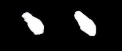
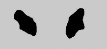
I've changed my mind, however. The object image gets 20.1% larger in area over the course of the clip. This seems to falsify the Venus hypothesis.

To find an empirical measure, I made four screenshots from the NYT version of Gimbal — one at the first frame (in which the object is shot in white-hot), one from the last white-hot frame, one from the first black-hot frame, and the last frame. In Photoshop I used the magic eraser tool with a tolerance of 64 to isolate the image in each screenshot, then cranked up the contrast, then counted the white or black pixels. Findings:

1. The image in the white-hot segment increases in area from 2507 to 2836 pixels.
2. The image in the differently imaged black-hot segment increases in area from 4115 pixels to 4367 pixels.
3. To make the white-hot segment comparable to the black-hot segment, I multiplied the white-hot measurements by a factor of 1.45. After this adjustment, the white-hot segment increases in effective area from 3635 pixels to 4112 pixels.
4. Thus the effective area increase of the image, over the course of the entire video, is from 3635 pixels to 4367 pixels (20.1%).

This suggests that the object gets about 9% closer over the course of the video.
 

Attachments

  • white-hot tolerance 64.jpg
    white-hot tolerance 64.jpg
    9.7 KB · Views: 182
  • black-hot tolerance 64.jpg
    black-hot tolerance 64.jpg
    9.5 KB · Views: 185
Last edited:
For a little while I was pretty intent on the object in Gimbal being Venus -- its angular diameter is in the neighborhood of 50 arc-seconds, and Venus' angular diameter varies between 10 and 66 arc-seconds. You can also find some amateur IR photos of Venus that include significant glare.

I've changed my mind, however. The object image gets 20.1% larger in area over the course of the clip. This seems to falsify the Venus hypothesis.

To find an empirical measure, I made four screenshots from the NYT version of Gimbal -- one at the first frame (in which the object is shot in white-hot), one from the last white-hot frame, one from the first black-hot frame, and the last frame. In Photoshop I used the magic eraser tool with a tolerance of 64 to isolate the object in each screenshot, then cranked up the contrast, then counted the white or black pixels. Findings:

1. The image in the white-hot segment increases in area from 2507 to 2836 pixels.
2. The image in the differently imaged black-hot segment increases in area from 4115 pixels to 4367 pixels.
3. To make the white-hot segment comparable to the black-hot segment, I multiplied the white-hot measurements by a factor of 1.45. After this adjustment, the white-hot segment increases in effective area from 3635 pixels to 4112 pixels.
4. Thus the effective area increase of the image, over the course of the entire video, is from 3635 pixels to 4367 pixels, an increase in area of 20.1%.

This suggests that the object gets about 9% closer over the course of the video.

The horizon issue mentioned above is a problem, too.

I'm thinking the object appears larger, because it's rising above the clouds a bit and getting brighter. More on this latter.

Being below the horizon isn't a problem from 25,000 ft.
 
For a little while I was pretty intent on the object in Gimbal being Venus — its angular diameter is in the neighborhood of 50 arc-seconds, and Venus' angular diameter varies between 10 and 66 arc-seconds. You can also find some amateur IR photos of Venus that include significant glare.

I've changed my mind, however. The object image gets 20.1% larger in area over the course of the clip. This seems to falsify the Venus hypothesis.

To find an empirical measure, I made four screenshots from the NYT version of Gimbal — one at the first frame (in which the object is shot in white-hot), one from the last white-hot frame, one from the first black-hot frame, and the last frame. In Photoshop I used the magic eraser tool with a tolerance of 64 to isolate the image in each screenshot, then cranked up the contrast, then counted the white or black pixels. Findings:

1. The image in the white-hot segment increases in area from 2507 to 2836 pixels.
2. The image in the differently imaged black-hot segment increases in area from 4115 pixels to 4367 pixels.
3. To make the white-hot segment comparable to the black-hot segment, I multiplied the white-hot measurements by a factor of 1.45. After this adjustment, the white-hot segment increases in effective area from 3635 pixels to 4112 pixels.
4. Thus the effective area increase of the image, over the course of the entire video, is from 3635 pixels to 4367 pixels (20.1%).

This suggests that the object gets about 9% closer over the course of the video.
I ask you. Is it possible that the object is showing an oblique side and subsequently the back? could the object be wider than it is long?
 

We seem to have good agreement in the rate of turn, but our lines of bearing look quite different : https://www.geogebra.org/classic/vb5qg3vf

I don't find them parallel at all, and in my model no plausible trajectory for Gimbal is possible beyond roughly 20-25 Nm. How can we be that much off ? Any idea ? Would you mind to share your model ?
Perhaps it's how I assemble the different segments, I joined them along the jet's path, and rotated each segment until it fit the one before. The arc represents the time the jet traveled at each average turn rate.

1625951889622.png
 
Venus is very hard to believe for me as the amount of bullshitting/incompetence/dishonesty (choose the one you like) would be immense coming from military personals. Put that in perspective on this description of the Gimbal event :
Source: https://twitter.com/uncertainvector/status/1396844938869026817?lang=en
Ryan Graves

@uncertainvector

·
May 24

(6/6) For the record, after seeing 100s of aircraft and countless other air and ground based objects through the FLIR, I have never seen anything like GIMBAL. I think it's clear the Aircrew in the video feel the same way.

How often would an aircrew see Venus on the FLIR moments after rising above the clouds, still below the aircraft's artificial horizon? It wouldn't look like anything Ryan has seen before, since it wasn't anything he and others have seen before.

We can find the location of Venus or any other bright celestial object if we know location, time, and date of the Gimbal video. From what I've read on metabunk, all the military will say is the video is authentic.

How crazy would that be that these guys lock on a bird or balloon (GoFast), and then freakout on Venus just a moment later (GoFast/Gimbal being the same flight) :D Or this all just a huge fake coming from inside the military. On your second point, not sure if we'll ever have more data for these events than what we have already.
 
Back
Top