Does the exclusion of stiffness from Nordenson's falling girder calculations demonstrate anything?

What happens to the component of energy from the KE that bends the falling girder? Does the girder spring back or remain bent? ( as JSO asked re the lack of deformed girders in the rubble)
We are (so far) talking about elastic deformation ("springs in series"), so yes, eventually, the girder will spring back. That doesn't change the point that the springiness of the girder dampens the response on the girder below - less energy to bend the girder below means lower force on the girder. The girders springing back later won't load the connection more than the impact does (unless by some freak chance resonance frequencies from who knows where come together).

Could other factors make up the difference by taking into account stiffness as per TSz?
Don't know. Are you sure you aren't fishing for complcating things to salavage your favorite conclusion?
I think we should wait with introducing further factors until we have a handle on the one Tony brought up.

As said many times, analysis is done in a simple representation of reality. TSz introduces one more level of complexity and that could be a good thing unless it begs introducing another equal or near equal component of the real situation.
We'll see if it turns out to be a "good thing", i.e. significant.

Perhaps Nordenson considered stiffness contributions to be equal to a (or combination of) other secondary contributions.
Perhaps, but if he did, he didn't tell us, nor did he give us his reasons. Anyone who wants to assert this should propose what secondary and considered contributions those would be.


Perhaps we really should just write to Nordenson and ask him, as Jeffrey suggested :)
 
We are (so far) talking about elastic deformation ("springs in series"), so yes, eventually, the girder will spring back. That doesn't change the point that the springiness of the girder dampens the response on the girder below - less energy to bend the girder below means lower force on the girder. The girders springing back later won't load the connection more than the impact does (unless by some freak chance resonance frequencies from who knows where come together).


Don't know. Are you sure you aren't fishing for complcating things to salavage your favorite conclusion?
I think we should wait with introducing further factors until we have a handle on the one Tony brought up.


We'll see if it turns out to be a "good thing", i.e. significant.


Perhaps, but if he did, he didn't tell us, nor did he give us his reasons. Anyone who wants to assert this should propose what secondary and considered contributions those would be.


Perhaps we really should just write to Nordenson and ask him, as Jeffrey suggested :)

FYI--I already wrote Nordenson this morning to ask (1) whether, given the suggestions to the contrary by certain conspiracy theorists, he could confirm that it is his opinion that fires could account for the observed collapse of wtc 7, and (2) whether he could provide his opinion on the discussion of the role of stiffness in this thread. If he replies back to me, I'll let everyone here know (unless he specifically requests otherwise, of course).
 
I don't think Guy or Noah would find that CD explains the collapse or would be needed for that building to collapse. My sense is that they would support the fire cause with aspects of the design and construction playing some role.
 
FYI--I already wrote Nordenson this morning to ask (1) whether, given the suggestions to the contrary by certain conspiracy theorists, he could confirm that it is his opinion that fires could account for the observed collapse of wtc 7, and (2) whether he could provide his opinion on the discussion of the role of stiffness in this thread. If he replies back to me, I'll let everyone here know (unless he specifically requests otherwise, of course).
Thanks!
So you gave him a link? Poor Dr Nordenson :oops:
 
I don't think Guy or Noah would find that CD explains the collapse or would be needed for that building to collapse. My sense is that they would support the fire cause with aspects of the design and construction playing some role.

Any communication with Guy Nordenson should only pertain to the legitimate point raised that it appears his analysis left something out that has pertinence. It would be poor form to ask him anything further.
 
Last edited:
Any communication with Guy Nordenson should only pertain to the legitimate point raised that it appears his analysis left something out that has pertinence. It would be poor form to ask him anything further.

I linked him directly to the thread and didn't summarize or characterize your argument. To the extent he cares to weigh in on this topic, he has your opinion unfiltered.
 
I had some brief professional experience with Guy and his partner Noah (not his partner at the time I believe) and I thought he was a really terrific person. I did see some photos of 9/11 years ago taken by Noah and thought to contact him/them about their reaction to the collapses. I did thinking that drilling into this would be a pretty complicated and time consuming thing... and the structural plans were unavailable back then IIRC. An engineer can do his thing without the structural plans and shop drawings etc. The legal case made that possible along with the release of the technical drawings.

And if I understand the thrust of the case by the plaintiffs it was that the collapse was enabled to some extent by the design and construction... etc. The court had to decide if there were defects or if the design and construction were within normal practice and simply unfought fires were what did the deed.

I am guessing here... that the plaintiffs experts decided to accept the NIST column 79 location of the initiation and the supporting fire data NIST used rather than propose another location/scenario/cause absent fire data and discovered what they believe were the design and construction flaws which led to the collapse.
 
Last edited:
Hi all,

I worked out some math in the attached PDF file, because writing down equations with divisions, subscripts, square roots etc is a nuisance in BB code.

The document has two purposes:
a) To prove that using the "springs in series" formula is equivalent to computing the equivalent force from available energy via stiffness, as Nordenson does, but for two girders with two finite stiffness values
b) To show in a table /get a feel for how varying the stiffness of the falling girder affects the resulting equivalent force.

Comment on a):
The idea is that
  1. both girders, as they collide, experience an equal force at the point they touch each other, but in opposite directions: The falling girder experiences a force -F (nearly) up on its far end (very nearly 0 in from the end), and the girder below experience the same force F (nearly) down about 10 inches away from the col79 connection. And
  2. They each build up strain energies SE as they bend, and continue to do so (always with F(down)=-F(up)) until all the Kinetic Energy KE of the falling beam is used up / the falling beam comes to a stop. At that moment, we have KE = SE(girder below) + SE(falling girder)
So there are now two equations to solve:
  • F(girder below) = -F(falling girder)
  • KE = SE(girder below) + SE(falling girder)
My PDF proves that solving this system is equivalent to using the formula
F = SQRT( 2 * KE *K(effective) )​
where K(effective) is the effective stiffness of two springs in series, using the standard formula
1/K(effective) = 1/K(girder below) + 1/K(falling girder)​
 

Attachments

  • Nordenson_B5_Calculations.pdf
    47.3 KB · Views: 601
Hi all,

I worked out some math in the attached PDF file, because writing down equations with divisions, subscripts, square roots etc is a nuisance in BB code.

The document has two purposes:
a) To prove that using the "springs in series" formula is equivalent to computing the equivalent force from available energy via stiffness, as Nordenson does, but for two girders with two finite stiffness values
b) To show in a table /get a feel for how varying the stiffness of the falling girder affects the resulting equivalent force.

Comment on a):
The idea is that
  1. both girders, as they collide, experience an equal force at the point they touch each other, but in opposite directions: The falling girder experiences a force -F (nearly) up on its far end (very nearly 0 in from the end), and the girder below experience the same force F (nearly) down about 10 inches away from the col79 connection. And
  2. They each build up strain energies SE as they bend, and continue to do so (always with F(down)=-F(up)) until all the Kinetic Energy KE of the falling beam is used up / the falling beam comes to a stop. At that moment, we have KE = SE(girder below) + SE(falling girder)
So there are now two equations to solve:
  • F(girder below) = -F(falling girder)
  • KE = SE(girder below) + SE(falling girder)
My PDF proves that solving this system is equivalent to using the formula
F = SQRT( 2 * KE *K(effective) )​
where K(effective) is the effective stiffness of two springs in series, using the standard formula
1/K(effective) = 1/K(girder below) + 1/K(falling girder)​
Oy, using your equation in the post

F = SQRT( 2 * KE *K(effective) )

with KE = 460,000 ft-lbs due to a 46,000 lb load dropping 10 feet and Keff = 3.698 kips/inch for your Case 1

I get a force of 58,328 lbs., not the 160 kips you show in the pdf. Do you have a discrepancy somewhere?

I see that Case 2 (Cantilever K x 16) is the stiffness of a simply supported beam where it has support on both ends. That is not the case here and I believe it will be much closer to your Case 1 (Cantilever).
 
Tony you are mixing feet and inches. 10 feet would be 120 inches, so KE = 46 kip * 120 in = 5520 kip-in.
Or use Keff = 3.698 kips/inch = 44.376 kips/ft. Either way you get 202 kips. However, Nordenson computed an effective drop hight of the floor slab portion of only 83 inches, not 120, for a PE = 3818 kip-inches. From that he subtracted 6 bits of plastic deformation energy loss explained in section B3 and listed in Table B6.1 and arrived at a net KE of only 3473 kip-inches. That's the KE I worked with.
 
As for the appropriate stiffness formula - really, the formula for simply supported beam is cantilever x16? 2^4? I really don't know the first thing about beam theory - I had an intuition that a factor of 2^n would come in, but the factor 16 is merely what it would take to get to a force about equal the shear capacity. That's a bit of a coincidence here.
 
Tony you are mixing feet and inches. 10 feet would be 120 inches, so KE = 46 kip * 120 in = 5520 kip-in.
Or use Keff = 3.698 kips/inch = 44.376 kips/ft. Either way you get 202 kips. However, Nordenson computed an effective drop hight of the floor slab portion of only 83 inches, not 120, for a PE = 3818 kip-inches. From that he subtracted 6 bits of plastic deformation energy loss explained in section B3 and listed in Table B6.1 and arrived at a net KE of only 3473 kip-inches. That's the KE I worked with.
Right, I did have KE in ft-lbs. and stiffness in kips/inch.
 
As for the appropriate stiffness formula - really, the formula for simply supported beam is cantilever x16? 2^4? I really don't know the first thing about beam theory - I had an intuition that a factor of 2^n would come in, but the factor 16 is merely what it would take to get to a force about equal the shear capacity. That's a bit of a coincidence here.

The deflection equation for a simply supported beam with a concentrated load in the center is

Delta = P x L^3 / 48 x E x I

The stiffness is 48 x E x I / L^3

where a cantilever stiffness is 3 x E x I / L^3

The real issue is the actual stiffness of the girder and attached beams and it is more complicated than that of a simple beam. The north and east wall connections are still somewhat intact while allowing rotation, with the column 44 girder connection having its bolts broken and then acting like a simple support which allows hinging. I can do an FEA to determine natural frequency and knowing mass can calculate stiffness of the assembly.
 
Last edited:
The connection at c44 (and east wall and the slab edge) is such that the falling girder and slab section rotate with practocally no resistance. That end is not fixed firmly to c44 like a flagpole sticking out of firm ground. Therefore it isn't a cantilever.
Also, the end impating the girder below is not free.

My intuition tells me that the situation of the falling girder is nearly equivalent to a beam resting on to roller support on its ends and experiencing a force in or near the middle that's equivalent to F/2 (or 2F?). Think of it this way: Lay the girder statically as in Figure B5.1, ends resting on the c44 seat and on the girder below; what force do you have to apply at midpoint to result in F at the impact point? My problem with this, where I am stuck right now, is that this implies a load on the c44 seat that's equal to F; that would be incorrect IMO, free-body physics tells me the force on the far end is not 0, it's... it's... ...the falling beam would pivot about x=L/3 (nearer c44) if hit by F at the c79 end.
If we were to use such an equivalent scenario, with a different force, that would break the "springs in series" math, I'd have to solve the two equations anew and would get a somewhat different effective stiffness.

I understand that natural frequencies play a role and make things more complicated such that one might want to call FEA to the rescue, but prefer to try this analytically first.

Natural frequency (Fn) is related to stiffness, mass, and static deflection in the general equations

Fn = 1/2pi * SQRT(stiffness/mass)

and

Fn = 1/2pi * SQRT(g/static deflection)

Using the above two equations, and knowing the static deflection needed to be at least 83 inches, we can find the natural frequency and the maximum stiffness.

Fn = 1/2pi * SQRT(g/static deflection) = 1/6.28 * SQRT(386/83) = 0.343 Hz

Fn = 1/2pi * SQRT(stiffness/mass)

Stiffness = (Fn * 6.28)^2 * mass = (0.343 *6.28)^2 * 46,000 lbs./g = 6,633 lbs./inch

Using Nordenson's equation on page 245 to find deflection at impact and his PE of 3,473,000 in-lb we have

3,473,000 in-lb = 1/2 stiffness * deflection at impact^2

deflection at impact = SQRT((2 * 3,473,000 in-lb)/stiffness) = SQRT((2 *3,473,000)/6,633) = 32 inches

Now using F = K * D

F = 6,633 lb/inch * 32 inches = 212,256 lbs.

The stiffness value for the girder and beam assembly of 6,633 lbs./inch is higher than the simple cantilever value of 3,707 lbs./inch for the girder. However, the force generated at impact is only about 1/3rd of the 632,000 lb. force needed to shear the seat at column 79 on the lower floor. I think this 212,256 lb. force is a maximum, as the 83 inch static deflection is a minimum and a greater static deflection of the assembly would give it a lower natural frequency and a lower stiffness and less force would be delivered.
 
Last edited:
"...knowing the static deflection needed to be at least 83 inches..."
Why??
The girder and adjoing floor area fell and in the process damaged the connections where they hinged. This is not a cantilever vibrating around the c44 connection!
 
"...knowing the static deflection needed to be at least 83 inches..."
Why??
The girder and adjoing floor area fell and in the process damaged the connections where they hinged. This is not a cantilever vibrating around the c44 connection!
To reach the lower floor you need the assembly, which is still connected to the east and north walls, to deflect at least 83 inches. I am not considering just the column 44 simple support. It is the entire assembly. Admittedly, this is a simplified approach. I will also do an FEA this week to determine static deflection and natural frequency.
 
For those who might think 212,256 lbs. is a low value for the force imparted by the falling girder and beam assembly they need to be reminded that this is amplified from just 46,000 lbs. and amounts to about 5g's of amplification.

It also fits well with the velocity shock equation of

g's = (2 x drop height) / deflection at impact

where the drop height = 83 inches and deflection at impact = 32 inches. In that case, we get

g's = (2 x 83 inches) / 32 inches = 5.1875

which would give a force of

46,000 lbs. x 5.1875 g's = 238,625 lbs.

5.1875 g's is the same as a 166.9 ft/s/s or 2,002.8 in/s/s deceleration rate.

The time for the fall of 83 inches at free fall would be

t = SQRT(2 * drop height /g) = SQRT(166/386) = 0.656 seconds

the velocity at impact would be

v = g * t = 386 in/s/s * 0.656 seconds = 253.2 in/s

duration would be

duration = change in velocity / deceleration = 253.2 / 2002.8 = 0.1264 seconds or about 126 milliseconds.

The numbers seem to fit what one would expect from a low frequency and relatively low stiffness long and large item, since there would be a significant deflection on impact and the deceleration would not be instantaneous.
 
Last edited:
200,000# as a point / concentrated load seems awfully destructive. Doesn't it?
It would not be a point load, as it would have been spread during the deflection of both the falling beam and concrete. It would chip the concrete and pretty much the entire 200,000+ lbs. of force would have been transmitted to the seat due to the hardness of the concrete, but it could not overcome the 632,000 lb. shear capacity of the girder seat at column 79. It seems the notion of the girder falling and causing a cascading collapse of floors below is a myth.
 
Last edited:
To reach the lower floor you need the assembly, which is still connected to the east and north walls, to deflect at least 83 inches. I am not considering just the column 44 simple support. It is the entire assembly. Admittedly, this is a simplified approach. I will also do an FEA this week to determine static deflection and natural frequency.
There is no significant elastic response from the hinges - Nordenson treats the hinges as plastic and has already deducted an appropriate amount of energy dissipation. You are on a completely wrong track here: The girder simply fell 83 inches. This is not a deflection, and it has nothing to do with how far the falling girder will deflect from impacting the girder below.

I suggest you take some paper and pencil and draw a little, and think before you do a FEA.
Maybe start with this:


Circle the pivots, draw arrows for forces, think about what the curve of the beam will look like when bent.
Although there would be some slowing from the deformation at the connections at the east and north walls, I am not considering that. In case you didn't notice, I am considering the assembly to be free falling in rotation about the hinges.

It sounds like you don't like the result. Well, it is what it is and it sounds fairly reasonable. Your own figure shows at least 32 inches of deflection by the falling girder, which is 33 inches deep. The girder and beam assembly is going to bend significantly at impact and that causes the energy to be absorbed over time and reduces the deceleration and thus the force.

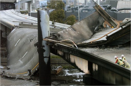
There is also precedent for what my calculations show would most likely have happened and that is the highway overpass collapse that happened in Oakland about 10 years ago. The upper section fell onto the lower section but did not collapse it. See the attached photo.

Dr. Nordenson should correct his report to use the stiffness and deflection of the falling beam and girder assembly and not a point load. I don't expect his results will differ much from what I have done here.
 

Attachments

  • Oakland highway overpass collapse.jpg
    Oakland highway overpass collapse.jpg
    157.3 KB · Views: 483
Last edited:
I made a proclamation? Do proclamations usually contain the words " do"( in an interrogatory sense), and"not sure", in your world?
After reading over this thread I realized I somehow replied to you instead of Jeffrey Orling, for whom I intended the comments saying he shouldn't make proclamations while also acknowledging that he didn't understand the math and found it confusing. They weren't for you.
 
In case you didn't notice, I am considering the assembly to be free falling in rotation about the hinges.
Of course.
After the girder's center of gravity has decended 83 inches. It didn't deflect 83 inches, and it will not deflect 83 inches in the impact starting next.
83 inches play no part in what we are discussing now. Any value for stiffness you derived with an assumption of 83 inches deflection must be a useless nonsense value.

It sounds like you don't like the result.
No, it sounds like I don't like your model. It's wrong.

Well, it is what it is and it sounds fairly reasonable.
No, it sounds plain old wrong.

Your own figure shows at least 32 inches of deflection by the falling girder
My own figure?? Figure for what? Stiffness of the falling girder? I don't have an own figure for that.
YOUR stiffness of 6.633 kip/in shows 32 inches of deflection, but I repeat myself: That figure is wrong because you derived it from a nonsene premise of 83 inches "deflection".

which is 33 inches deep.
So what?

The girder and beam assembly is going to bend significantly at impact and that causes the energy to be absorbed over time and reduces the deceleration and thus the force.
Well yes THAT is true, I have been implying this the whole time, it's where you and I agee. We so far disagree on how much energy is absorbed by the falling girder and how much the equivalent force is thus reduced.

This requires a correct derivation of the applicable stiffness of the the falling girder.
It is not cantilevered at c44, and it doesn't deflect 83 inches at any one time, so your first two shots in the dark missed.

Try to make a drawing of the situatiom circle the pivots, scribble in force vectors, and THINK!
I am doing the same here.

There is also precedent for what my calculations show would most likely have happened and that is the highway overpass collapse that happened in Oakland about 10 years ago. The upper section fell onto the lower section but did not collapse it. See the attached photo.
That's cool, but an overpass is not an office floors. An overpass is designed for much higher loads, and more dynamic loads perhaps.
I have a counter-example - several actually: Ronan Point for example. I won't bore you with details.

Dr. Nordenson should correct his report to use the stiffness and deflection of the falling beam and girder assembly and not a point load. I don't expect his results will differ much from what I have done here.
I agree that Nordenson's report must be corrected, and don't have a strong expectation of where the result will land.
 
Of course.
After the girder's center of gravity has decended 83 inches. It didn't deflect 83 inches, and it will not deflect 83 inches in the impact starting next.
83 inches play no part in what we are discussing now. Any value for stiffness you derived with an assumption of 83 inches deflection must be a useless nonsense value.


No, it sounds like I don't like your model. It's wrong.


No, it sounds plain old wrong.


My own figure?? Figure for what? Stiffness of the falling girder? I don't have an own figure for that.
YOUR stiffness of 6.633 kip/in shows 32 inches of deflection, but I repeat myself: That figure is wrong because you derived it from a nonsene premise of 83 inches "deflection".


So what?


Well yes THAT is true, I have been implying this the whole time, it's where you and I agee. We so far disagree on how much energy is absorbed by the falling girder and how much the equivalent force is thus reduced.

This requires a correct derivation of the applicable stiffness of the the falling girder.
It is not cantilevered at c44, and it doesn't deflect 83 inches at any one time, so your first two shots in the dark missed.

Try to make a drawing of the situatiom circle the pivots, scribble in force vectors, and THINK!
I am doing the same here.


That's cool, but an overpass is not an office floors. An overpass is designed for much higher loads, and more dynamic loads perhaps.
I have a counter-example - several actually: Ronan Point for example. I won't bore you with details.


I agree that Nordenson's report must be corrected, and don't have a strong expectation of where the result will land.
I understand your complaint but there is no other way to do it by hand. Whether you agree or not there is some merit to using the 83 inch deflection. I will do a modal analysis this week using FEA software. That will let us determine stiffness without static deflection.
 
Last edited:
I understand your complaint but there is no other way to do it by hand. Whether you agree or not there is some merit to using the 83 inch deflection. I will do a modal analysis this week using FEA software. That will let us determine stiffness without static deflection.
Substitute FEA in place of thinking?
Sound like a recipe for fail.
 
Substitute FEA in place of thinking?
Sound like a recipe for fail.
No, FEA can be used to set up the end conditions and do actual stiffness calculations based on the modulus and moment of inertia of the structure on a much finer level than can be done by hand. We can only do that by hand with specific equations for specific configurations.

Just so you know the four 3004 W24 x 55 beams are cantilevers and have a stiffness of 1,217 lbs./inch, and their natural frequency and stiffness will drop with the girder as a lumped mass at their ends. Don't be surprised if the FEA doesn't give you much better results than the 6,633 lbs./inch I calculated by hand. I think what I did had some merit although it was a simple approach.
 
I understand your complaint but there is no other way to do it by hand. Whether you agree or not there is some merit to using the 83 inch deflection. I will do a modal analysis this week using FEA software. That will let us determine stiffness without static deflection.
What exactly will be your model? Are you starting from scratch or are you using any data points from Nordenson?
 
No, FEA can be used to set up the end conditions and do actual stiffness calculations based on the modulus and moment of inertia of the structure on a much finer level than can be done by hand. We can only do that by hand with equations.

Just so you know the four 3004 W24 x 55 beams are cantilevers and have a stiffness of 1,217 lbs./inch, which will drop with the girder as a lumped mass at their ends. Don't be surprised if the FEA doesn't give you much better results than the 6,633 lbs./inch I calculated by hand. I think what I did had some merit although it was a simple approach.
If you model the beams and girders as cantilevers after the support at c79 has been removed and the triangular floor assembly has dropped 83 inches, at which time the girder ends collide, then whatever method you use will fail: Equations will fail because you pick the wrong equation. FEA will fail because you model it wrong.
I am not even saying your stiffness value is too low - only that it is wrong.
You are guessing and it is clear that you don't know. The assembly acts like a cantilever in a sense as it hits on one end. Your intuition seem to be that it would have a stiffness like it was falling as a horizontal unit because there is little restraint at the east and north walls. The stiffness is very different when the load is on one end and the other is supported (fixed or simply supported).
 
You are guessing and it is clear that you don't know. The assembly acts like a cantilever in a sense as it hits on one end. Your intuition seem to be that it would have a stiffness like it was falling as a horizontal unit because there is little restraint at the east and north walls. The stiffness is very different when the load is on one end and the other is supported (fixed or simply supported).
You seem to be describing what Nordenson did to determine his PE for the floor impact. He removed the connection at column 79 and used the gravity reaction at that point (in his SAP200 model).
 
Remember that we are looking at the following situation:


The red girder is currently rotating about a pivot at c44. It is NOT cantilevered at c44, it is supported instead by a ... a roller? I am not sure of the terminology.

The left end point doesn't move (it merely rotates).
The right end moves in the direction of the downward F vector I drew. The midpoint moves half as fast in the same direction (for an infimitesimally small distance - direction of course changes, but not by much after the impact has begun, because the girder below doesn't deflect much)

Now consider the red girder as a free body: As it hits the girder below, it experiences a force roughly upward at its right end - the upwards F vector I drew. This imposes angular moment on the beam; as a reaction, there will be a force on the left end by the roller. I believe at this time that the force on the left end is not 0 but F/2.
This would be equivalent to a static girder simply supported on both end with a point force down L/3 away from the right end, and I think its value is 1.5 F. That result in F on the right end and F/2 on the left end.
So the stiffness we are looking for is that of a simply supported beam with asymmetric 2:1 point load.
And we can't use the "springs in series" formula in this model. There is an equivalent stiffness applicable to a load at the right end (F), but I so far keep tying knots in my brain trying to nail down the equation for that.

The maximum deflection of such a beam is ... too complicated a formula to write in BB-code. Refer to
https://en.wikipedia.org/wiki/Euler–Bernoulli_beam_theory#Three-point_bending
and look for wmax in the case of asymmetric load.

I am too tired to do the algebra tonight. Or draw a better diagram than the one above (the mid-point "F/2" is nonsense)
 
You are guessing and it is clear that you don't know. The assembly acts like a cantilever in a sense as it hits on one end. Your intuition seem to be that it would have a stiffness like it was falling as a horizontal unit because there is little restraint at the east and north walls. The stiffness is very different when the load is on one end and the other is supported (fixed or simply supported).
A true cantilever resists rotation at the hinge.
This is not the case here (or rather insignificant).
I realize that treating this a simple horizontal beam isn't right, either. The free body force that bends the falling girder wouldn't be centered. But I think it is closer to the truth than a cantilever.

We will see with the FEA. The four 3004 beams to the right act as cantilevers since their bottom bolts will still be intact and they will bend at that point. Beam G3005 will pivot from the east wall and still have lateral support from the three short support beams going to the north face. They will have their top two bolts broken by the rotating load and they will rotate on the bottom bolt. Beam P3016 to the west of girder A2001 will behave the same way the 3004 beams do. The beam seat on the walls are fixed and the beams will only be resting on them with a preload on their bolts. Girder A2001's bolts are broken, its seat will be fixed and it will just be resting on its seat at column 44.
 
Last edited:
Back
Top