they have kid block sets that are magnetized. would cost like 1,950$ to build a 8 foot core but at least someone could have fun with them once the experiments over
There's also things like this (Rogers Connection, currently unavailable). Pretty much only works for triangular lattice structures though. No stability otherwise.
http://plastruct.com/product-category/structural-shapes/ Trusses start here http://plastruct.com/product-category/structural-shapes/page/4/
The concrete slabs outside the core were poured single pieces. Portions of the slab on opposite sides of the core could not move completely independently of each other. Was there a stack of floor slabs at the bottom after the "collapses" on 9/11? psik
There is no evidence and it's completely unreasonable to expect the floor plates to drop as a single object. The floor plate failures were local due to local overloading... the process however spread rapidly to involve the entire floor area.. and so the entire floors collapsed over a very very short span of time.
The concrete floors broke up under a variety of impacts. Unfortunately this is not something that's plausible to model at this scale. The point is to demonstrate the principle of progressive collapse of a structure with a small the upper part pipping the lower part to pieces. Modeling the destruction of the concrete is really a separate topic, and I'd like to keep the discussion here focussed on the simple model - which again is an illustration some of the principles of the collapse, not a detailed recreation of all the details (which is simply not possible at this scale). However, it might be useful to have a list of what this model does, or does not, model.
Models: Progressive collapse of a free standing structure from the top down Accelerating collapse that cannot be arrested Floors that can support 10x their own weight Failure of columns at splice plates Failure of floors floor slabs at wall column connections "Collapse Front" of chaotic debris Lateral motion of walls Resistance to wind loads Does not model Collapse initiation Core damage Destruction of concrete Overpressure ejections of dust and small debris Upper "block" falling into the lower portion of the building A full 3D floor and four walls. A full set of floors or column section (only modeling 9 or 12, not 110) The right aspect ratio of Height:Width (about 7:1 in the real towers), this would need a 14 foot high version of my current two sided model, or just 8' with the single side, using 2' increments) Buckling or crumpling failure of structural members (except at connectors)
For a detailed overview of the structure of the towers, and the difficulty in modeling them even on a computer, I would recommend reading NIST NCSTAR 1-2 Baseline Structural Performance and Aircraft Impact Damage Analysis of the World Trade Center Towers. The linked version here is "unlocked" so you can copy and paste from it: https://www.metabunk.org/files/NIST NCStar 1-2 101012_unlocked.pdf
I would change: failure of floors at wall connections to: failure of floors plates / slabs at perimeter column connections or similar "walls" unless load bearing is incorrect terminology.
It wasn't just concrete. It was floor pans with the upper knuckles of the trusses embedded in the concrete. Flooring on opposite sides of the core could not move with complete independence. How strong were the connections relative to the weights of the floors? psik
The collapse was not 1 acre sized dropping floor slabs... It was a whole bunch of sections of busted floors dropping ALMOST at the same time... and those chunks involved the entire 1 acre. You can see parts of the floor collapse proceeding way ahead of others. [...]
That said, it might be possible to illustrate some other modes of failure, with an impact (or series of impacts) that is more towards the middle of the floor, there's the potential that the floor will bend in the middle (concrete fracturing), and then subsequent loading will create inward pulling forces. This is demonstrated here: That particular example involved a double wide floor, quite a weak center connection. But it might be better simulated by slicing a few floors in half (and shortening to fit two plates and a magnet), and inserting a four magnet connection in the middle.
But of course the columns were NOT pulled by the collapsing or sagging floors. I believe the IB was most likely buckling from redistributed loads... with the unsymmetrical floor loads which resulted in the bow (buckling) being directed inward. There were many cases of truss seat failures which included rippling off the seats and bending them over as well as ripping the bolts from the trusses.
But in the context of this model and how it relates to the real collapse, there was certainly more lateral forces than could be shown with my very stiff floors, so it's possibly useful to demonstrate it with center-breaking floor - regardless of how much it contributed to the collapse (which is a bit beyond the scope of this thread).
Agreed in the model setting Mick. In the dynamics of the real event the vertical vectors - forces and velocities - were so high that there would be little time for the joist failure and catenary sag pull in to occur. I hinted at it in that original graphic of mine: The "joist starts to bend" shows I recognised the issue but judged that it would get overtaken by the falling mass shearing. Change the caption to "It Fails Here Before the Joist Can Fail in the Middle".
Note: The topic here is this model, what it models, what it does not model, and what the results tell us. This is not for theorizing about what actually happened. There are plenty of other threads for that.
Reading back a few days' worth of posts ... nice progress! A couple of brief ideas and suggestions: 1. Core: Few people understand how the core was framed. That includes people on both sides, for example myself. There are misconception around - Truther, I believe, tend to think the cores were super strong and solid, but as the aerial photo Mick posted a few days ago shows, the cores are mostly air, and the columns, no matter how beefy and strong they are, take up only a small percentage of the area and volume of the core. (Overall, approx. 2% of the towers' cross-section was columns. For the core, that's perhaps 6-8%). It would be great to have a model that demonstrates this flimsiness, but perhaps a separate model is more realistic 2. Perimeter: Before going more realistic on the core, I'd suggest going more realistic on the perimeter: Do a square model with 4 corner columns initially, then 9 and 16 perimeter columns. Give them spandrels. Those need not be beefy at all - sheets of plastic or some such.
The number of connections starts to rise quite quickly as we go into the third dimension. How would you suggesting doing the floor slabs with four corner columns?
At risk of being my normal repetitive and boring self.... ...I suggest that you, we, us take a long serious look at what objective we are pursuing. I have zero problem with any of them but the differences are significant: 1) Pursuing our own pleasure in building models; I can empathise with that one - my workshop is equipped for most "do it myself" tasks short of brain surgery. 2) Exploring the applied engineering science of building collapses in general; Some people need models some don't. I'm in the latter group. 3) Exploring the forensic science of the WTC collapses; take care that the topic doesn't drift off chasing alligators teeth forgetting the objective was "drain the swamp" I've cautioned about drift several times; 4) Building a demonstration to persuade members such as Cube Radio and aka about the undeniable realities of WTC9/11. My opinion of the chance of such conversion being successful should be obvious. You will not see any "Road to Damascus" turn-arounds. Some of you are more generous and more optimistic than I am. BUT if you still want to convert them PLEASE make sure the model is true to the real event. It would be a hollow victory to convert one of our entrenched members to an explanation which is just as false as his own. :curiosity
I agree with Ozzie's last post #100. I think the models can be of use to some who can't visualize. On the other hand I would make it VERY VERY clear what each model attempts to teach / demonstrate. Since forces, time and strength of materials cannot be scales... the models cannot show a scaled down version of the real deal. By change aspects of the model you can demonstrate various "processes" or failure modes... maybe even several in mode demonstration... but not all. The model and the materials... and the connections etc. should be designed to illustrate the chosen failure mode(s) You can demonstrate progressive collapse without arrest... but the collapse was not "pancakes" or solid plates. Why not use 10 segments to make one floor span... how would it break? You can demonstrate some chaos and ejections is the model is "sealed" and includes light elements and openings in the facade... the material can collapse down and perhaps out. Demonstrating "ejections" would be a decent goal. You can demonstrate slender column instability... But can you get the direction of toppling to be away from the tower for the perimeter column panels? Each model does not have to demonstrate ALL features.... that would be a huge hurdle and model real world which to me seems unattainable. I think the models are excellent as teaching tools.
In the "chemtrail" community there's a a very common belief that contrails cannot persist. It's a very simple and very fundamental belief that is flat wrong, and demonstrably so by a simple inspection of any book that mentions contrails in the last 70 years. It's not a belief held by all the top promoters of the conspiracy, but it's held by a majority of the base. It's also something that can be explained as being wrong, and a great stepping stone for a believer to climb out of the rabbit hole. 
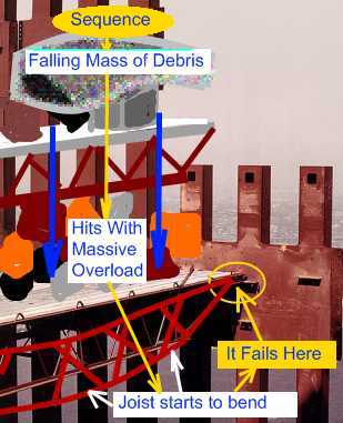
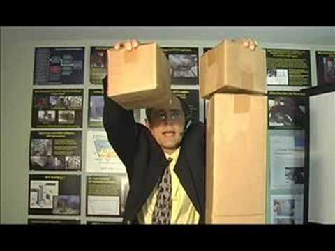
I think the "top of a building cannot crush the bottom" belief is very similar. The "contrails can't persist and spread out to cover the sky" refrain of the chemtrailer has similar echoes in the truther with "near free-fall" and "through the path of most resistance". These very simple, yet foundational, beliefs are held by many quite reasonable people. People who think models like this actually mean something: I think that a model that demonstrate the very simple principle that "the top of a building CAN crush the bottom" would be very valuable here. It's a a necessary stepping stone to understand why the AE911 claims of "evidence" are largely based on misconceptions. 
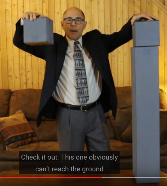
Of course I do not want to replace one misconception with another. What I want to do is very simply to demonstrate that the "cardboard boxes" model is wrong, and that the a "complex progressive collapse" (for want of a better descriptive name) model is quite possible,
Mick, You are correct. The Gage model is a not in anyway a representation of the building's structure. The top was not a block.. and if you could drop the real top from 1100' it would fall at close to FF less the air resistance. We've tried for 15 years to explain that what was collapsing and being destroyed was the FLOOR system along with the contents on the floors... Your model amply demonstrates THIS aspect or the collapse AND it shows how stacked columns are unstable without the connecting bracing of the floors and they break apart at the column to column connections. Your model demonstrates (not reproduces) these two KEY aspects of the collapse perfectly... collapse times / speeds/ sequence... It does not show the fracturing and dustification of the slabs nor the ejecting of material through the facade glass. Gage's model is [...] and demonstrates absolutely nothing about the collapses on 9/11.
I am not a talented or experienced craftsperson, so I'll shy away from suggesting technical solutions. However: My main suggestion is to go 3D on the perimeter instead of the core. Once reason is that we know from plenty of photo and video evidence that many (most) the wall panels (3 storeys x 3 columns) survived complete. This allows your model to tie 2 or 3 columns together with rigid connections, reducing the number of connections you need to scale just right with your magnets. What I want to see is whether and how wall sheets do the banana peel. I am thinking of doubling the corners (the actual towers had those 45° corners, i.e. there was a spandrel connection between the left and right edges of adjacent faces) - 8 columns, 2 on each corner. Connect the two columns on one corner rather loosely (weak magnets?), and the two columns of a face very rigidly (screwed-on thin wood or plastic sheets). Roughly like this: 31-----2 31-----24 |1-----2| |1-----2| 51-----26 37-----8 1-2, 3-5, 4-6, 7-8 would be rigid 1-3, 2-4, 5-7, 6-8 would be loose Connect floors to all 8 columns. ETA: In this simple 3D, floors would obviously be square slabs. One to two step up the complexity ladder would be a single thick core column, and 4 slabs per floor - perhaps long and short bays. Not sure how to connect the floors (not sure how strong they were in reality; if homogeneous, or if there are sort of predetermined breaking lines)
Another note: It's important to keep the discussion polite, so we don't alienate people. Most people have very little experience with physics, so describing a particular explanation as "stupid" is kind of like calling the average reader stupid. Calling names sets up barriers to communication. If a particular theory or model has problems, then let's demonstrate those problems in a way that is accessible to the average reader/viewer. I recognize not everyone agrees with this approach, however Metabunk is a polite forum, and politeness will be enforced.
I would have thought that the falling away of both sides of the 2.5D model demonstrates this peeling to a degree? Were you more interested in broader "sheets" of a single wall, or the falling of the walls outwards in four directions (rather than 1 or 2 with the current model).
Oy, There were 3 different floor areas... but the facade was pretty similar... I think the facade columns on the short span side were likely thinner and weaker than those on the long span side. You had floors which were approximately rounded off to the nearest 5'" 2 - 135 'x 60' long span 2 - 90' x 35' short span 4 - 35' x 60' corners NB that the corners were supported by two adjacent sides and a transfer truss/girder to the belt truss the short and long were 2 way slabs supported on the belt gider and the facade. I'll make a drawing of the next level of complexity... but Mick should get financial help from members.
Question: The wall sections are 3 floors high with splices mid-floor. Are the core columns the same? i.e. are the core column sections the same height as the wall sections (like I have in my model)?
All column splices core and facade were about 3' above the slabs... done to make fabrication easier All columns EXCEPT the mech floors were 36' tall... the mech floors are 32' tall
I am attaching an drawing of a more complex model.. very quickie... no dimensions... concept for a floor The floor slab pieces can have paper glued on their joining edges to have them act composite (somewhat) Perhaps this need to be only 3 columns high??? 9 floors. You could try to collapse it with partial floor drops in different sections... Long span Short span Corner Core The collapse of one section should propagate (hopefully) laterally as well as vertically in 4D
More complex? That's about 35 times more complex! While there's plenty of room yet for various experiments and enhancements to the physical model, I'm wondering if a (simple) computer model might be the way to go in scaling up complexity (and physical scale). Essentially I'd be creating a computer model of the current physical model, so the physical model would serve as "ground truth" of the basis of the computer model. The computer model should be able to replicate the physical model with such a high degree of fidelity that doing things like adding four more floors, or extending it to a multi column layout like yours. It would still be something that is demonstrating principles though, not a precise representation of the towers themselves.
I know this is was more involved... but people tend to trust physical models more than computer models.
Another update. Got some MDF (Medium Density Fiberboard) in 1/4" sheets and cut these to size for the "outer walls". Also picked up a few tie plates to use as splice plates. MDF is better looking and has a realistic degree of flexibility. Video also demonstrates a 6 floor progressive collapse with the new magnet system.
You don't need two, but with just one it's slightly weaker in one direction (and half the strength overall).
Unfortunately Amazon messed up my magnet order, so it's going to take a few more days before the 8' model will be complete. But in better news I found the same spec magnets even cheaper on ebay. $20 for 100 http://www.ebay.com/itm/lot-100-50-...-Earth-N35-Small-Fridge-Magnets-/191570155765
Don't have much time to post. Read several posts and have a question. Were the floors tested for max static load capability? That would give you a scale for impact force. Drop a mass that will only equal that static load quantity when dropped. Dynamic load equals max static load. Use a mass that can come apart on impact(washers taped together.for eg.) Does collapse progress past initial impact?
Yes, although my standard was the NIST figures of 6-12 times their own weight for a floor assembly. Progressive collapse is pretty much assured with a mass equal to three times the weight of a floor dropped from the height of one floor. Generally the collapses accelerate all the way down.