Why Do Sagging Floors or Trusses Pull Walls Inwards

Mick West

Administrator
Staff member

Source: https://www.youtube.com/watch?v=6obTq2UrCiU


A large part of the reason that 9/11 conspiracy theories persist is simply that people not understanding the physics of the collapse. I was talking to a conspiracy theorist a while back, trying to explain why the towers collapsed. I said that the floor trusses were heated until they sagged, then they pulled away from the walls. Here's a visualization of this with the floor slabs removed so you can see the trusses.


Source: https://youtu.be/XpfDkL-vFdk?t=48s


He asked why would they pull away from the walls. They were not any heavier. They were still attached to the walls. It was still the same mass being supported by the ends of the truss, so why would it pull? It made no sense to him.

I realized I'd not really given it much thought myself. I had to consider for a moment before realizing it was the loss of stiffness that essentially turned the floors from rigid rods to ropes. Catenary forces come into play. I tried to explain this.

The video above is my attempt to demonstrate it. I do it two ways. Firstly with two identical chains. One has the links welded together so it's a stiff rod. The other is just loose. The loose chain pulls in the columns. The stiff chain does not.
Metabunk 2018-03-06 14-08-35.jpg

Secondly I make a "floor" out of a steel box tube with some weights. I heat it until it sags in the middle. Then it pulls in the end "columns".
Metabunk 2018-03-06 14-10-46.jpg

I think another part of the problem with a lot of 9/11 explanations is that they lack a practical demonstration, so people don't really get a real sense of what the explanations mean. Hopefully this will help a little.

UPDATE: Here's another demonstration I did this morning. In this one the chain is encased in ice, and gradually transitions from rigid to sagging.

Source: https://www.youtube.com/watch?v=zTygQK3vriI
 
Last edited:
Myles Powers had a pretty good explanation on one of his 9/11 debunking videos where he discussed the unique construction of the twin towers and how the buckling of the floor joists pulled the walls inward. I'll see if I can find it.
 
I was asked what the temperature was that the "beam" failed at. I'm estimating about 650°C (1200°F) on the upper end. I repeated heating the bar with a cheap thermocouple attached. It seems to top about over 700°C when heating the thermocouple directly. It was in the 600°C to 650°C range heating the bar itself. It cools down very rapidly.
Metabunk 2018-03-06 15-28-12.jpg

The bar did glow orange in this temperature test. But I don't recall it glowing in the bend test.
 
Last edited:
No thermal expansion was visible to the naked eye, HOWEVER there's some interesting effects. When I first heat the beam in the middle with the smaller blue propane torch, the two block rise up. I'm heating the bar on top, the thermal expansion is greater on top, so it makes the bar want to curve upwards. So the blocks rise very slightly and rotate outwards
Metabunk-2018-03-06-15-50-15.gif

The beam then does seem to expand a bit (maybe 1mm) up until the sag starts to set in. Watch the top of the "column" on the right here.
Metabunk-2018-03-06-15-55-21-2.gif

(Note the background shifts slightly too. I think this is due to the image stabilization in my Nikon P900)

Did you consider that the softening of the material in the beam begins to cause the beam to lengthen (pushing the wall outwards at first as you said) but then as the beam begins to be pulled downward (it would not go up under load), the chord is now shorter than the beam's original length and the weight of the beam begins to be off-centered (no longer straight down so the forces are pushing the walls outward as well) which adds to the downward pull and the walls are then pulled in as the softening of the beam causes the chord to become still shorter as the beam fails?

The pinning on to the walls also failed as well - I'm not familiar with how these are actually constructed, but your analysis seems to be right on. Once the pinning on either end is broken, the other end hasn't a chance to hold it and the softened beam pulls away, the weight of the bent beam with broken pinning falls as a chunk taking floor after floor as it falls. Isn't that the way the final report explained it, too? Even if the beam did bend upwards at first, that would stress the pinning and when the beam began to fail, it would become shorter as it sagged and the floor would fall as soon as it got off the pinning surface. It would be a fairly catastrophic sag - the ends would be not inches but feet inside the walls. The falling floors would pull the walls inward and the weight above would make the whole thing come down in the center. Just like it did.

What is more surprising to me is that it doesn't appear that they use more off-sets to stiffen things between floors - it looks like the buildings are built on the outside structure with nothing inside after the first floor or two. I have some experience with single family dwellings and there they use offset walls to provide the support and keep the upper floors from flexing - I'm sure it is a completely different ballgame.
 
Watch the top of the "column" on the right here
That's likely aided in parts by the slight rotation of the 'cross beam' between the nails. Its lower edge is pushing against the outer nails
 
Last edited:
A different perspective on this very issue which may interest or amuse. A few years back in a discussion with Tony Szamboti I threw in a casual comment "But catenary sag is a very effective force multiplier." The discussion was with engineers/physicists and I took the comment as being self evident...several pages of opposing discussion followed and in frustration I made an observation that the concept was simple enough that a 10 year old could understand it.

Then my grandson - 6 yo at the time - came visiting and I set up an experiment. It was somewhat fun parody BUT the physics is spot on accurate - a couple of leading questions when I "interviewed" the 6 yo star performer to allow for his age and vocabulary. Here is the post:
http://www.internationalskeptics.com/forums/showthread.php?postid=9418049#post9418049
 
Did you consider that the softening of the material in the beam begins to cause the beam to lengthen (pushing the wall outwards at first as you said) but then as the beam begins to be pulled downward (it would not go up under load), the chord is now shorter than the beam's original length and the weight of the beam begins to be off-centered (no longer straight down so the forces are pushing the walls outward as well) which adds to the downward pull and the walls are then pulled in as the softening of the beam causes the chord to become still shorter as the beam fails?
I think you might need a diagram there :)
 
A different perspective on this very issue which may interest or amuse. A few years back in a discussion with Tony Szamboti I threw in a casual comment "But catenary sag is a very effective force multiplier." The discussion was with engineers/physicists and I took the comment as being self evident...several pages of opposing discussion followed and in frustration I made an observation that the concept was simple enough that a 10 year old could understand it.

I think it's one of those things that's self-evident from a practical perspective - i.e. if you've ever tried to hang a hammock between two sturdy seeming sticks you pounded into the ground. Or if you've tried to make a taut 30 foot length of rope not sag in the middle. Or if you've done the math.

But if you get into the physics for the first time it's rather confusing. Where are the forces going? Why is the force at the walls so massive.

It can be helpful to think of the floor first as a rigid slab, and then as two rigid slabs joined by a hinge in the middle, then with progressively more hinges. Then imagine putting weight on each of these different floors (or imagine the floor sections themselves being made of heavy steel bars, which essentially they are).
Metabunk 2018-03-07 07-10-39.jpg
In case A, the undamaged floor you can see that, like my rigid chain, the weight is simply supported at the ends.
Metabunk 2018-03-07 07-13-10.jpg

But in case B, with a single hinge in the middle you get essentially massive torque (a turning moment, a bending force) at the supported ends. What happens then depend on how the ends are connected (and how well they are connected).

If they are simply resting on the seats, them they will simply pivot up and off. If they can pivot, then they will rotate about that point, and pull inwards as the center of the floor moves down. If they are firmly fixed to the walls (moment resisting) then they will twist the wall, pulling in the wall above the connection, and pushing out the wall below it (although they will also be pulling in so the major motion will be inwards, depending on the length of the floor span).

The reality of the situation is a more complicated system, with variable stiffness in the floor due to uneven heating. It's a struggle to explain the forces involved even to people with some basic physics knowledge, so I think the practical demonstration route is the way to go.
 
Last edited by a moderator:
I have to modify my temperature claims from around 650°C to (possibly) around 750°. Keep in mind I'm just measuring this with a thermocouple that came free with the multimeter, but it seems to respond well, and is accurate at low temperatures.

The question of how hot my torch can make things is an interesting one as it relates to heat (an amount of energy) vs. temperature (a measure of how energetic some piece of matter is).

My torch is a Bernzomatic TS8000 MAP-Pro (Propene/Propylene). The specs say the flame temperate is 3,730°F, 2054°C. Does that mean it can melt steel (melting point 2750°F/1510°C)? No

If I heat my thermocouple alone, it gets to 1150°C, glowing yellow hot even in sunlight. It gets to this temperature in 12 seconds.
Metabunk 2018-03-07 14-31-56.jpg

If I heat the thermocouple clamped on top of a thin steel square tube it gets to 1050°C in 60 seconds, then no higher.
Metabunk 2018-03-07 14-34-07.jpg

If I clamp the thermocouple underneath a 1/4" steel bar:
Metabunk 2018-03-07 14-35-36.jpg
(That's 25.9°C there)

I then heat it from the top, it gets to 764°. It took over five minutes for this to happen. At that temperature even minor movements of the torch would cause the temperature to drop.
Metabunk 2018-03-07 14-37-45.jpg
The reason being is that the flame can only supply heat at a certain rate. The metal the flame contacts is swimming in 2000°C hot gas, but that simply creates a heat flow from the gas to the metal. Simultaneously there's a heat flow along the bar, and another heat flow out of the bar into the much cooler surrounding air, and yet another heat flow from the radiating heat - especially when it gets above red hot.

The hotter you heat it (heat in), the faster the heat flows (heat out). At some point they match, and the steel will not get any hotter.

A thermocouple by itself has restrictions on how much heat can flow away, because it's tiny and not touching anything. So it can get a lot hotter. Still not as hot as the 2000°C flame though. At around 1150°C it's yellow hot, and is simply radiating out temperature faster than it can convect it in from the flame. It's also convecting along its length, and radiating from there too - but mostly from the tip. There's also convection cooling from the surrounding air.

With the thermocouple attached to something, then even if it's heated directly there's now an additional escape route for the heat, through the steel. So the maximum temperature is lower, 1050°C

And when it's on the other side of the steel, the heat has to go through that steel to get to it. The thermocouple is not a bit downstream of the actual heat source, but more accurate reflects what the temperature of the steel is (as opposed to what the temperature of a thermocouple in flame is). So now the hottest I got it was 750°C.

These issues of heat flow and thermal equilibrium are important to understanding some aspects of the WTC collapses.
 
Last edited:
These issues of heat flow and thermal equilibrium are important to understanding some aspects of the WTC collapses.

To expand on that slightly, a large fire burns hotter than a small fire. Not just because the flames are hotter (they are), but because the heat flow is limited by the surface area of the fire, whereas the heat production is limited by the volume of the fire. It's also limited by the oxygen supply, but that can be improved with air flow.

Flames are hotter? Yes they are - because the temperature of the area is hotter, the gases that burn start out hotter. The chemical reaction of combustion adds the same amount of heat, so the end result is hotter flames.

Both of these things play a significant role in kerosene pool fires. If a pool of kerosene is large then it will be heating a lot more of the metal above it, so there nowhere for the heat in the middle to flow out, as it's being heated all along. The general area heat also heats up the kerosene before it ignites, resulting in a hotter flame temperature, and more heat. This is all modulated in probably complicated ways by the availability of oxygen.
 
I think it's one of those things that's self-evidence from a practical perspective - i.e. if you've ever tried to hang a hammock between two sturdy seeming sticks you pounded into the ground. Or if you've tried to make a taut 30 foot length of rope not sag in the middle. Or if you've done the math.
That is where I presumed too much practical common sense understanding in my discussions. Recall that I had two truther engineers - "enik" and Tony Szamboti - and a few "sideline lurker" debunkers who were (still are) FEA fluent practising engineers. enik outright rejected the assertion "...catenary sag is a very effective force multiplier." Tony Sz took it in his stride. And all of them - opponents and lurkers - come from a background where they rely on FEA as foolproof and I had falsified several examples where they lost the plot. BUT the specific "catenary sag" issue is quite straightforward if you dont overcomplicate it.

But if you get into the physics for the first time it's rather confusing. Where are the forces going? Why is the force at the walls so massive.

It can be helpful to think of the floor first as a rigid slab, and then as two rigid slabs joined by a hinge in the middle, then with progressively more hinges......
Maybe. I took a simpler approach and went directly to the central point.
A rigid beam supported at the ends puts 1/2 the vertical load onto each support and has no horizontal inwards force exerted on the columns.

The "half the vertical on each column" does not change if the rigid beam becomes flexible. BUT it does start to pull inwards as we increase the flexibility. So take the extreme of a fully flexible rope and the physics is still simple - the amount of sag determines the inwards pull. Straight forward application of vectors.

- MickWestVectors.png
The "V-vector" is half the applied load - and the "H-vector" and "Tension" in the rope determined purely by the geometry. The more sag in the rope the LESS the inwards pull. Au contraire - reverse that - the less sag - the tighter we pull in the hammock - the more the inwards pull. In the example of the graphic the Horizontal pull in is visually estimated at a bit over 2 times the vertical - itself half the applied load.

And that is for fully flexible i.e. a rope. If the beam is only partly flexible then there is a mix. BUT it is the catenary sag component which causes the inwards pull. Which was all I needed for that other discussion. And the catenary sag component can be isolated from all the considerations of where bending moment resistance comes into play for a less than fully flexible rope>>beam. IF you try to track what happens in the beam....but can be ignored if you can take the beam as a "black box" where the only interest is the external forces on the end points.
 
Last edited:
Catenary loads are only possible when the structural member can no longer take moments and will only transmit tensile loads like a cable.

The reason the NIST model did not produce catenary forces from sagging floor trusses on the WTC Tower perimeter columns is that the trusses could still take moments and withstand compression to a degree. They behaved like Mick's rigid chain just applying force from their vertical load onto their seats.

It seems whoever modeled WTC 7 for NIST understood this and took the moment capacity away from the beams and girders by cutting notches in them. See Figure 12-35 in the NIST WTC 7 report.
 
Perhaps the end connections of the trusses to the spandrel beams on the exterior and the belt girders around the core were not strong enough to pull the columns together because the those connections failed?

The connections were often the weak link in the floor destruction mechanism.
 
Perhaps the end connections of the trusses to the spandrel beams on the exterior and the belt girders around the core were not strong enough to pull the columns together because the those connections failed?

The connections were often the weak link in the floor destruction mechanism.
NIST found, a little against expectations, that this is exactly what did NOT happen in the twins: The floor-to-column connections did NOT fail in tension, which would have caused some first floor to drop, pancake-like, onto the floor below. This is explicitly the FEMA hypothesis which NIST refuted.
 
Mick,

this may expand the purpose of this thread a little farther than you intend:
We need to be clear that, when many inches[1] of inward bowing were observed at the twins' fire floors prior to collapse initiation, this amount of inward bowing was NOT the result merely of sagging trusses pulling inward. Rather, the sagging trusses only provided an initial tug[2], enough inward bowing for the perimeter columns' capacity to drop below extant load. The load then would push the wall further down and further inwards, until enough load had been redistrubuted to other columns with yet sufficient capacity. Most of the visible inward bowing certainly was caused by the vertical load, not by the lateral pull.


[1] I do not recall specific numbers, but certainly more than a foot, or the depth of a perimeter column
[2] Again, I have no numbers, but suggest on the order of a single inch
 
Catenary loads are only possible when the structural member can no longer take moments and will only transmit tensile loads like a cable.

The reason the NIST model did not produce catenary forces from sagging floor trusses on the WTC Tower perimeter columns is that the trusses could still take moments and withstand compression to a degree. They behaved like Mick's rigid chain just applying force from their vertical load onto their seats.

It seems whoever modeled WTC 7 for NIST understood this and took the moment capacity away from the beams and girders by cutting notches in them. See Figure 12-35 in the NIST WTC 7 report.

Metabunk 2018-03-08 07-40-39.jpg

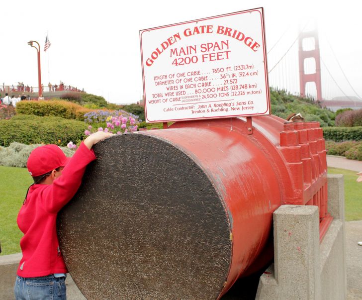
Even a cable has some resistance to moments (bending). Try bending these cables.
Metabunk 2018-03-08 07-47-29.jpg
if you cut the cables on the outside ends of the bridge, then would the towers not fall inwards, despite the presence of some moment resistance in the middle cables?

Catenary loads are possible whenever a stiff structural member suffers a reduction in it's ability to resist moments. If it's actively sagging then it's no longer fully resisting the moment forces, and hence must be acting less like a rigid structure, and more like a chain.

The removed of the sections of beams in the global LS-DYNA model, above, does not remove the moment resistance from the beams, it just greatly reduces it in line with the weakening of the steel from the increased temperatures. This is a simplification for economy in the the model.
 
Mick,

this may expand the purpose of this thread a little farther than you intend:
We need to be clear that, when many inches[1] of inward bowing were observed at the twins' fire floors prior to collapse initiation, this amount of inward bowing was NOT the result merely of sagging trusses pulling inward. Rather, the sagging trusses only provided an initial tug[2], enough inward bowing for the perimeter columns' capacity to drop below extant load. The load then would push the wall further down and further inwards, until enough load had been redistrubuted to other columns with yet sufficient capacity. Most of the visible inward bowing certainly was caused by the vertical load, not by the lateral pull.

[1] I do not recall specific numbers, but certainly more than a foot, or the depth of a perimeter column
[2] Again, I have no numbers, but suggest on the order of a single inch

At the very least the pulling in helped initiate the column deformation, contributed to it's loss of vertical strength, and determined the direction of the bowing.

I might try an experiment with loaded columns AND a loaded floor. It's increasingly difficult to heat larger structures though. I might need a bonfire.
 
NIST found, a little against expectations, that this is exactly what did NOT happen in the twins: The floor-to-column connections did NOT fail in tension, which would have caused some first floor to drop, pancake-like, onto the floor below. This is explicitly the FEMA hypothesis which NIST refuted.

There were no floor to column connections per se. The facade side was connected to the spandrels... horizontal members of the 3 column 3 story high assembly.. ON the core side there was a continuous belt girder surrounding the core perimeter columns. The double floor trusses did not "align" with the columns so the cantilevered girder was a transfer of floor loads to the core perimeter columns.

When the OSS flooring collapsed the weak link was the floor truss to spandrel and to belt girder connections. It's possible that the cantilever belt girders were ripped off by the floor collapse... they certainly were at the top because few horizontal beams survived the floor collapse.
 
Catenary loads are only possible when the structural member can no longer take moments and will only transmit tensile loads like a cable.
Perhaps your objection here is a bit of a tautology, using "catenary loads" as the idealized loads from an idealized infinitely flexible rope dangling from two points? Perhaps we should adopt the more general term "pull-in forces", as used by NIST?

NCSTAR 1-6C

Sagging of the Floor System: Floor sagging caused by loss of stiffness, plastic bending, or
buckling of web diagonal members resulted in tension in the floor subsystem, tension in the
connections to the exterior walls, and lateral forces (pull-in forces) on columns.
Content from External Source
Discussing approximations made when modeling

Pull-in forces were expected to develop whenever the floor sagged. Although the floor sagging was
captured by the full floor models, the pull-in force was not captured in most of the full floor model
analyses. To accurately calculate pull-in forces between the floor and the exterior columns in the full
floor model, much more detailed modeling was required. Such modeling included accurate boundary
conditions on columns, creep in steel, friction at the truss seats, and accurate evaluation of failure of strap
anchors and stud, and concrete cracking and spalling.
Content from External Source

The global model cannot be constructed with the same level of detail in all floors subjected to thermal
loading as the full floor model developed here. To enhance computational efficiency, the pull-in forces
and disconnections of floors from the exterior walls may be implemented in the global models as “fire induced
damage”
at appropriate times. Since the full floor models could not be used to calculate
accurately the pull-in forces at floor/wall connections, the fire-induced damage obtained from the full
floor model analyses needs to be modified by the results of “actual observations” obtained from the
examination of photographs and videos performed by NIST (NIST NCSTAR 1-5A).
Content from External Source
What actually happened:

Floor sagging caused pull-in forces. For instance, Column 101 to Column 111 on the west face and
Column 347 to Column 359 on the east face were pulled in by the floor at 60 min on Floor 80 as shown in
Fig. 5–110 because of the floor sagging occurring in the southeast area. Since core columns were not
restrained in the horizontal directions, when the floor pulled in one face of exterior wall, the opposite face
of the exterior wall was also pulled in. Columns at the southeast corner were pulled in by the floor at
Floor 79 and Floor 81. Many columns of the west face of Floor 82 were pulled in.
Content from External Source
Metabunk 2018-03-08 08-26-44.jpg

Quantification

When floors sag, they begin to pull in the columns. The results of truss component analyses indicated
approximately 14 kip of pull-in force per truss. Strap anchors distributed this pull to the columns that did
not support trusses. A 15 kip pull-in force was applied to each column of laterally-unsupported floors to
model the effect of the sagging floor.
Content from External Source
(14 kip = 14 kilo-pounds = 14,000 pounds force)

NCSTAR 1-6D describes how the trusses transitioned from stiff to less stiff, and how that resulted in catenary forces:

Floor sagging sufficient to cause the observed inward bowing of the exterior wall was caused by
the elevated steel temperatures resulting from loss of thermal insulation. The elevated
temperature caused buckling of the truss web diagonals, as shown in Fig. 5–1 (NIST NCSTAR 1-
6C), which caused the floor sag to increase significantly and to approach a catenary shape. The
catenary action in this study refers to the combined action that results when
(Fig. 5–2). Note that in Fig. 5–2, M refers to the residual moment capacity in the floor
with highly deformed truss. Sagging of the floor resulted in pull-in forces at floor/exterior wall
connections, and led to inward bowing of the exterior wall
Content from External Source


Metabunk 2018-03-08 08-39-39.jpg

Note they explicitly refer to the "residual moment capacity" of the floor. It has not turned into a floppy rope, but it is unable to fully resist the moment (bending) forces, which is why it is sagging.
 
That NIST explanation sounds like garbledy gook to me.

The core columns WERE laterally restrained by the bracing. Look at the plan of the core NIST.

The pull in of the facade was because the CORE side of the floor where you see pull in had no core side support... the floor at that point was essentially cantilevered and the connection pulled at the facade until the bolts sheared and the connection failed. Shear strength of a 5/8"Ø bolt is 1,500#. If the claimed pull in force was 15,000#... each connection would have had to have more than 7 bolts. I don't think the top chords of the double truss had 10 bolts... each one had 2. if the truss had buckled / sagged as they claim the 2-1"Ø did nothing.

http://www.rdfasteners.com/pdf/boltstrength.pdf

No?
 

Attachments

  • core framng.JPG
    core framng.JPG
    522.5 KB · Views: 564
That NIST explanation sounds like garbledy gook to me.

The core columns WERE laterally restrained by the bracing. Look at the plan of the core NIST.

The pull in of the facade was because the CORE side of the floor where you see pull in had no core side support... the floor at that point was essentially cantilevered and the connection pulled at the facade until the bolts sheared and the connection failed. Shear strength of a 5/8"Ø bolt is 1,500#. If the claimed pull in force was 15,000#... each connection would have had to have more than 7 bolts. I don't think the top chords of the double truss had 10 bolts... each one had 2. if the truss had buckled / sagged as they claim the 2-1"Ø did nothing.

http://www.rdfasteners.com/pdf/boltstrength.pdf

No?

No, see NCSTAR 1-6D section 2.5.2: http://ws680.nist.gov/publication/get_pdf.cfm?pub_id=101366

When the floor sagged while it was still connected to the exterior wall, the floor developed tensile forces
that tended to pull the exterior wall inward. There were four types of structural elements that connected
the floor system to the exterior wall system: 1) diagonal strap anchors that extended from the top chords
of trusses to the spandrel (they are referred to as strap anchors in this report), 2) headed studs on the
spandrels that extended into the floor slab edges, 3) gusset plates that were horizontal field-welded plates
that joined the top chords of the trusses to the spandrels, and 4) seat bolts that fastened bearing angles to
the seats that were attached to the spandrels.
Content from External Source
You seem to only be considering the seat bolts, and those only in perfect perpendicular shear.
Metabunk 2018-03-08 09-25-37.jpg
The welded gusset plate can be seen in the diagram above. I suspect also that some of the force would apply to the bolt as axial tension as the bearing angles pivot on the seat angle.

Here's the strap anchors and spandrel studs in plan view. The strap anchors are studded into the slab, but also appear to be connected the the columns.
Metabunk 2018-03-08 09-31-44.jpg

As you cans see there is essentially a truss-to-column connection. The seat is on the spandrel, but it's directly behind a column., The adjacent columns are attached via the strap anchors:
When floors sag, they begin to pull in the columns. The results of truss component analyses indicated approximately 14 kip of pull-in force per truss. Strap anchors distributed this pull to the columns that do not support trusses. A 15 kip pull-in force was applied to each column of laterally-unsupported floors was applied to model the effect of the sagging floor
Content from External Source

The complexity of these connections (especially with the involvement of the concrete slab) made them very hard to model in the global simulation. NIST seems to have used estimated pulls based on observed deformation rather than calculated pulls.
 
The complexity of these connections (especially with the involvement of the concrete slab) made them very hard to model in the global simulation. NIST seems to have used estimated pulls based on observed deformation rather than calculated pulls.


Perhaps difficult to model because of weld performance... but not difficult to test full scale.... which they didn't bother to do. Connections will fail at the weakest point... and YES that may be hard to model...

Why didn't NIST assemble a truss connection to a spandrel and apply tensile stress im destructive testing?

They built trusses and subjected them to fire didn't they?

https://en.wikipedia.org/wiki/Destructive_testing
 

Attachments

  • Panel types.pdf
    61 KB · Views: 704
Perhaps it's a good thing to include a proper explanation what a truss system is, why it's designed the way it is, and how the truss system's stress resistance decreases as the original shape of the system is deformed.

That would likely help some to understand the chain analogy even better.
 
Metabunk 2018-03-08 07-40-39.jpg

Even a cable has some resistance to moments (bending). Try bending these cables.
Metabunk 2018-03-08 07-47-29.jpg
if you cut the cables on the outside ends of the bridge, then would the towers not fall inwards, despite the presence of some moment resistance in the middle cables?

Catenary loads are possible whenever a stiff structural member suffers a reduction in it's ability to resist moments. If it's actively sagging then it's no longer fully resisting the moment forces, and hence must be acting less like a rigid structure, and more like a chain.

The removed of the sections of beams in the global LS-DYNA model, above, does not remove the moment resistance from the beams, it just greatly reduces it in line with the weakening of the steel from the increased temperatures. This is a simplification for economy in the the model.
Vertical loads on horizontal structural elements create bending loads which require tension resistance on the bottom and compression resistance on top. A cable has virtually no ability to generate internal reactions against compression besides friction between strands and wires. The large bridge cable you show would have a very limited amount of moment resistance and would only seem to be able to take moments when carrying a vertical load which was orders of magnitude lower than what it was intended for in tension. That does not make it a moment carrying member. If you cut the cables of a suspension bridge on the outside the reaction to their catenary force would be removed and the load that caused the catenary force would no longer be supported and would fall. That would be the deck, not the towers. The cables do not support the towers of a suspension bridge. The towers of a suspension bridge are self supporting, and are actually supporting the cables vertically and are loaded in compression from the cables on top of them on a saddle. The towers would be relieved of that load at that point and have only their own weight to support, which is far less than they need to be capable of handling without buckling. See https://science.howstuffworks.com/engineering/civil/bridge6.htm

Sagging composite floor slabs and trusses in the WTC Towers would not have lost moment resisting ability as they could still take significant compressive loading at 700 degrees C, even with some diagonal buckling in the truss, as claimed by NIST. It is the top flange of a beam that goes into compression and resists moments due to a vertical load on it and the concrete slab would not have lost its ability to take compression. This is why the NIST FEA model did not produce the pull-in forces on the columns with the composite floor involved. Had the composite floors been unable to take compression the vertical load would produce a tensile force to support it and the FEA program would have shown a pull-in force. It didn't because the trusses and their composite slabs could still take more than enough compression to resist the moment due to their vertical load, even at elevated temperature.

Catenary forces/loads are only possible with transverse loaded cables or normally stiff structural members that have suffered a near total reduction of their ability to take compressive loads and resist moments, such as when you heated the flat bars to 700 C in the middle of their span with a torch. It would be more realistic if you made up a small metal frame which was composite with concrete on top and tried the same thing while heating it to 700 C. It will not cause a catenary force in that configuration, just like the real configuration didn't for NIST.
 
Last edited:
That NIST explanation sounds like garbledy gook to me.

The core columns WERE laterally restrained by the bracing. Look at the plan of the core NIST.

The pull in of the facade was because the CORE side of the floor where you see pull in had no core side support... the floor at that point was essentially cantilevered and the connection pulled at the facade until the bolts sheared and the connection failed. Shear strength of a 5/8"Ø bolt is 1,500#. If the claimed pull in force was 15,000#... each connection would have had to have more than 7 bolts. I don't think the top chords of the double truss had 10 bolts... each one had 2. if the truss had buckled / sagged as they claim the 2-1"Ø did nothing.

http://www.rdfasteners.com/pdf/boltstrength.pdf

No?
Your are right about the NIST "sagging trusses pulled the exterior columns inward and caused the collapse" explanation being wrong as the composite floor slab and trusses could not generate the catenary force in their model as I explained to Mick above.

However, you are wrong about what caused the exterior column pull-in. It is clear that the antenna dropping before the exterior roofline in the North Tower collapse shows it was a core column failure that pulled the exterior columns inward and initiated the collapse.

The 1,500 lb. value for the shear failure load on the 5/8" diameter bolts you give is not correct and far too low. You were taking a Safe value, which is conservative with a Factor of Safety included. The failure would also not be at the thread root, in the tower situation. It would be across the larger area of the shank. The shear failure load also depends on the strength of the bolt.

The truss seat bolts were per ASTM A325, with a minimum tensile yield strength of 92,000 psi. Shear yield strength is 57.7% of that and would be about 53,000 psi. The bolt shank shear area is .307 sq. inches. Thus each bolt could take 53,000 psi x .307 sq. inches = 16,271 lbs. of shear force. For two bolts that would be 32,542 lbs. See https://en.wikipedia.org/wiki/ASTM_A325 for the strength of ASTM A325 bolts.

ASTM A325 bolts are somewhat equivalent to the Grade 5 SAE bolts in the chart you showed. If you look at the bottom of the chart you showed you will see that the Grade 5 SAE 5/8" bolt tensile breaking load is 27,100 lbs. for a coarse thread. That would be about 15,600 lbs. in shear. For two of those bolts the shear failure load would be about 31,200 lbs.

31,200 lbs. at each truss connection would have been more than enough to pull the exterior columns in when the core went down.

However, it wasn't just two 5/8" diameter bolts which comprised the truss to core and exterior connections.

In the thread above Mick shows the complete situation on the exterior; with the two 5/8" diameter truss bolts, two anchor straps which have four 2.5" tall shear studs each in the slab and are also bolted to the spandrels with 5/8" diameter bolts, a 6" long shear stud in the side of the slab between trusses, and the 3/8" thick x 4.5 to 6 inch wide x about 10 inch long gusset plate welded to the spandrel and tops of the trusses. Of course, the truss bolts themselves are enough, but the real situation would have allowed for a much higher load without connection failure than just the two 5/8" diameter truss bolts in shear. There were also damper connections at the exterior.

The core connection was two 5/8" diameter bolts and four 7" long shear studs in the side of the slab at each truss. There is also evidence of the composite and high strength welded wire fabric reinforced slab being continuous into the core, with shear stud plates in the core. There was a lot of additional connection strength, besides the two 5/8" diameter bolts, there also.
 
Last edited:
Your are right about the NIST "sagging trusses pulled the exterior columns inward and caused the collapse" explanation being wrong as the trusses could not generate the catenary force in their model as I explained to Mick above. It was a massive core failure that pulled the exterior columns inward and initiated the collapse.

However, the value for the shear failure load on the 5/8" diameter bolts you give is not correct. You were taking a Safe value, which is conservative with a Factor of Safety included. The failure would also not be at the thread root, in the tower situation. It would be across the larger area of the shank. The shear failure load also depends on the strength of the bolt.

The truss seat bolts were ASTM A325, which have a minimum tensile yield strength of 92,000 psi. Shear yield strength is 57.7% of that and would be about 53,000 psi. The bolt shank shear area is .307 sq. inches. Thus each bolt could take 53,000 psi x .307 sq. inches = 16,271 lbs. of shear force. For two bolts that would be 32,542 lbs. See https://en.wikipedia.org/wiki/ASTM_A325 for the strength of ASTM A325 bolts.

ASTM A325 are somewhat equivalent to the Grade 5 SAE bolts in the chart you showed. Their 5/8" tensile breaking load is 27,100 lbs. for a coarse thread and would be about 15,600 lbs. in shear. So for two of those bolts the shear load would be about 31,200 lbs.

31,200 lbs. at each truss connection would have been more than enough to pull the exterior columns in when the core went down. However, it also wasn't just two 5/8" diameter bolts which comprised the truss to core and exterior connections.

Mick showed the anchor straps, 7" long shear studs in the side of the slab, and the welded gusset plate on the exterior, which in addition to the two 5/8" diameter bolts would have allowed for a much higher load without connection failure. There were also damper connections at the exterior.

The core connection was two 5/8" diameter bolts and 7" long shear studs in the side of the slab and there is evidence of the composite and high strength welded wire fabric reinforced slab being continuous into the core, with shear stud plates in the core, so there was a lot of additional connection strength there also.

Regardless of the actual shear strength of the bolts... the failure of the connection is a complex calculation above my pay grade. But there are many reasons why catenary pull in makes no sense to me.

We agree that the collapse of the twins from the plane strike zone down was a result of a core failure regardless of the core. The building movements tell us this.

The planes obviously destroyed a number of columns and may have put a huge dent (damage) to several others. Of the 47 core columns only 24 were supporting the OOS flooring and in both building a number of them were destroyed by the plane. We also know that loss of this axial capacity at the strike level was not sufficient to immediately trigger the top to collapse. That can after more than an hour in both cases. What did happen after the planes hit was fires were started... sprinklers failed, power lost above the strike zone.

2wtc's top tipped toward the side with the loss of columns (axial support) and the dropping top hinged and translated NW.. The scores of thousands of tons of debris was more than enough to drive through the building overwhelming all the slabs below. All the columns survived the floor collapse and fell from instability... facade peeled and pushed outward like a peeling banana skin...and the core columns teetered and fell either toppling or buckling at the end connections from Euler buckling (the tallest ones). The columns connected by bracing beams fell over like a ladder.

1wtc's top was the victim of the collapsing antenna supported by core columns and the hat truss which spread its 360 concentrated axial load which was over only 3 columns. Those columns likely were severed by the plane parts plowing through the core. Intact columns above severed columns were left hanging from the truss. The column to column end connections were designed for compression not designed for tension... Clearly these connections failed and imparted an downward force on the hat truss as they did. Clearly the truss was mortally weakened in its center... and the antenna on its 25'x25' base plunged into the roof and down into the core... destroying columns in its path before toppling over. Core core was hollowed put structurally above the plane strike and the process caused the perimeter columns above the strike zone to fail and pull the core side of the slabs with it and they in turn broker free from the perimeter columns and that was the mass that drive all the way through the building.

The effect of the fire was more likely to distort the core causing columns which had lost bracing to move laterally and destroy axially alignment and failure.

The notion that scores of sagging double truss pulled the facade in at about the same time from fire is almost laughable and defies credulity.
 
Vertical loads on horizontal structural elements create bending loads which require tension resistance on the bottom and compression resistance on top. A cable has virtually no ability to generate internal reactions against compression besides friction between strands and wires. The large bridge cable you show would have a very limited amount of moment resistance and would only seem to be able to take moments when carrying a vertical load which was orders of magnitude lower than what it was intended for in tension. That does not make it a moment carrying member. If you cut the cables of a suspension bridge on the outside the reaction to their catenary force would be removed and the load that caused the catenary force would no longer be supported and would fall. That would be the deck, not the towers. The cables do not support the towers of a suspension bridge. The towers of a suspension bridge are self supporting, and are actually supporting the cables vertically and are loaded in compression from the cables on top of them on a saddle. The towers would be relieved of that load at that point and have only their own weight to support, which is far less than they need to be capable of handling without buckling. See https://science.howstuffworks.com/engineering/civil/bridge6.htm

I know, my point was that you said
Catenary loads are only possible when the structuralmember can no longer take moments and will only transmit tensile loads like a cable.

I then invited you to go and try to bend (apply a moment) that that section of cable from the Golden Gate Bridge


I think you'll find that it can take quite a moment before it bends.

Of course it's all a matter of scale. It can take a large bending force, but it's going to sag (and pull in) over longer spans.

Sagging composite floor slabs and trusses in the WTC Towers would not have lost moment resisting ability as they could still take significant compressive loading at 700 degrees C, even with some diagonal buckling in the truss, as claimed by NIST. It is the top flange of a beam that goes into compression and resists moments due to a vertical load on it and the concrete slab would not have lost its ability to take compression. This is why the NIST FEA model did not produce the pull-in forces on the columns with the composite floor involved. Had the composite floors been unable to take compression the vertical load would produce a tensile force to support it and the FEA program would have shown a pull-in force. It didn't because the trusses and their composite slabs could still take more than enough compression to resist the moment due to their vertical load, even at elevated temperature.

If pull-in is not possible then one wonders then why a gradual localized pull-in was observed on the floors affected by fires. If this pull-in was due to core failure, then why did it not apply to all the floors above that point? Are you suggesting all the core columns buckled inwards from some careful application of nano-thermite on the floors affected by the plane impact and fires?

NIST explains that the did not fully model the floors in a way that the exact observed sagging would result, simply because it was far too complex to do on anything other than a single model of a truss.


2.4 THERMAL BEHAVIOR OF FLOORS
It was not practically possible to develop global models that could capture all structural behaviors or
failure modes found in the study of components and subsystems and to perform the global analysis within
a reasonable time period. To enhance computational efficiency, selected modeling details were omitted in
the global models, and structural behaviors or failure modes that could not be captured by the global
models were introduced in the global analysis as fire-induced damage at appropriate points in time.
Key failure modes of the floor subsystem were identified in NIST NCSTAR 1-6C for components and
subsystems subjected to temperature time histories. These analyses indicated that as floor system
temperature increased, web diagonals in the floor trusses buckled, allowing the floors to sag. In extreme
cases, the analyses showed loss of vertical support for individual trusses, as either the truss seats
supporting the trusses lost strength and failed under the influence of vertical gravity loads or sagging of
the trusses caused them to walk off the supporting seats.
This floor truss behavior was incorporated into the finite element models of entire individual floors that
are referred to as full floor models. The models included representation of the floor slabs, trusses, beams,
and columns that extended full height to the floors immediately above and below the level under
consideration. When an entire full floor model was subjected to the temperature time histories, the
analyses showed that the floors sagged in areas where insulation was damaged and that individual floor
trusses lost their vertical support at the exterior wall in some areas. However, it was found that these full
floor models could not accurately capture the pull-in forces that the sagging floors were expected to apply
to the exterior walls.
Discussions on these pull-in forces can be found in Section 2.5.2.
Since detailed modeling of the floors was not included in the global analysis models, important floor
behavioral modes could not be captured in these global analyses. Key floor behavioral modes include
floor sagging that imposes pull-in forces on the exterior wall and loss of support of the trusses at the
exterior wall resulting in local disconnection of the floor from the exterior wall. To account for these
effects, pull-in forces on the exterior wall and disconnections of the floors from the wall were introduced
in the global analyses at appropriate times as fire-induced damage
. In the process of developing the fire-
induced damage, the behaviors predicted by the full floor model analyses as well as the damage observed
by NIST in their review of photographic and video evidence were both considered.
Content from External Source
But again here it's a matter of degree. The point of my demonstration is that a sagging system pulls in. You are simply arguing that it did not pull in enough, despite the observed pulling-in only in those regions where there was both fire and damaged insulation. The demonstration is valid.

You modify your position somewhat with:
Catenary forces/loads are only possible with transverse loaded cables or normally stiff structural members that have suffered a near total reduction of their ability to take compressive loads and resist moments, such as when you heated the flat bars to 700 C in the middle of their span with a torch.
Really? The catenary force jumps from zero to non-zero when the moment resistance of a structure goes from just below near-total to near-total? How does that work?

I would like to improve my physical models though. I'm not sure if you intended "flat bar" as a criticism, but it was actually a 5/8" square tube, which is a lot stiffer
Metabunk 2018-03-09 08-35-31.jpg
It would be more realistic if you made up a small metal frame which was composite with concrete on top and tried the same thing while heating it to 700 C. It will not cause a catenary force in that configuration, just like the real configuration didn't for NIST.
That seems an unlikely assertion. Zero catenary force? If the metal bar sagged when heated to 700C in one spot, then surely it's going to have even LESS resistance to sagging when heated to 700C over its entire length?

That's perhaps something of a moot point. I was thinking of building a fire pit, but unless I do it's impossible to heat the entire length to 700C (although I suppose I could buy ten propylene torches).

However, it occurred to me that there's something of a middle ground between steel and iced chains: aluminum. Could I perhaps make an analogous structure from aluminum (and tiling grout for concrete). I could then load it appropriately and heat this to around 250C with continuous torch movements. The aluminum would weaken and sag.

https://www.researchgate.net/public...ur_of_aluminium_structures_in_fire_-_A_review

Aluminium alloys melt between 600 and 650 °C, the exact value being dependent on the type of alloy under consideration, but at 200-250 °C, most of the alloys will already lose approximately 50 % of their original strength available at room temperature.
Content from External Source
Hmm....
 
I just knocked up a quick proof of concept.
Metabunk 2018-03-09 09-05-12.jpg
An aluminum tube is suspended between two blocks. It's loaded with a a 2x4 that is weighed down with some bricks and rocks.

4x video:

Source: https://www.youtube.com/watch?v=U967Ld5QPzs


The aluminum exhibits the same gradual sagging of the ice chain, yet is clearly still highly moment resisting. At the end it pulls in the the two blocks, even thought it's not attached to them.

This seems quite promising.
 
Mick, you need concrete on top which is composite with a metal frame below for your simulation to have any validity.

You say you used a 5/8" square tube earlier. Was it steel? What was the wall thickness? What was your span?

If you give me that I can tell you what an equivalent thickness of concrete on top of it would be to allow you to reasonably mimic the trusses and slab in the Twin Towers. You can put wires through it to simulate the welded wire fabric and screws through the top of the tube that would jut into the concrete to make it a composite beam and provide the effect of shear studs (knuckles from the trusses in the case of the Twin Towers).

I wasn't trying to imply anything by using the term "flat bar". That is what I thought it was. A flat bar can be quite stiff as moment of inertia for a prismatic beam is 1/12 x base x height^3. The width or base is less significant. It is the vertical depth or height that counts the most, as it is cubed. A 5/16" wide x 1.25" high flat bar has the same cross section and weight per unit length of a 5/8" square bar, but is 4 times stiffer vertically than the square bar if the 1.25" is in the vertical.
 
Last edited:
You say you used a 5/8" square tube earlier. Was it steel? What was the wall thickness?
Metabunk 2018-03-09 09-49-20.jpg

Looks like 3/32" (13 gauge).

If you give me that I can tell you what an equivalent thickness of concrete on top of it would be to allow you to reasonably match the trusses and slab in the Twin Towers. You can put screws through the tube that jut into the concrete to make it a composite beam and mimic shear studs (knuckles from the trusses in the case of the Twin Towers).

The problem again is heating it evenly to 700°C. This is why I'm suggesting doing it in aluminum, which only needs to be heated to 250°C. It should still be able to demonstrate the general principle, no?

We might be able to heat the Al sufficiently with a row of candles.

Simulating concrete on a small scale is going to be a problem. Any aggregate, even sand, is going to introduce structural weaknesses that would not exist on the large scale. It needs a degree of flexibility. I'll experiment with grout, as that's what I have to hand.
 
Metabunk 2018-03-09 09-49-20.jpg

Looks like 3/32" (13 gauge).


The problem again is heating it evenly to 700°C. This is why I'm suggesting doing it in aluminum, which only needs to be heated to 250°C. It should still be able to demonstrate the general principle, no?

We might be able to heat the Al sufficiently with a row of candles.

Simulating concrete on a small scale is going to be a problem. Any aggregate, even sand, is going to introduce structural weaknesses that would not exist on the large scale. It needs a degree of flexibility. I'll experiment with grout, as that's what I have to hand.
I think it is a 3/64" wall thickness tube, not 3/32". Each mark is 1/32" and it looks like it is 1.5 times that wide which would be 3/64". It is probably 18 gauge which is .0478" and is close to the .0468" decimal equivalent of 3/64".

I don't think you need any large aggregate in the concrete. Sand alone with Portland cement should work to provide the same reaction as concrete.

I don't think you even need to heat it evenly. If you get a stretch of 6 inches of the metal frame to 700 C it should take the compressive resistance away from the metal enough.

I will calculate how much cement and sand you need proportionately along with its height dimension to stay 5/8" wide. Give me a day.
 
Last edited:
I think it is a 3/64" wall thickness tube, not 3/32". Each mark is 1/32" and it looks like it is 1.5 times that wide which would be 3/64". It is probably 18 gauge which is .0478" and is close to the .0468" decimal equivalent of 3/64".
Ah yes, my mistake. 1.5/32, 3/64

I will calculate how much cement and sand you need proportionately along with its height dimension to stay 5/8" wide. Give me a day.
The other factor would be how much additional load is required to scale. This steel is from an old fence, so I've got quite a few sections I can cut to 48" long.
 
I still think aluminum might be the way to go. We are not going to get accurate numbers with steel anyway due to various scale issues. So aluminum should still demonstrate the principle.

I only had this 16"x1"x1/8" piece laying around. But let's do some investigatory experiments
Metabunk 2018-03-09 10-56-38.jpg

#6x3/4 wood screws (it's all I have!) every 2" in 1/8" holes, as shear studs.
Metabunk 2018-03-09 10-57-24.jpg
Metabunk 2018-03-09 10-58-33.jpg

Add grout as a concrete substitute. Note I drilled some holes on the end for anchoring. Not sure how yet.
Metabunk 2018-03-09 11-00-35.jpg

I'll let that set, then see it it takes a load without cracking, then try heating it.

This all is just investigation, not intended to demonstrate anything yet. The grout might just crack. A trip to Home Depot might be in my near future.
 
Last edited:
We might be able to heat the Al sufficiently with a row of candles.
Metabunk 2018-03-09 13-38-55.jpg
Metabunk 2018-03-09 13-54-32.jpg
This shorter piece of the Al was heated by seven candles. It reached thermal equilibrium at 75°C. Thinner candles would increase the heat flow in (more flames). I guess I could also make a mega-candle with two rows of wicks down the middle.

So: possibly viable for heating aluminum, but would require lots of candles, and the proximity of the candles would limit deflection.
 
Back
Top