TheCholla
Senior Member
Entropy is very interesting, but how it is relevant to the case here, I'm not sure.
I'll note two things :
- the close trajectory was seen on SA, to go with your analogy it's like if you have an employee from the card factory telling you he's seen somebody shuffling the cards out of the machine. You can of course not trust him.
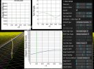
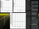
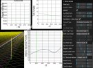
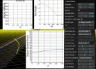
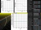
- the incredibly coincidental straight line is not incredibly straight/levelled/steady. Here it is with constant altitude in Sitrec on the left. And my reconstruction on the right, I find the same need for acceleration (from 250 to 380 Knots, average 320), to catch up with the lines of sight.


I'll note two things :
- the close trajectory was seen on SA, to go with your analogy it's like if you have an employee from the card factory telling you he's seen somebody shuffling the cards out of the machine. You can of course not trust him.
- the incredibly coincidental straight line is not incredibly straight/levelled/steady. Here it is with constant altitude in Sitrec on the left. And my reconstruction on the right, I find the same need for acceleration (from 250 to 380 Knots, average 320), to catch up with the lines of sight.
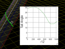
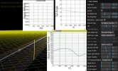
And if you want to have some sort of linear decrease in tail angle to explain the linear change in glare shape/size, it's even more difficult to find a straight line. You can of course make all kind of speculations on how a glare would or would not change linearly with tail angle.