Oroville Dam Spillway Failure

Status
Not open for further replies.
You can see from the daily incident update how the outflow is divided by the spillway and the Hyatt powerplant. http://www.water.ca.gov/news/newsreleases/2017/032217_incident_update.pdf

Thanks, I see that now:
Situation.jpg
It would seem that managing the outflow is a tricky exercise in ensuring that the Hyatt plant is not backed up while the flow over the spillway is maintained at a level that does not result in further erosion of the remaining upper section. 40,000 cfs over the spillway is what I understood to be DWR's minimum flow to avoid such erosion.
 
Nor have I been able to confirm whether the outflow continues to be a combination of the spillway and Hyatt power plant. In any case, the outflow over the spillway has been significantly less than the 50,000 cfs it was originally ramped up to.

Here is this morning's incident update as well as the others mentioned below.

Today 3/22/17: 40,000cfs is coming from the spillway and about 5200cfs is coming from Hyatt.

Yesterday 3/21/17: 40,000cfs was coming from the spillway and 5525cfs was coming from Hyatt.

3/20/17: 40,000cfs was coming from the spillway and 6450cfs was coming from Hyatt.

3/18/17: 41,500cfs was coming from the spillway and 7550cfs was coming from Hyatt.

3/17/17: at the time of the press release, 40,000 cfs were coming from the spillway and Hyatt was shut down. That night flows from the spillway peaked at 50,441cfs and then we're dropped before the Hyatt power plant was restarted the morning of the 18th.

CDEC outflow: http://cdec.water.ca.gov/jspplot/js...017+09:15&geom=huge&interval=5&cookies=cdec01Screenshot_2017-03-22-09-57-16.png
 

Attachments

  • Incident Update 032217.pdf
    129.3 KB · Views: 654
  • Incident Update 032117.pdf
    129.3 KB · Views: 748
  • Incident Update 032017.pdf
    128.3 KB · Views: 659
  • Incident Update 031817.pdf
    128.3 KB · Views: 628
  • Incident Update 031717.pdf
    129 KB · Views: 683
Reservoir level is only inching down at the moment:
Outflow22_3_17.jpg
The reduction is at a much slower rate than it was up to yesterday. (Source: http://cdec.water.ca.gov/cgi-progs/queryF?s=ORO&d=22-Mar-2017+08:36&span=12hours)

While the main spillway has not yet been running for a full week, it looks like it will be necessary to keep it running for more than the 5-6 days DWR originally anticipated would be needed to reduce the level from 864 feet to 838 (see the press briefing video above in post #1442 starting at the 5 minute mark).

That is extra use of the reinforced area of the spillway deck but to date there is no obvious sign of further erosion.

Not sure what accounts for the fairly significant increases in inflow, which have mostly occurred over the last 24 hrs. Nor have I been able to confirm whether the outflow continues to be a combination of the spillway and Hyatt power plant. In any case, the outflow over the spillway has been significantly less than the 50,000 cfs it was originally ramped up to.
Look at the column entitled 'Rain', it looks like ~2" of rain fell.
 
Wow. Uh oh. Have a look at this, which confirms some concerns voiced a while back on this forum:

http://www.sacbee.com/news/state/california/water-and-drought/article140390898.html

I think I might have understated that. If you are interested in the subject of the spillway failure, by all means have a look at the above news article.

P.S. The actual Memorandum/Report on which the article is based is attached.

Predictably it's slightly more tentative than the article but very revealing nonetheless.
 

Attachments

  • 20170317-5113(32038698).pdf
    1.3 MB · Views: 1,041
Last edited:
Above the crater, consultants described design problems in the intact portion of the chute that are so “gross and obvious” they will have to take priority this year, said J. David Rogers, a dam expert from Missouri, who reviewed the report at The Sacramento Bee’s request. Rogers said the problems the consultants described were so egregious he was surprised the spillway didn’t fail decades ago.
Content from External Source
http://www.sacbee.com/news/state/california/water-and-drought/article140390898.html#storylink=cpy

The dry conditions in Cali no doubt allowed them to get by for so long.
 
The dry conditions in Cali no doubt allowed them to get by for so long.

That makes sense although the memorandum does not discuss the effects of prolonged drought, which might include altering the clay infill that the memorandum confirms was used (see page 2 of the memo, although the depth and exact location of that infill is not described). One of the main observations in the memo is that:

"It seems likely that piping of foundation material beneath the chute slab may be responsible for the voids that have been found and repaired in the past."
Content from External Source
See page 3. This follows on the related observation that:

"The amount of drain water flowing from the pipe discharge openings along the spillway training walls seems extraordinarily large. This drainage system picks up any seepage from the herringbone system of drains under the chute slab and surface water from the backside of the training walls. It appears also that the drains are collecting leakage through cracks in the chute slab and/or defects in the construction joints between slabs. The drains appear to flow for some appreciable time after the gates are closed and no precipitation is occurring."
Content from External Source
In hindsight, it seems obvious that the truly vast void under the spillway that was revealed immediately after the deck was breached pointed to a serious deficiency in the underlying foundation material. As far as I can determine there's been next to no explanation from DWR or any other source of what "voids . . . have been found and repaired in the past."
 
Last edited by a moderator:
These Board Guys are GENIUS's! They concur completely with my determinations made weeks ago viewing videos and charts on this site from my armchair thousands of miles away. You don't often run across such smart people. :rolleyes:
 
Is there any information regarding Flood Control Spillway Gate opening size vs. flow? Are they constantly adjusting the Gates to maintain flow at a constant velocity as water level drops?
 
These Board Guys are GENIUS's! They concur completely with my determinations made weeks ago viewing videos and charts on this site from my armchair thousands of miles away. You don't often run across such smart people. :rolleyes:

Well, I suppose we can all pat ourselves on the back but looking ahead to the next stage, especially figuring out exactly what caused the failure and what could and should have been done to prevent it, the geniuses' reference to the following invites re-consideration of the spillway maintenance record:
It seems likely that piping of foundation material beneath the chute slab may be responsible for the voids that have been found and repaired in the past.
Content from External Source
I haven't found a lot in the public domain about the actual void detection and repairs carried out pre-2017 but post #1426 above makes reference to the 2009 contract for repairs at Oroville and other DWR dams. If you check the source of this at http://www.water.ca.gov/engineering/Contracts/index.cfm?Action=3, you find that in the period 2004-2016 there was only that one maintenance contract. Of course this does not mean that DWR did not do repairs themselves but I haven't found any records of what they did.

Extracted below is part of the record of the 2009 contractors' bids made and the one that was accepted, which was the lowest by a substantial margin compared with the majority of bids. Highlighted in it are the entries related to void repairs, the DWR engineers estimate of what they would cost to repair and what the successful bidder proposed as its cost. You will see that its bid came in at nearly $450,000 less than DWR's estimate and that so far as void repairs are concerned, it estimated about one-fifth of the cost DWR did:

2009_Spillway_Repair_Bid.jpg

You can find the full bid summary here: https://www.metabunk.org/attachments/09-14_summary-pdf.25791/. It discloses that other bidders' estimate of void repair costs generally ranged from slightly less or more than DWR's estimate to about three times as much. None of this discloses what was actually done either at that time or later and who by but the basis on which bids were invited was that there was 83 cubic yards of void repair required.

It's actually that number that grabbed my attention more than the bid figures. It's relatively precise and presumably reflected some investigation of foundation conditions.

However, in the abstract, "83 cubic yards" means absolutely nothing to me and so I hunted around for some comparison. With apologies for the wholly unscientific (but possibly amusing) nature of this, the number precisely corresponds to the capacity of this very handsome dump trailer, which in 2006 its makers dubbed "Monstar Scrap":
1Monstar_Scrap.jpg
That's a big trailer but its capacity looks puny compared to the scale of the void under the spillway revealed in February. Of course that's 7 years and a major drought after the 2009 repairs. If piping of foundation materials was continuing all that time the repairs, even if initially all that was really needed, seem likely to have been rendered ineffective.

FWIW, it strikes me that after 50 years of only sporadic use the fact that the main spillway was built on inadequate foundations would not necessarily be obvious to the latest generation of those charged with maintaining it, and it may be only in hindsight that its original design/construction can be seen to be seriously flawed. In other words, on the basis of what's been disclosed to date, the blame for what's happened might really lie in the relatively distant past.
 
Last edited:
was that there was 83 cubic yards of void repair required
could it have something to due with having to buy certain sizes of materials, so you pick the 'truck' that is higher than what you need. Like with dumpsters... they only come in certain sizes so you estimate what you need and sometimes you end up with extra room.

edit add; heres some that say they are 47 cubic yards like the other dam in the bid https://www.google.com/?gws_rd=ssl#q=dump+trailer+47+cubic+yerds&* ??

Typical Failure Modes for Dam Spillways Failure of dam spillways may be caused by a combination of factors. It is important to be aware of the prominent causes of failures and the telltale signs that may foretell failure. A brief description of the major causes of spillway failures is given below. FOUNDATION FAILURES – LEAKAGE AND PIPING Spillway sections are usually founded on pilings, ledge, natural soils or a combination of these materials. The effect of uncontrolled leakage through the foundation material over time can cause internal erosion of soils or deterioration of rock. The loss of foundation material from seepage forces may leave voids beneath the spillway, which decreases the overall support for the spillway. Settlement and cracking of concrete structures and the displacement of stone masonry structures may be attributable to foundation piping. https://www.des.nh.gov/organization/commissioner/pip/factsheets/db/documents/db-6.pdf
Content from External Source
 
So, during the time the spillway was not in use - we saw photos and heard reports from DWR that they were doing a full review of the upper portion and repairing any possible cracks and voids.

Review the most recently posted photos on the DWR pixel site such as this one:
upload_2017-3-25_12-30-55.png
https://pixel-ca-dwr.photoshelter.c...00czvB7nsUNwg/FL-Oroville-7963-03-23-2017-jpg

Even after repairs just completed and with, I would say, a higher level of attention to detail than previously - there is still significant flow in the under slab drainage system.
 
Page 2 of the memorandum:
"The amount of drain water flowing from the pipe discharge openings along the spillway training walls seems extraordinarily large."

This is the telling quote for me. That "extraordinarily large" flow seemed consistently evident in many of the spillway videos. There are of course those few drains that were not flowing but the overall flow showed that the spillway seemed to be leaking a tremendous amount of water. The drains that were not flowing indicated the water was likely leaving the scene by other routes. I feel that a major portion would have been soaking and flowing through the softer, more porous bed material and leaving behind voids.

That seemed to me to be so obvious that I wondered how the operating staff and the visiting inspectors could have failed to make note of it. From the wording of the report, I think the BOC felt the same way.

Given the age of the structure and that the leakage has likely increased slowly over the years, and as the operating staff was replaced by different people, the eventual state was felt to "be the way it has always been".
 
Page 2 of the memorandum:
"The amount of drain water flowing from the pipe discharge openings along the spillway training walls seems extraordinarily large."".

I agree %100... And remember, there is NO backup. The emergency spillway is rubbish. This 50 year old spillway MUST work till November, and it already failed once. This story is not over.
 
could it have something to due with having to buy certain sizes of materials, so you pick the 'truck' that is higher than what you need.

I see your point. I read the figure as relating to the area to be filled rather than the method of transporting it to the site, which in this case means the spillway deck itself.

Suppose that the material was concrete, which is what the original spillway spec called for as backfill between the deck and the underlying rock. The capacity of the average concrete mixing truck is 10 cubic yards - according to various sources, including this one:https://www.reference.com/home-garden/many-cubic-yards-concrete-truck-hold-f16ec3f128dc18d2#.

But a truck equipped with a concrete pump can deliver many times that amount per hour to the area where it is to be applied (see https://en.wikipedia.org/wiki/Concrete_pump) and would not need to be placed on the deck (even assuming it's possible to get a vehicle that large on the deck) in order to deliver it. So in this scenario the capacity of the vehicle used to transport the material would not necessarily govern how much of it the DWR thought was needed for void filling.

More generally it stands to reason that DWR have records of why they invited bids for the 2009 repairs on the basis that they did, including the (relatively limited) scale of the void repairs. I can't imagine that they have not already investigated this but it's just not part of what gets routinely released to the public - still less in circumstances where DWR's maintenance record stands to be critically examined.

One reason I come back to this is Acting DWR Director Croyle's robust defense of that record in the last press briefing - he said they'd done everything that was needed "and more." It struck me at the time that this might be inviting trouble further down the line.
 
Even after repairs just completed and with, I would say, a higher level of attention to detail than previously - there is still significant flow in the under slab drainage system.

That was the side they didn't patch up as they routed the stream of water that way. It would be interesting to see how the left side looks, but I haven't seen any photos or video of it.
 
That was the side they didn't patch up as they routed the stream of water that way. It would be interesting to see how the left side looks, but I haven't seen any photos or video of it.

You can see that there is significant flow down the left side (nearest) by looking at the bottom center right of the image I posted:
upload_2017-3-25_15-0-2.png

This pipe, providing a temporary extension of the VCP longitudinal drain, covers only the last remaining section of herringbone drains on this side and is showing plenty of output - there's no reason to believe the drains further up are behaving any differently.
 
Based on that image, versus ones I'd seen prior to shutting down the spillway, the amount of water pouring out of the drains on the side is a lot less. I don't know what is an acceptable amount, but the drains were throwing the water out pretty hard prior to shutting down the spillway and doing some sealing and repair work.

Correction: From looking back over photos where the spillway was at 50,000 cfs prior to the shutdown, it appears that there is little difference between what's coming out of the side drains before and after the repairs. I was remembering how it looked at 100,000 cfs where it was jetting out of the drains with some pressure behind it.

So, during the time the spillway was not in use - we saw photos and heard reports from DWR that they were doing a full review of the upper portion and repairing any possible cracks and voids.

Review the most recently posted photos on the DWR pixel site such as this one:
upload_2017-3-25_12-30-55.png
https://pixel-ca-dwr.photoshelter.c...00czvB7nsUNwg/FL-Oroville-7963-03-23-2017-jpg

Even after repairs just completed and with, I would say, a higher level of attention to detail than previously - there is still significant flow in the under slab drainage system.
 
Last edited:
So, during the time the spillway was not in use - we saw photos and heard reports from DWR that they were doing a full review of the upper portion and repairing any possible cracks and voids.

. . . Even after repairs just completed and with, I would say, a higher level of attention to detail than previously - there is still significant flow in the under slab drainage system.

That and the fact that the flow out of the drains continues after the spillway has run makes you wonder where the influx of water is coming from - as in whether there is an underground flow from the area of the gate structure.

But no one has suggested that; what the Board has said, however, is that the upper part of the spillway leading back to the gate structure needs to be replaced. This is from the last section of the memorandum, which also bears on the short-term measures to "bridge" the area of the waterfall/crater/splash pool (underlining in point 3 below added):


  1. M1–2.1 Extensive efforts are underway to locate and repair any voids beneath the upper chute slab and patch any spalls and seal cracks or joints that permit water to enter the under-drain system. The BOC concurs that this work needs to be completed on a priority basis.

  2. M1–2.2 The BOC is of the opinion that a temporary end of chute paving could be configured with a small flip angle to throw the discharge a distance downstream where it might impact on the remaining paved chute near the existing flip bucket.

  3. M1–2.3 Interim measures to address any voids beneath the slab, repair spalls and deteriorated concrete and to caulk all open cracks and joints are planned. The existing training walls will be anchored to improve their stability and strength. The BOC agrees that these measures should be accomplished as an interim solution. The complete replacement of this section of the chute should be scheduled as part of the work during the second season.

  4. M1–2.4 Another alternative for repair of this upper chute section is to anchor a reinforced concrete overlay on top of the existing slab as a permanent fix. In the BOC’s opinion this solution leaves too many unknowns unanswered as to the foundation conditions beneath the existing slab.
Content from External Source
 
Looking at the photo at the top of #18, it looks possible that the softer brown material eroded away from underneath the spillway, becoming semiliquified as the soil saturated with water. This would create a void where the spillway was not supported from underneath, leading to the failure.
A panel of outside experts partially confirmed the observation/guess I made last month.

Notably, the panel expressed concern that the concrete chute is only a foot thick, and less so in some places. DWR built the spillway on an uneven mountainside and in some spots used compacted clay to fill in the depressions in the rock foundation beneath the concrete. The consultants described finding evidence of “a number of repair instances” in which portions of the chute were cut away in order to “fill voids beneath the concrete.”

“This calls into question whether the portions of the slab that appear undamaged by the failure should be replaced during the restoration,” the panel wrote.

Rogers said the structure probably needs to be rebuilt from the ground up.

“I was shocked to hear the slab is only 12 inches thick, and that there’s clay pockets underneath it,” he said. “That section is going to have to be ripped up and you’re going to have to start over again, most likely.” He added that “it’s remarkable it lasted as well as it did.” He said he’s surprised the structure didn’t fail after the winter of 1997, when officials cranked up releases to their highest-ever amounts.

Paul Tullis, a dam safety consultant from Utah who reviewed the panel’s report for The Bee, agreed that it found the original design and construction inadequate.


http://www.sacbee.com/news/state/california/water-and-drought/article140390898.html

Content from External Source
This was in the Sacramento Bee. I haven't been able to pull up the original report. The most ominous part is they don't think it could be fixed in one season.
 
Last edited by a moderator:
The most ominous part is they don't think it could be fixed in one season.

Typically it's only used every few years, there's a very good chance it would not be needed next year - especially if they keep levels low via the power station outlets (and the other valved outlets).

However it would just take a couple of solid pineapple expresses to fill it up. So there's no guarantees.
 
DWR must plan for the use of the spillway next year. You just don't know what the weather will be. This is the same reason why every year the prudent man would carefully examine the spillway and fill all voids and cracks, fix the drainage system, etc.

If the main spillway can't be completely fixed in one year, it just makes the job more expensive.

Any additional or necessary permanent fixes to the emergency spill can be done this year.
 
DWR must plan for the use of the spillway next year. You just don't know what the weather will be.

Absolutely, just from a planning perspective there's a difference between 100% possible and 5% possible. They certainly need a plan for all possible weather outcomes.
 
Typically it's only used every few years, there's a very good chance it would not be needed next year - especially if they keep levels low via the power station outlets (and the other valved outlets).

However it would just take a couple of solid pineapple expresses to fill it up. So there's no guarantees.
e

The spillway flowed in March, 2016, a year when precipitation was 16% above normal according to CDEC. Before that, not since 2011. http://www.abc10.com/news/local/cal...illway-for-first-time-in-five-years/101137863
2010 was also very wet year. 2007, 2008 and 2009 were dry. So I am guessing the spillway was used four years in the last 11. The maximum drainage at the bottom is approximately 15,000 cfs. Shasta Dam can drain more than 70,000 CFS from the bottom.
 
Looks like, the Spillway has been shut-down and the Power Plant is running full-out. Pictures would be helpful. Unfortunately, they closed the Spillway around Dusk. Also the Inflow is increasing.

In the DWR press briefing yesterday (video here: https://www.facebook.com/CADWR/videos/10154555376317449/) it was announced that over the afternoon the spillway would be shut down, as has happened, and five turbines at the power plant are running (video starting at 13 min. mark). A few points of note from the briefing are listed below.

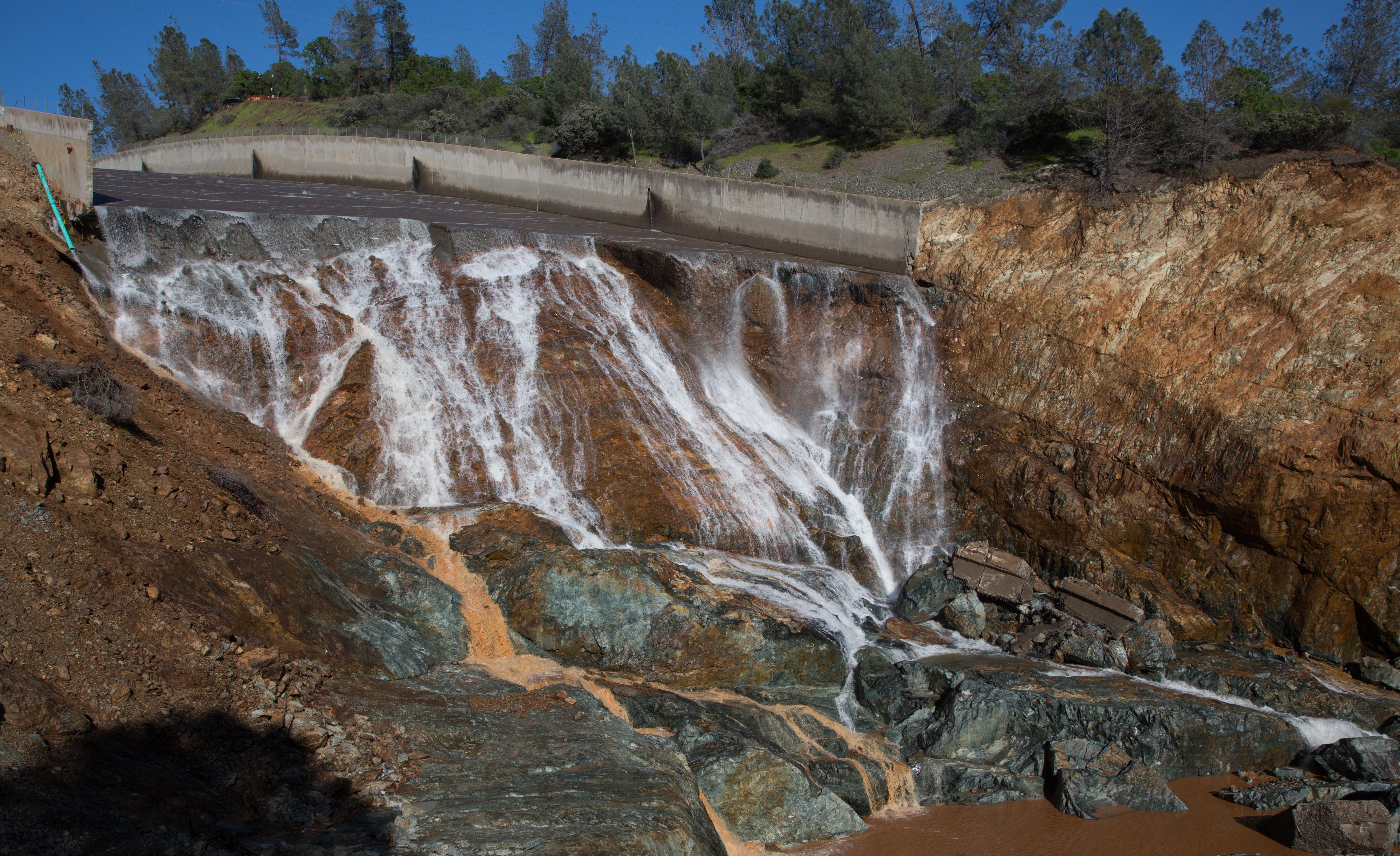
As of today some new photos of the post-shutdown state of the spillway were posted in the DWR photo gallery: https://pixel-ca-dwr.photoshelter.c...g/G00003YCcmDTx48Y/Oroville-Spillway-Incident. The close-up posted above indicates that the shotcrete placed at the damaged end of the upper part of the spillway has held up. This shot also seems to show no further headward erosion in the remaining upper spillway deck:
DK_oroville_spillway_7349_03_27_2017.jpg

Salient points from the briefing (Mr Croyle's commentary starting at 18 mins.):
  • Although the design criteria for the immediate/long-term recovery of the spillway is not final (but will be announced very soon), the likelihood (judging from Croyle's remarks) is that it will be a rock and concrete-based structure. He mentioned placing a rock crushing and concrete batching plant on site. See also the extract from the Board of Consultants Memorandum copied below.
  • Several design options have been considered, including bridging the eroded area with steel or concrete beams. But by the sound of it the preferred option is basically to use rock/concrete as the support for a reconstructed spillway deck.
  • Mr Croyle was really adamant the there would be a functioning main spillway in place by November even if it is only a partial and/or temporary structure. Use of the emergency spillway is not completely ruled out.
The preferred repair option seems to have been determined on the basis of the Consultants' Memo, which noted the following (at pages 4-5):


Restoring the original spillway will require that the entire lower section of the chute training walls and flip bucket be rebuilt. Whether this can be completed in the short time period until November is questionable. It would require rebuilding the foundation for the chute slab and walls in the deeply eroded holes with concrete. This seems likely to be done using conventional concrete in the bottom of the depressions to obtain a level surface to place Roller Compacted Concrete (RCC) up to the foundation level. The reinforced concrete chute slab and training walls would then be placed starting at a connection to the existing upper chute. The BOC questions if this can all be completed before November. The BOC is of the opinion that a temporary end of chute paving could be configured with a small flip angle to throw the discharge a distance downstream where it might impact on the remaining paved chute near the existing flip bucket. This would be used only for one flood season. Some additional downstream erosion should be expected and would be considered acceptable. During the next construction season, this portion of the chute would be completed.
Content from External Source
 
Last edited:
Screenshot from the 1:20 mark, showing flows at 4:45pm yeaterday, when it was reduced to about 30,000cfs. Looks like a fair amount of brown erosion happening at that lower flow.

Slightly larger views below of the same area in the same 15 period of time to which this part of the video relates. Viewed side on it practically looks like material is being piped out from somewhere under the spillway and there are loose rocks visible that the flow is propelling out over the water:

Image1-1-20.png

Not long afterwards in the video (1min:32 secs. mark and 1:38) there are overhead views that also show this particular area of erosion although it may be wider and further downstream from the grouted area under the spillway (the edge of which is clearly visible in these views) than the first image suggests:

Image2-1-32.png Image3-1-38.png
 
Regarding the bid for 83 cubic yards of concrete for earlier repairs:

could it have something to due with having to buy certain sizes of materials, so you pick the 'truck' that is higher than what you need. Like with dumpsters... they only come in certain sizes so you estimate what you need and sometimes you end up with extra room.

... and only in the interest of providing some general info about that idea:

Concrete trucks typically carry 10 cubic yards, as pointed out by Boilermaker in his reply about this, but the reason for that is that such trucks are very near the legal load limit for their number of axles and axle spacing. The actual regulations regarding axle loads are quite involved and not really worth quoting in detail for the purpose of this relatively minor point, but anyone who wants to work out the details for California roads can do so using info such as this.

http://www.dot.ca.gov/trafficops/trucks/weight.html

Then considering that an average density for concrete is roughly 4,000 pounds per cubic yard,

https://en.wikipedia.org/wiki/Properties_of_concrete

Tests can be made to ensure the properties of concrete correspond to specifications for the application. The density of concrete varies, but is around 2,400 kilograms per cubic metre (150 lb/cu ft).
Content from External Source
... if we were to assume a moderate allowable load of 34,000 pounds per each group of multiple axles on a truck (this figure was picked from the load-regulations site linked above, and chosen because of the moderate axle spacing associated with it) , carrying 83 cubic yards of concrete would require the truck to have 10 groups of axles with the number of axles per group being not less than two. So in this example, the truck would need 10 tandem-axle sets (perhaps "only" 9 sets if a single steering axle could be rated to carry the leftover weight), which is far in excess of what you'll see on any normal truck. This can only be considered an approximation of course, given how the axle loading was chosen, but at least it illustrates that carrying 83 cubic yards in one batch would require a very unusual truck.

That semi-trailer with the 83-cubic-yard capacity illustrated by Boilermaker, had one tandem-axle set for the trailer and presumably one more for the tractor, plus a steering axle, so it would only be suitable for carrying low-density materials, and I believe he showed that picture just to give us a sense of scale regarding the necessary volume of material.

Edit: I overlooked something important. I ignored the weight of the truck and that amplifies the problem which I tried to illustrate even more. I'm not sure why I'm having so much trouble finding an official source stating the weight of an average 10-yard mixer truck, but here's a site that says 26,000 pounds, and a truck designed to carry a lot more than 10 yards would have a substantially greater curb weight.

https://www.reference.com/vehicles/much-concrete-mixer-truck-weigh-4336f32d54cf0931


Q:
How much does a concrete mixer truck weigh?
A:
Quick Answer

Cooper Concrete calculates that an unloaded concrete mixing truck with a capacity of 10 cubic yards weighs approximately 26,000 pounds. A loaded truck of the same size can weigh as much as 66,000 pounds.
Content from External Source
 
Last edited:
Slightly larger views below of the same area in the same 15 period of time to which this part of the video relates. Viewed side on it practically looks like material is being piped out from somewhere under the spillway and there are loose rocks visible that the flow is propelling out over the water:
It's difficult to be sure, but it appears to me that the eroded material that shows up in that photo is coming from the location where the water shooting off the slab first splashes against the substrate. We'll know which is the case as soon as new photos reveal whether or not there's a gaping hole at that location within the embankment right below the edge of the slab.
 
It's difficult to be sure, but it appears to me that the eroded material that shows up in that photo is coming from the location where the water shooting off the slab first splashes against the substrate. We'll know which is the case as soon as new photos reveal whether or not there's a gaping hole at that location within the embankment right below the edge of the slab.

Below is one of DWR's latest pictures of that section of the spillway. It's really not possible to tell if the flow of eroded material is coming from under the spillway (possibly through a hole in or under the shotcrete) but it seems odd that there is so much material in that one place.
7295_03_27_2017.jpg

As an afterthought, I suppose that if this was material coming from under the spillway rather than the bank in front of it, it might have been seen before the point at which the flow was reduced such that it was falling on that bank rather than shooting over it. On that basis the explanation quoted above is probably more likely to be right than this being evidence of water getting through the spillway deck despite all the recent caulking of it and flushing out material from underneath.
 
Last edited:
Below is one of DWR's latest pictures of that section of the spillway. It's really not possible to tell if the flow of eroded material is coming from under the spillway (possibly through a hole in or under the shotcrete) but it seems odd that there is so much material in that one place.
7295_03_27_2017.jpg
As an afterthought, I suppose that if this was material coming from under the spillway rather than the bank in front of it, it might have been seen before the point at which the flow was reduced such that it was falling on that bank rather than shooting over it. On that basis the explanation quoted above is probably more likely to be right than this being evidence of water getting through the spillway deck despite all the recent caulking of it and flushing out material from underneath.
If you look at the pictures with the water off (such as the one from your earlier post quoted below), it looks to me like there was a high spot in the dirt/rock right about where that stream of mud is coming from:
As of today some new photos of the post-shutdown state of the spillway were posted in the DWR photo gallery: https://pixel-ca-dwr.photoshelter.c...g/G00003YCcmDTx48Y/Oroville-Spillway-Incident. The close-up posted above indicates that the shotcrete placed at the damaged end of the upper part of the spillway has held up. This shot also seems to show no further headward erosion in the remaining upper spillway deck:
DK_oroville_spillway_7349_03_27_2017.jpg
At higher flows, the water goes out far enough to miss it (see around 0:20, or 0:47) but (as shown in the video that Anna Reynolds posted) at low flows, the water seems to be surging or coming down in waves, so as it varies how far it arcs out, it sweeps the whole area from the shotcrete out (starting at 1:15 in the video):

Source: https://youtu.be/ixTg5Tgzeus

Aaron Z
 
Regarding the bid for 83 cubic yards of concrete for earlier repairs:


... and only in the interest of providing some general info about that idea:

Concrete trucks typically carry 10 cubic yards, as pointed out by Boilermaker in his reply about this, but the reason for that is that such trucks are very near the legal load limit for their number of axles and axle spacing. The actual regulations regarding axle loads are quite involved and not really worth quoting in detail for the purpose of this relatively minor point, but anyone who wants to work out the details for California roads can do so using info such as this.

http://www.dot.ca.gov/trafficops/trucks/weight.html

Then considering that an average density for concrete is roughly 4,000 pounds per cubic yard,

https://en.wikipedia.org/wiki/Properties_of_concrete

Tests can be made to ensure the properties of concrete correspond to specifications for the application. The density of concrete varies, but is around 2,400 kilograms per cubic metre (150 lb/cu ft).
Content from External Source
... if we were to assume a moderate allowable load of 34,000 pounds per each group of multiple axles on a truck (this figure was picked from the load-regulations site linked above, and chosen because of the moderate axle spacing associated with it) , carrying 83 cubic yards of concrete would require the truck to have 10 groups of axles with the number of axles per group being not less than two. So in this example, the truck would need 10 tandem-axle sets (perhaps "only" 9 sets if a single steering axle could be rated to carry the leftover weight), which is far in excess of what you'll see on any normal truck. This can only be considered an approximation of course, given how the axle loading was chosen, but at least it illustrates that carrying 83 cubic yards in one batch would require a very unusual truck.

That semi-trailer with the 83-cubic-yard capacity illustrated by Boilermaker, had one tandem-axle set for the trailer and presumably one more for the tractor, plus a steering axle, so it would only be suitable for carrying low-density materials, and I believe he showed that picture just to give us a sense of scale regarding the necessary volume of material.

Edit: I overlooked something important. I ignored the weight of the truck and that amplifies the problem which I tried to illustrate even more. I'm not sure why I'm having so much trouble finding an official source stating the weight of an average 10-yard mixer truck, but here's a site that says 26,000 pounds, and a truck designed to carry a lot more than 10 yards would have a substantially greater curb weight.

https://www.reference.com/vehicles/much-concrete-mixer-truck-weigh-4336f32d54cf0931


Q:
How much does a concrete mixer truck weigh?
A:
Quick Answer

Cooper Concrete calculates that an unloaded concrete mixing truck with a capacity of 10 cubic yards weighs approximately 26,000 pounds. A loaded truck of the same size can weigh as much as 66,000 pounds.
Content from External Source

Here is an ad for a 5 axle 2016 Mack GU713 truck with an 11 yard concrete mixer installed. It has a GVWR of 66,000# per the ad: http://www.brucknertruck.com/NewTrucks-Mack-GU713-39591
MackCementmixer.PNG
Based on the ad and the pictures, it appears to have a 20,000# GVW front axle, two 23,000# GVW drive axles, a pusher" liftable axle in front of the drives that is rated for 13,200# and a "stinger" (flip down axle in the back) that is probably rated for another 13,200# (plus it helps with the bridge calculations because it adds to the length of the rear axle set)
So it has about 92,000# worth of axles under it, but it can legally gross 66,000# on the road (unless it has an overweight permit which is possible, the it might be able to gross more (especially on state roads) depending on how that is setup).

It is interesting to see the difference between the various states as in NY a properly setup straight truck (20k front axle, 3 23k axles in the back, a 13k steerable lift axle between the rear group and the front axle and an overweight permit) can gross 80k driving down the road.

Aaron Z
 
Concrete trucks typically carry 10 cubic yards,
I thought 'rip rap' meant like dumping gravel then concreting like they did on the emergency spillway. maybe someone could write the company and ask them how they filled the voids.
 
I thought 'rip rap' meant like dumping gravel then concreting like they did on the emergency spillway. maybe someone could write the company and ask them how they filled the voids.
Riprap is generally just good sized rock, the testing that the US Bureau of Reclamation did (for riprap to use to armor a dam in an area that will be overtopped) used rock ranging from ~2" to ~24":
Pages 3-4 of https://www.usbr.gov/tsc/techreferences/hydraulics_lab/pubs/PAP/PAP-0790.pdf

Tests were first conducted in 1994. The first test section consisted of large riprap with
D50 of 386 mm placed 0.6-rn-thick over a 203-mm-thick gravel bedding material. The riprap
was selected based upon extrapolation of previous design equations [2]. The bedding layer
thickness and size were designed according to standard Reclamation criteria.
The riprap tests performed in 1995 utilized the first test bed with a second, 0.6 m thick
layer of relatively uniformly graded rock with D50 of 655 mm, placed over the existing material.
Most rocks were dumped into the flume; however, because of the rock size, some hand
readjustment was necessary to even out the surface and avoid damaging the instrumentation.
The bedding and riprap material from the previous tests basically became the bedding material
for the larger riprap of the 1995 tests.
Content from External Source
If we go back to post 1444, Boilermaker's combined picture shows an excavator placing large riprap on the bank opposite where spillway dumps into the channel:
This might answer your question. Below are photos from the DWR "Oroville Spillway Incident" page (https://pixel-ca-dwr.photoshelter.c...g/G00003YCcmDTx48Y/Oroville-Spillway-Incident)
In addition, from the same source I have stitched together this panorama, which is intended to show the construction of the rock bank opposite where the water actually comes off the spillway. I am not sure if the perspective is right/the two photos were take from the same vantage point but you get the general idea of the reinforcement put in place where the water enters the channel:
3_Panorama.jpg

If they were placing riprap under the spillway, they most likely did like they did for the emergency spillway armoring and placed rocks, then poured concrete over the top of them (perhaps with a layer of smaller gravel on top of the riprap to use less concrete and let water flow through the riprap?).

Aaron Z

Aaron Z
 
Status
Not open for further replies.
Back
Top