NYT: GIMBAL Video of U.S. Navy Jet Encounter with Unknown Object

The object is definitely moving as the pilot describes, right? In an interview with BBC's Rhod Sharp, Elizondo says the object simultaneously decelerates to a dead stop and performs the rotation:
http://www.bbc.co.uk/programmes/b09jcpvz#play
@13:30
What you're seeing is an object that is in a 120 knot head wind [with] a field around it... and it comes to a complete stand still at a perpendicular angle even though there's a 120 knot head wind.
Content from External Source

Not necessarily. It's looks like it's moving relative to the clouds, but that could simply be parallax from the motion of the jet.

It's nonsensical he says there's a "field" around it, as that's just an IR artifact. You can pretty much discount anything else he says that's just his opinion.
 
The appearance of the target slowing down corresponds to the azimuth to it approaching 0˚, ie, to the target becoming straight ahead. So the appearance of it slowing down is almost certainly another optical illusion.
 
Last edited:
I've updated my schematic for the 'two-camera' hypothesis, incorporating the gimbal housing...


So a lens flare could be caused by the housing window and/or any lens in the gimbal camera. As Mick noted before, this conjectural modeling might just be compatible with the complex internal optics of the ATFLIR system, which seems to be segregated into two sets of optical components, with the rear set almost certainly outside the rotatable globe-shaped gimbal housing...


Also (for those who may just be joining), I confirmed that one camera rotating while being recorded by a second camera held static to the user can exactly reproduce the appearance of a lens flare rotating freely against a stable scene


which is exactly what we observe in the F18 insurgents video


and theoretically exactly what we observe in the gimbal video. Thinking about it, if you want to have a gimbal camera that can move freely to track any target and you also want that system to output a scene that is continuously held stable to the pilot, it seems you actually must have a 'two-camera' set up like this.
 
Last edited:
it seems you actually must have a two-camera set up like this.

That would be a very inelegant solution.
If you can record an image on screen with a camera why not record , for instance an optical image at the same point. The "common optical path" video is not intended to give away much. The laser seems to be fixed behind the pivots and needs to be automatically centred in the camera centre. They could possibly do this by detecting the beam by one of the cameras, eg using a chopper and a servo system, or by some clever optical geometry, involving, say, a retro-reflector, but it sheds no real light on the camera arrangement.
 
Clouds Givemethewillies, as I made clear previously, I'm using 'camera' kind of figuratively, it would be two sets of lenses and such where each would be sufficient to be a camera. I don't understand how what you say differs. But if you have another design, how about demonstrate it. I've demonstrated what I'm proposing above, and the result is a dead match of the F18-insurgents video.
 
Virtual cameras might help some people, but as a simple soul, it confuses me. The window (and possibly some other components) rotates relative to the frame of reference of the plane, which also corresponds to that of the display, so how the system is implemented is largely irrelevant to the rotation observed.
 
That's assuming they have no technology in place which makes them automatically invisible/blurry when photographed...

Well, those particular "alien" UFOs did NOT have technology which rendered them invisible to radar or optics. If they did, there would have been no sighting and no discussion. The 2004 Nimitz "UFOs" were detected many times on radar by the USS Princeton's SPY-1a radar system. In fact that's how the F-18s were vectored there.

Fortunate for the aliens, that was in 2004. Today it's possible the WSO might say "Dude, let me get out my Nikon P900 with an optically stabilized 83x zoom, and we'll get a clear shot of that thing".

....Are our militaries working on exactly the same sorts of technology? Of course...

The US military already *has* the technology to stealthily observe targets without being detected. As opposed to the dumb aliens, if the military wanted detailed imagery of an area they'd take it with an optical spy satellite from orbit, or a synthetic aperture radar imaging satellite using antenna arrays the size of a football field, which can resolve objects with 12 inch resolution at night through clouds: https://en.wikipedia.org/wiki/Orion_(satellite)

Or the military would use a stealth drone which cannot be detected on radar, or a fleet of surveillance nano robotic drones disguised like birds or insects:
Source: https://www.youtube.com/watch?v=SgxtIPIDBnY


Or they would just tap our telecom trunks like the NSA does and collect all the info they wanted.

It is interesting that alleged star-faring aliens don't seem to have this technology. They are seen joy-riding in the atmosphere at slow speed like a barnstorming daredevil from the 1930s, as if looking out their windows with goggles and scarf trailing in the wind.

It therefore seems much more likely the Gimbal and "Tic Tac" UFOs are of earthly origin and only seem mysterious due to the blurry fuzzy nature. If they were really aliens we'd probably never see them.
 
Since we have never found any conclusive evidence for extra terrestrial life (certainly not any intelligent), the question what some hypothetical aliens can or can not do, or what they would want to do or not, is so open that it is pointless to speculate. I mean, why would they even care if we saw them? I'm sure you could come up with all kinds of reasons but it would just be science fiction.

If TTSA had some real evidence of aliens, why only release this fuzzy video with dramatic dialogue added? Why can't the media interview the pilots (in this gimbal case) ? Why isn't the entire FLIR video released? Why isn't radar data and other relevant data also available? Why not interview/hire experts on this ATFLIR pod and see what their conclusion is. And so on. It doesn't seem like they are even trying to convince anyone who isn't already a believer, just trying to get the believer camp to fund their new media company.

Or in the words of astrophysicist Neil deGrasse Tyson:
It seems to me aliens that visited us, they would manifest more convincingly than fuzzy video. There is no reason to assume that because you don't know what you are looking at it equals aliens from outer space.
Content from External Source
I suspect if the videos weren't fuzzy, the flying object wouldn't be unidentified anymore, and dismissed either as a hoax or as something mundane.

 
That would be a very inelegant solution.
If you can record an image on screen with a camera why not record , for instance an optical image at the same point.

Now I think I understand your point and it is what I am proposing. I updated my post to add quotes around 'camera' so as to try to make clear I'm not talking about a handheld camera with display screen in the pod being recorded by another handheld camera, exactly as in my demo and possibly inferred from my simplified diagram. I'm talking about an optical image output from the first gimbal camera being taken up by a second user-stabilized camera.
 
Someone posted this video of another EO/IR pod, the ASELPOD, to my video, saying it demonstrates that the ATLFIR pod camera cannot rotate free of the housing window in front of it. This video is worth it by itself for giving some close-up insight into a similar optical gimbal system:


However, I think I do see housing-independent camera movement that I cropped out and slowed down here:


The independent motion of the camera looks at least like you'd expect from a gimbal camera, but might also be more than that. Seems to me when the camera lens faces us directly it's perfectly parallel to the housing window, but then as the housing rotates upwards, the camera seems to rotate upwards even faster. Of course this isn't even the ATFLIR system, so the objection takes a big leap to infer the mechanics of the ASELPOD to that of the ATFLIR pod.

Watching that housing rotate really underscores how you must have a secondary camera system to stabilize the final output to the user. A pilot simply could not comprehend the direct output of such a gimbal camera spinning all around! And in that case, with a 'two camera' system, the window can stay tightly bound to the lens behind it and the system will still produce a flare rotating around in a stable scene.
 
Last edited:
...Watching that housing rotate really underscores how you must have a secondary camera system to stabilize the final output to the user. A pilot simply could not comprehend the direct output of such a gimbal camera spinning all around! And in that case, with a 'two camera' system, the window can stay tightly bound to the lens behind it and the system will still produce a flare rotating around in a stable scene.

That is correct. If the image was not stabilized and oriented with respect to the horizon, it would be useless to the pilot. If the ATFLIR system does not physically maintain orientation on the first optics, it is nonetheless achieving that down the chain some other way.

Here is camera feed and in-cockpit footage (starting at 01:12) of the former F-14 TCS system. It was visible light, not IR but much higher resolution and magnification than ATFLIR. It was a stabilized Cassegrain telescope specifically designed for visual identification of targets far outside normal eyeball range. In this sequence it is slaved to the radar system so automatically tracks the incoming opponent.

Fortunate for the Gimbal and Tic Tac UFOs, there was no F-14 close by or (a) We'd be looking at the rivet heads on their alien vehicle, or (b) It would show a mundane earthly vehicle hence no mystery.


Source: https://www.youtube.com/watch?v=PhuOPJ5pWsU
 
Just to add a bit more to the case. What happens optically can be compared to the so called "nasmyth focus" in astronomical telescopes. For any scientific instrument mounted on this position, a "de-rotator" needs to be used to rectify the (rotating) stellar field. It it a fully optical unit, that uses multiple mirrors.
 
This GIF animation compares the rotation of the target to the ATFLIR camera's line-of-sight (LoS) to it as given in the screen data. This will load slow on the first run, and then it runs the entire gimbal clip at 3x speed.


Target rotation seems compatible with gimbal-system adjustments as the target approaches LoS = 0˚.

Here is a simple check: If the target is 2 degrees. below the main forward facing axis, the window should rotate 90 degrees. for a target moving +/- 2 degrees. left to right. (tan-1(2/2) = 45 degrees, * 2)
 
Here is a simple check: If the target is 2 degrees. below the main forward facing axis, the window should rotate 90 degrees. for a target moving +/- 2 degrees. left to right. (tan-1(2/2) = 45 degrees, * 2)

I don't think so. The amount that needs to be rotated depends on the orientation of the first axis of rotation of the window.
8#) * 2018-01-05 14-01-12.png
If this is oriented more vertical than less rotation would be needed on the second axis (along the tube).
 
I don't think so. The amount that needs to be rotated depends on the orientation of the first axis of rotation of the window.
8#) * 2018-01-05 14-01-12.png
If this is oriented more vertical than less rotation would be needed on the second axis (along the tube).
I don't follow. Frames of reference can be tricky. I suppose I am assuming that the aircraft and pod longitudinal axes are parallel, or when they say aircraft axis they really mean pod axis..
Even if the aircraft is banked, "down" and "side" are still orthogonal, so the resultant vector and its rotation (corresponding to optical axis) is still the vector sum of the two orthogonal components. I guess I am missing something.
 
Last edited by a moderator:
I don't follow. Frames of reference can be tricky. I suppose I am assuming that the aircraft and pod longitudinal axes are parallel, or when they say aircraft axis they really mean pod axis..
Even if the aircraft is banked, "down" and "side" are still orthogonal, so the resultant vector and its rotation (corresponding to optical axis) is still the vector sum of the two orthogonal components. I guess I am missing something.

Maybe not. I was thinking that the first axis would be more vertical like:


But with that there's no way for it be be at 0° forward and 2° down. A downward tilt with the window pointing forwards requires something other than twist along the long axis. So a simple orientation change would need the 90° move. But here we are getting into gimble lock - what happens if the camera is at 0.1° down, or 0.0001°?

It's a bit head hurting, really needs a proper 3d visualization, but then it is hard because we don't know the mechanics of what is behind the glass.
 
Maybe not. I was thinking that the first axis would be more vertical like:

But with that there's no way for it be be at 0° forward and 2° down. A downward tilt with the window pointing forwards requires something other than twist along the long axis. So a simple orientation change would need the 90° move. But here we are getting into gimble lock - what happens if the camera is at 0.1° down, or 0.0001°?

It's a bit head hurting, really needs a proper 3d visualization, but then it is hard because we don't know the mechanics of what is behind the glass.

For very small motions, there are fast steering mirrors (FSM). But yeah, that's why it rotates 90 degrees when staring forward. It's designed more for air-to-ground than air-to-air.

Edit: By the way, don't assume that the line of sight is orthogonal to the big window. It may be orthogonal to the small window of the Laser Spot Tracker. There's a picture of it without the glass on SPIE.
http://dx.doi.org/10.1117/12.668385
 
Last edited:
Edit: By the way, don't assume that the line of sight is orthogonal to the big window. It may be orthogonal to the small window of the Laser Spot Tracker. There's a picture of it without the glass on SPIE.
http://dx.doi.org/10.1117/12.668385

They can't both be right, and tilted windows are good from a reflection point of view, so they are probably both tilted. For lasers windows are also normally wedged because of interference effects. The rotation of artefacts is probably unchanged as a result of the tilt, however.
 
Last edited:
For very small motions, there are fast steering mirrors (FSM). But yeah, that's why it rotates 90 degrees when staring forward. It's designed more for air-to-ground than air-to-air.

Edit: By the way, don't assume that the line of sight is orthogonal to the big window. It may be orthogonal to the small window of the Laser Spot Tracker. There's a picture of it without the glass on SPIE.
http://dx.doi.org/10.1117/12.668385

Great find! The Roll Drive Unit behind the gimbal housing may be an important rotational driver, and having to keep both camera and laser windows continuously facing the target might require adjustments as the LOS changes. That is clearly indicated in that paper. Quoting therefrom:

The targeting FLIR, EO sensor, laser rangefinder and target designator share a common optical path with continuous automatic boresight alignment. This design approach minimizes boresight errors between the sensors and laser lines of sight (LOS) and is key to the ATFLIR's performance improvement over previous systems. [...]

The Roll Drive Unit provides 360 degrees continuous roll, which enables the F/A-18 aircrew to persistently observe threats regardless of flight maneuvering. This capability also increases the system survivability.

The target tracker acquires and tracks ground and air targets. The tracker and servo controller actuate motors in the EOSU and the Roll Drive Unit to point the common optical path LOS at the target. The target tracker and servo controller keep the system pointed at the target for imaging and target designation automatically, without pilot intervention.

ATFLIR can also track targets designated by ground forces or another aircraft using the Laser Spot Tracker (LST). The LST is integrated into the EOSU. It senses the laser spots designated by ground forces or another aircraft and provides information to the ATFLIR tracker and control so that the common optical path LOS can be pointed automatically at the designated spot.

This is a good copy of Figure 3 therein appearing directly below that text (albeit with Chinese charters superimposed, sorry), note the Roll Drive Unit location:


So rotational adjustments may be affected by the Roll Drive Unit to keep both camera and laser optics simultaneously facing the target. We've only been thinking of the camera and its window, but there are two windows on the gimbal housing and the system keeps both simultaneously facing the target. This adds a highly likely reason for needing to make rotational adjustments (possibly at the Roll Drive Unit) during LOS change, as the above text implies.
 
Last edited:
Another source of info for the ATFLIR obsessed is Raytheon's patents.
https://patents.google.com/?q=gimbal&q=IR&q=rotation&q=visible&assignee=raytheon


https://patents.google.com/patent/US6288381B1/

Ideally, a high resolution imaging and laser designation system in a highly dynamic disturbance environment would typically have, at least, a four gimbal set, with two outer coarse gimbals attenuating most of the platform and aerodynamic loads and the two inner most, flexure suspended gimbals providing fine stabilization, with the inertial measurement unit (IMU), IR and visible imaging sensors, and a designating/ranging laser located on the inner most inertially stabilized gimbal.

To reduce gimbal size, weight and cost, the assignee of the present invention has developed a pseudo inner gimbal set for use on various tactical airborne and airborne surveillance systems. This pseudo inner gimbal set uses miniature two-axis flexure suspended mirrors mounted on the inner gimbal together with the IMU and IR sensor, in a residual inertial position error feedforward scheme. The pseudo inner gimbal set replaces the two innermost fine gimbals, while maintaining equivalent performance. With increasing aperture size and constraints required to maintain the size of existing fielded systems, some tactical airborne IR systems are forced to locate the IR and visible sensors and laser off the gimbals using an optical relay path.
Content from External Source
The following diagram is a schematic of an ATFLIR, with the nose (and hence the windows) on the left. It explains that the image is "derotated" by a "a reflective derotation mechanism 25" (and another for the visible light at 35).
8) * 2018-01-06 09-44-02.png
 
Another source of info for the ATFLIR obsessed is Raytheon's patents.
https://patents.google.com/?q=gimbal&q=IR&q=rotation&q=visible&assignee=raytheon

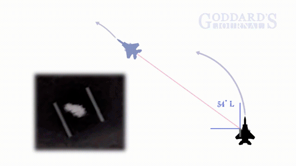
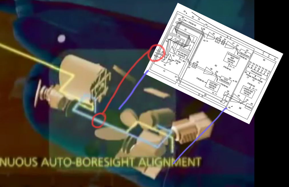
I believe the portion of the system you show is the rearward portion...


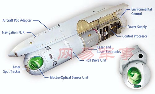
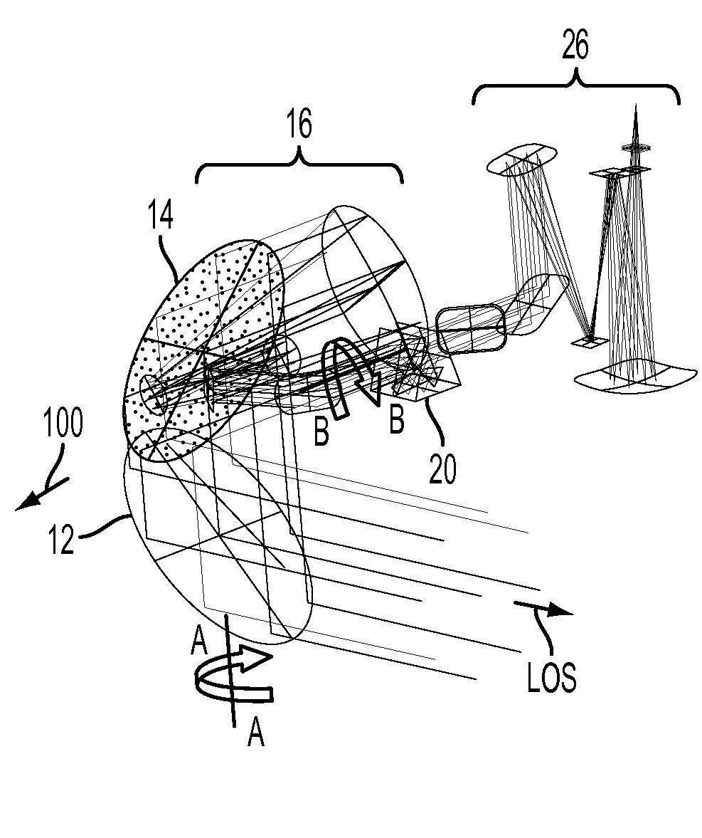
A Raytheon patent you linked to, which seems to be for the forward camera in the ATFLIR, says 'gimbal lock' can occur when LOS = 0˚ (which is also "roll axis BB"), and to avoid that gimbal lock, rotational adjustments are made...

[0035] ... The situation where the LOS is precisely parallel to roll axis BB and thus causing the roll axis BB to not steer the LOS is called a “gimbal singularity” or “gimbal lock.” A control gain of roll axis BB is proportional to 1/sin α. Hence, the gain of roll axis BB can go to infinity when α is equal to 0, i.e., when the LOS is precisely parallel to roll axis BB. From the standpoint of an automated control system 90 (shown in FIG. 1) for controlling the orientation of c-mirror 12, i.e., controlling the rotation around roll axis BB and rotation around axis AA, this gimbal singularity may be problematic because no amount of rotation around roll axis BB produces any desired effect of steering the LOS.

[0036] As a result, in certain applications, the gimbal singularity is to be avoided. However, in an embodiment, where the gimbal singularity cannot be avoided, for example because the gimbal singularity is within the desired field of regard (FOR), then it may be desirable to provide a third gimbal axis TT (shown in FIG. 1). In one embodiment, third gimbal axis TT is within the plane of c-mirror 12 and is perpendicular to rotation axis AA. In one embodiment, the third gimbal axis TT resides on rotation axis AA of c-mirror 12 in that a rotation of c-mirror 12 around axis AA produces a rotation of axis TT. The third gimbal axis TT can be of small angular travel (for example, less than or equal to 5 deg.). As a result, axis TT travels around roll axis BB and avoids the gimbal singularity.

[0037] For example, when an object being continuously tracked by moving c-mirror 12 in various directions by rotating around rotation axis AA and/or around roll axis BB and/or optional third axis TT using control system 90 is projected to go close to or through the gimbal singularity, and optional third gimbal axis TT is provided with a range of angles α, for example, ±3 deg, roll axis BB is no longer used for tracking the object within the ±3 deg. range that surrounds the gimbal singularity. Instead, rotation axis AA and third gimbal axis TT are used to continue to track the object within the ±3 deg. angular range. When, on the other hand, the object location exceeds, for example, the 3 deg. singularity, roll axis BB is used by control system 90 in the tracking motion. In this case, the third axis can be gradually returned to 0 deg. and no longer has involvement in the tracking motion. In other words, control system 90 controls the tracking by rotating c-mirror 12 around third gimbal axis TT when an object is located closely around the singularity (e.g., within the ±3 deg. range). Otherwise, when the object is outside the ±3 deg. range around the singularity, control system 90 controls the tracking by rotating roll axis BB and leaving the third axis TT fixed or returning third axis TT to 0 deg.​


If I'm reading that right, it says rotational adjustment in the optics are made as the LOS sweeps across 0˚.

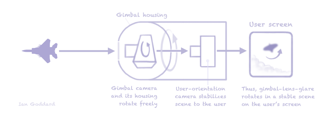
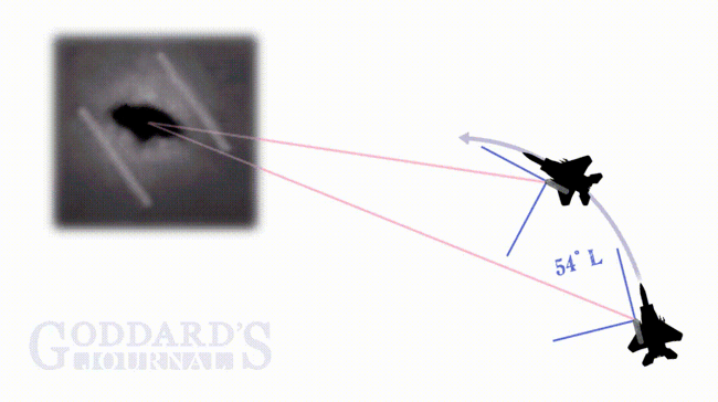
A homespun example of gimbal lock...

 
Last edited:
No, it's quite clear that 54 is the "wind screen" window, i.e. on the outside.

The gimbal housing has two separate windows one for the Laser Spot Tracker and the second for EO/IR.


But the figure shows 54 as one common window for both laser and IR together, just like the boresight aligned path that patent involves, and the Raytheon animation shows the aligned path to feed into the rear 'camera'.

Patent 20120292482A1 in contrast shows the LOS to targets...


It also describes the LOS to targets in the text I quoted above. So surely this is on the forward camera that looks directly at targets. "Roll axis BB" is seen above, and the patent says when LOS is aligned with BB, adjustments are made to prevent gimbal lock. So this looks like a fit to what we've deduced from the gimbal video.
 
Last edited:
The gimbal housing has two separate windows one for the Laser Spot Tracker and the second for EO/IR.
But the figure shows 54 as one common window for both laser and IR together, just like the boresight aligned path that patent is about, and the Raytheon animation shows the aligned path to feed into the rear 'camera'.

The IR, TV, and Laser Target Designator/Rangefinder (LTD/R) use the common big window. The Laser Spot Tracker (LST) is a separate sensor that looks out of the small window and tracks laser spots that are projected by other aircraft or forward air controllers to mark a target.
 
The IR, TV, and Laser Target Designator/Rangefinder (LTD/R) use the common big window. The Laser Spot Tracker (LST) is a separate sensor that looks out of the small window and tracks laser spots that are projected by other aircraft or forward air controllers to mark a target.
Citation? The animation never shows the laser (blue line) going out the forward IR sensor....


You are saying the blue line should shoot out the path along which the yellow line enters the front, but it does not. The only place we see the blue and yellow lines overlap is feeding into the rear set of components, matching window 54 in Patent 6288381B1.
 
Citation? The animation never shows the laser (blue line) going out the forward IR sensor....
You are saying the blue line should shoot out the path along which the yellow line enters the front, but it does not. The only place we see the blue and yellow lines overlap is feeding into the rear set of components, matching window 54 in Patent 6288381B1.

Like Mick said, the patent diagram shows the outer wind screen 53 that has the common window 54 in it, so yes the laser shoots out of the same window.
 
Okay Agent, sorry, I think you and Mick are right and the animation just does not show the full laser path. What I was saying was based entirely on Raytheon's animation above. And that's where it ends, never showing the laser's path exit the forward sensor. However, the written description seems to match your description:

The targeting FLIR, EO sensor, laser rangefinder and target designator share a common optical path with continuous automatic boresight alignment. This design approach minimizes boresight errors between the sensors and laser lines of sight (LOS) and is key to the ATFLIR's performance improvement over previous systems. This design approach enabled three pods to be replaced by one and it also significantly streamlines operations because it eliminates the requirement to co-boresight multiple pods on the aircraft.

The Electro-Optical Sensor Unit (EOSU) contains the third-generation staring medium wavelength targeting FUR and the EO camera. The focal plane in the targeting FLIR is 640 x 480 pixels InSb operating over the spectral band of 3.7 to 5.0 nm. The pilot may select the field of view during operation. The EO camera operates in the visible spectrum. The EOSU also contains all of the optical elements that form the common optical path and the Laser Spot Tracker.

[...]

ATFLIR can also track targets designated by ground forces or another aircraft using the Laser Spot Tracker (LST). The LST is integrated into the EOSU. It senses the laser spots designated by ground forces or another aircraft and provides information to the ATFLIR tracker and control so that the common optical path LOS can be pointed automatically at the designated spot.

From: Raytheon advanced forward looking infrared (ATFLIR) pod

So it sounds like the boresight alignment should cover about the entire optical path, unlike the animation shows.
 
Last edited:
I believe Tom nailed a fact central to the rotational cause on page one of this thread, there's a gimbal-lock problem with these gimbal-camera systems when they point straight ahead, ie, when LOS = 0˚:
There is however, something worth noting with regards to it's configuration: All gimbals of this design suffer from a problem known as "keyhole" ( https://en.wikipedia.org/wiki/Keyhole_problem ), or sometimes referred to as "gimbal lock" ( see the 2 dimensional description of it here: https://en.wikipedia.org/wiki/Gimbal_lock ). For gimbals such as the Wescam MX series and most FLIR, keyhole occurs at a point directly beneath the aircraft -- pilots and sensor operators coordinate to avoid getting into this geometry. (Our company produces a free "pilot display" app for iOS that assists in this effort: https://churchillnavigation.com/pilot-display/ ) The AN/ASQ-228 is essentially a similar design of gimbal, but turned 90 degrees -- meaning they have a keyhole problem when looking directly ahead. I would guess the "stutter" in the video is related to this issue -- the gimbal not having enough control authority to follow the rate commands from the AVT (automatic video tracker). The issue would be much worse if they were looking directly ahead, rather than 2 degrees down. (The inner stages usually provide +/- a few degrees of stabilization, which might account for the stutter not being seen at exactly 0 degrees relative azimuth)

And that is exactly what Raytheon's Patent 20120292482A1 describes, the risk of gimbal lock as LOS = 0˚. This is surely near the answer for the curious rotation as LOS sweeps across 0˚...

 
Citation? The animation never shows the laser (blue line) going out the forward IR sensor....


You are saying the blue line should shoot out the path along which the yellow line enters the front, but it does not. The only place we see the blue and yellow lines overlap is feeding into the rear set of components, matching window 54 in Patent 6288381B1.

I don't think the cartoon is very useful, but the blue line is probably meant to represent the low power laser reference beams from 21,31,41 on their way to photo detector just after 19.
 
A very-good question posted to my video:

Martin Willis Live Shows 1 hour ago
Wouldn't they know if the craft filmed had a transponder or not?​

Of course we only get a 30-second glimpse into the gimbal-video cockpit. So how quickly one might expect to receive transponder data is a relevant question. Is transponder data expected to appear along with any target immediately (I suspect not), or is it given only upon interrogation?

Another point is, given we have no location data, we can't rule out that the other aircraft or the alleged "fleet of them" are from a foreign military. These pilots might, for example, be flying near China or Russia.

Transponder data, if present, is only useful if you are looking in the right place. So you can only tell if a craft you are looking at has a transponder if you check all the way along the line of sight. If you stop at ten miles then you'd miss something that's 20 miles away.
 
A very-good question posted to my video:

Martin Willis Live Shows 1 hour ago
Wouldn't they know if the craft filmed had a transponder or not?​

Of course we only get a 30-second glimpse into the gimbal-video cockpit. So how quickly one might expect to receive transponder data is a relevant question. Is transponder data expected to appear along with any target immediately (I suspect not), or is it given only upon interrogation?

Another point is, given we have no location data, we can't rule out that the other aircraft or the alleged "fleet of them" are from a foreign military. These pilots might, for example, be flying near China or Russia.

In peacetime, they should try the transponder and IFF and establishing radio contact before deciding that the aircraft is not friendly.
 
...These pilots might, for example, be flying near China or Russia...

I agree. These "pilots" might also, for example, be voice actors.

...Another point is, given we have no location data, we can't rule out that the other aircraft or the alleged "fleet of them" are from a foreign military...

Excellent point! What data was used to rule out that the audio recording of the alleged "pilots" isn't fake?
 
Back
Top