If we assume both the aircraft and the UAP are moving in straigth lines at constant speed, the theoretical heading of the camera tracking the UAP would be of the form :
heading over time:
\[
tan(\theta(t))=\frac{y_{UAP}(t)-y_{AIRCRAFT}(t)}{x_{UAP}(t)-x_{AIRCRAFT}(t)}
\newline\newline\newline
\theta(t)=atan(\frac{y_{0_{UAP}}-y_{0_{AIRCRAFT}}+(v_{y_{UAP}}-v_{y_{AIRCRAFT}})*t}{x_{0_{UAp}}-x_{0_{AIRCRAFT}}+(v_{x_{UAP}}-v_{x_{AIRCRAFT}})*t})
\newline\newline\newline
\theta(t)=atan(\frac{A+B*t}{C+D*t})
\]
with A,B,C and D constants.
I used gradient descent to estimate A,B,C and D from Mick's measured headings (using data from frames between 2500 and 10000) :
This values multiplied by the same non zero factor would also work.
With A,B,C and D you can simulate the heading over time :
There is a good match between the measured and simulated data, the constant speed hypothesis seems to be close to the reality.
A,B,C and D can be used to reconstruct the trajectory of the UAP in the aircraft frame of reference.
UAP trajectory angle = atan(b/d) = 5 degrees
I animated the scene in blender. The camera rotation is from Mick's heading data, the UAP position is calculated from A,B,C and D.
(animation sped up x100)
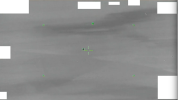
Left side : View from the camera
Right side : Top view, the black triangle is the camera, the sphere is the UAP


 . However, I now think the light areas arent necessarily water - I think it is low lying mist, maybe suggesting that the video was recorded early morning.