Gimbal distance and Speed Range Estimates using Lines of Bearing and/or DCS

So he spends his first ten minutes justifying his original assumption of 3 deg/sec, and how it's so important for safety around airports etc. But then a few minutes later he's revised his estimate to 2.27 deg/sec. (That's an extra 38sec to complete a safety-critical "standard turn".) The "standard rate of turn" assumption has thus been completely discarded -- as well it should, for a plane flying way out over the ocean in military-exclusive airspace and very little other traffic.

His new rate of turn (which doubles his estimated range from ~4nm to ~8nm) is driven by a true airpseed of 400kt vs Mick's 350kt. His mistake is easy to spot, at 18m20s. He's kept the calculator's default air temp at 20C (68F), while standard atmospheric models give air temp at 25kft to be -34C (-30F). This leads him to inflate the true airspeed and throw off his calculations.
 
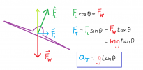
Quick free-body diagram illustrating Lehto's main mistake.

The lateral acceleration (and thus the turn rate) is independent of weight because the vertical component of the lift vector cancels the weight during level flight.
 

Attachments

  • lift.png
    lift.png
    27 KB · Views: 324
He added a comment:

Source: https://www.youtube.com/watch?v=1DTYqMqc3cU&lc=Ugx54BLXwr9kfECZ2Td4AaABAg.9OQJl3f4JyQ9OQU_VeGOSk


Chris Lehto
16 minutes ago

Yes, I was incorrect on the reason for Mick's discrepancy. A heavier aircraft will go around the larger circle faster but have the same rate. Sigh...instruments. But his results are still wrong and don't match the simulator. Thankfully we have simulators and rules of thumb, I should have just let Mick come up with the answer.
Content from External Source
"A heavier aircraft will go around the larger circle faster but have the same rate." sounds like nonsense. We know the speed of the plane, it does not change significantly from 241 knots CAS (240-242). If you have a constant rate of turn and constant speed, then the radius is going to be constant, regardless of mass.

I think Lehto's argument here is that the higher g forces indicate that the plane is turning on a narrower radius than what you would get for a coordinated turn at 30 degrees bank angle. That's valid and needs to be taken into account and it cannot be determined from just looking at the angle of the flight path indicator. You need to take the g forces into account as well to actually determine the (varying) turn radius.

But is there evidence that it's not in a coordinated turn? It seems to be in speed and altitude-hold autopilot, as it maintains a constant speed and altitude. Chris tried to do this in the simulator, but could not get it to work.
 
Finally someone decided to try and simulate this on DCS! Love it. We need someone to download it here too. I don't own a PC unfortunately.

I'm not sure how much the loadout would affect the test. But I doubt they were flying with a full load out (all missiles tanks etc.). I would set up the aircraft with a more average loadout.

In any case he can't be off by much at this point.

If we are assuming a static object we have 3 pretty close points that could realistically indicate a static position for the 3 observations. I think that is the minimum distance.

If the object is moving then Chris shows the maximum realistic distance possible.

Those are still pretty close ranges. Even if we double them up we are at a very close intercept range for an F-18. It should be clearly visible on ATFLIR/Radar etc.
 
But is there evidence that it's not in a coordinated turn? It seems to be in speed and altitude-hold autopilot, as it maintains a constant speed and altitude. Chris tried to do this in the simulator, but could not get it to work.
I did a bit of research on the autopilot modes and it seems there's attitude hold, two altitude hold modes, a course selection mode and a coupled mode that allows you to navigate to waypoints etc. There's also an auto-throttle button that holds your TAS. I would say the varying bank angle indicates that attitude mode is not engaged and all other navigational modes would (probably) use a fixed bank angle for coordinated turns.

In this sense, there is no indication or auto-pilot limitation that requires a coordinated turn. Indicated airspeed seems to increase by almost 2 percent rather than oscillate, but I'm not sure how precise the auto-throttle would be for that to be any indicator of auto-throttle on vs. auto-throttle off.

If I was in that plane (rather than in front of my cheapo flight sticks in front of the computer screen :D) I would probably also just engage altitude hold and auto-throttle while handling my turn as I see fit to follow the target.
 
Important addition for my post above: I just found out thanks to Chuck's Guide that any altitude hold mode in the plane will actually require you to either fly straight and level or have heading- or attitude-hold mode engaged prior to this enabling altitude-hold mode as well.

So they were at most using auto-throttle or they could have also used the HSEL heading select mode, set a course and used the little bit of freedom it gives you to modify the roll angle a bit. But since the roll angle varyies form 25 to 35 degrees, I'm betting they flew manually (perhaps with auto-throttle).
 
Looking at this with the Geogebra schematic, the distance strongly depends on the points that are used to construct the intersection. A strong asumption is that the bank angle is constant, at 30°, but it is clearly changing from points 1 to 4. Here are screenshots of the Gimbal video, with a focus on the bank angle, at the 4 points taken every 10sec, with a protactor overlaid (cool online too I found) to measure the bank angle.

Point 1 (53° camera angle) :
Bank Angle 53.JPG


The bank angle is about 26° -> 1.3-1.4 Rate of Turn based on the Bank Angle vs RoT graph you use

Point 2 (38° camera angle) :
Bank Angle 38.JPG

The angle is about 31° -> ~1.6-1.7 Rate of Turn

Point 3 (21° camera angle) :
Bank Angle 21.JPG

The angle is about 36° -> ~2.3-2.4 Rate of Turn

Point 4 (1° camera angle) :
this point is kinda dismissed but it's an interesting one, the plane is now basically pointing towards the target

Bank Angle 1.JPG

The bank angle is still 36°, so here we have a constant RoT for 10 sec (2.3°/sec).

I've added point #4 in Mick's Geogebra (see below), with this RoT of 2.3°/sec, the intersection between Pt3 and Pt4 gives a distance of about 5.4 Nm. Using Intersection23 with a RoT of 2°/sec (average between Pt2 and 3) gives a distance of~10Nm. For sure, the results depends a lot on which points/intersection is analyzed. I would argue Pt3 and Pt4 may provide a better estimate because the bank angle, hence rate of turn, is constant between them (since the fighter speed stays the same). I'm not very good at geometry so I do not pretend being right here, and I appreciate any insights on this.

Gimbal Lehto.png
 
Last edited:
Hey all, longtime lurker here. Unless I am missing something, Chris is completely wrong when he claims the weight of the plane is relevant to calculating the turn rate for a plane in a level turn.

Let n = the g loading factor
L = lift
Lv = vertical component of lift
W = weight
ϕ = bank angle

n = L/W by definition

W = Lv for a plane in a level turn

Lv = L cos(ϕ)

Therefore n = 1/cos(ϕ)

Any plane in a level turn at bank angle ϕ will have the same load factor, regardless of speed and weight.
 
Very interesting simulator he used as well. Does anyone here use that software ? Particularly interested that you could in theory plot the gimbal encounter and observe how the atflir pod follows. Whether it’s in constant motion or not. May not be definitive or 1:1 accurate but it seems pretty detailed.
 
It's DCS it's 60 UK pounds for the f/18 pack. I'm fairly close to picking it up at this point I've read enough ATFLIR manuals I can probably use it from memory. However it's only recently the ATFLIR was added though and not all the features we see in the videos are in, in fact it's quite telling that the hardest parts for them to simulate are some of the things we see in the video. I doubt they will actually simulate stuff like IR glare and physical lens changes causing track loss. I think they just added auto track but it's just faked they didn't actually simulate the IR and contrast tracking etc
 
It's DCS it's 60 UK pounds for the f/18 pack. I'm fairly close to picking it up at this point I've read enough ATFLIR manuals I can probably use it from memory. However it's only recently the ATFLIR was added though and not all the features we see in the videos are in, in fact it's quite telling that the hardest parts for them to simulate are some of the things we see in the video. I doubt they will actually simulate stuff like IR glare and physical lens changes causing track loss. I think they just added auto track but it's just faked they didn't actually simulate the IR and contrast tracking etc
Interesting. The most fascinating bit of his video was watching the gimbal pods motion. Do you think that it would simulate its tracking capability by actually moving on its axis as in reality ? That would be intriguing.
 
Hey guys, I had this feeling that something is wrong with the object being distant, and making more detailed analyses of the geometry confirms that. This is a fun problem to work on ! I started from Mick's Geogebra, but instead of having a constant Rate of Turn, I make it change along the course of the flight (see my post above that shows how the bank angle, hence rate of turn, changes from Pt 1 to Pt4). So there are different circles for Pt 1, 2 3 and 4 (3 and 4 are on the same circle because the bank angle does not change between them). Rather than fixing the different angles between Pt1/2/3/4 and Gimbal, I try to find a trajectory for Gimbal that would match the trajectory of the plane (along Pt1/2/3/4), and the corresponding IR camera angles (53°, 38°. 21°, 1°). I use a True Air Speed of 360 Knts (like Mick).

By doing that, it is clear that the object cannot be very distant. Or it would move at supersonic speed, which is not at all in line with the plane/glare theory. The only way I find a trajectory that matches the plane position, and camera angle, is for fairly close distance of ~5Nm. Here is an example, this is a GIF that shows a potential trajectory with more or less constant distances between the fighter and Gimbal (4-5 Nm) :

Gimbal Close.gif

Look at the angles 1, 2 , 3 and 4 between Pt1/2/3/4 and Gimbal, I make them match the camera values (53/38/21/1) from one point to the next. The distance given in red is the corresponding distance from the new plane position. It stays between 4 and 5 Nm. Playing with possible trajectories, that are not many that fit these camera angles, and especially with larger distances from the fighter.

The more Gimbal is moved away from the fighter, the more impossible the angles are to match, or the object would have to cover a super large distance, greater than the plane (i.e. move at supersonic speed). Here is an example with a distance of 50Nm, for PT1 and PT4 (the other points/angle don't even make sense).

Gimbal Far.gif

You can see how large would the distance be compared to the distance covered by the fighter (that goes at 0.6 Mach). And this is for a distance of 50Nm only, it is even less sustainable for greater distances.

Sorry if this is obscure but I hope it will make sense to those who have played with this schematic, especially Mick. I may be wrong, but if I'm not it is clear that Gimbal cannot be very far from the fighter, it simply does not align with the camera measurements. I'm not trying to prove one side or the other, I just find it a fun puzzle to solve, and hopefully this brings something interesting on the table. If I'm wrong I'd be happy to hear where this can be fixed.

I'd like to share the GeoGebra project so you can all play with the Gimbal position, but GeoGebra does not send me the confirmation email for registration, so I'm stuck with showing GIFs for now. But I can share the GeoGebra file (gpp) if somebody is interested in this model, I was able to save it.
 
Last edited:
Sorry if this is obscure but I hope it will make sense to those who have played with this schematic, especially Mick. I may be wrong, but if I'm not it is clear that Gimbal cannot be very far from the fighter, it simply does not align with the camera measurements. I'm not trying to prove one side or the other, I just find it a fun puzzle to solve, and hopefully this brings something interesting on the table. If I'm wrong I'd be happy to hear where this can be fixed.
I think really the next step would be to do a frame-by-frame analysis in code to get a continuously varying curve, rather than a series of arcs. A fun challenge I might get into next week - although I suspect others might beat me to it.

Ultimately it would be good to find a way of using a simulator. DCS has a Lua scripting engine which might work, but I can't quickly find if it exposes the plane's controls in a simple way.
Does anyone have a spreadsheet with all the data? I tried looking in past threads and couldn't find it.
 
If I am not completely wrong and based on 20 years of sim flying, I think what Lehto is talking about is that you don't just turn an airplane by banking. You also need to apply some pressure on the stick, thereby increasing the g load, to make a turn and remain level, otherwise you will slip. This in turn requires you to add some rudder to counteract your slip. You can turn harder at the same bank angle by applying even more force on the stick, but your turn will be even more uncoordinated, your altitude would increase AND you would need to counteract that with your rudder AND you would increase the load on the plane.

Looking at the chart, the lines for 30 deg bank angle show you the corresponding g load when doing a coordinated turn, i.e., when the rudder applied exactly counterbalances the additionally required angle of attack at 30 degrees bank to facilitate a standard rate turn. It doesn't mean that every turn at 30 deg bank will automaticall be a standard rate or coordinated turn at the given TAS. You can just bank and make your HUD indicate a 30 degree angle but by applying enough rudder and force on the stick, not even turn at all.

I think Lehto's argument here is that the higher g forces indicate that the plane is turning on a narrower radius than what you would get for a coordinated turn at 30 degrees bank angle. That's valid and needs to be taken into account and it cannot be determined from just looking at the angle of the flight path indicator. You need to take the g forces into account as well to actually determine the (varying) turn radius.
Indeed there's an assumption that the lift vector points upwards normal to the plane of the wings (or whatever corresponding symmetry plane when there's a dihedral, etc. -- you know what I mean). Note that even Lehto assumed that this is the case, and it's an assumption that always goes together with the phrase "standard rate turn". In uncoordinated flight the results can be different. However, uncoordinated flight is inefficient and there'd be no tactical reason to use it. I could see a fighter pilot using uncoordinated inputs in a dogfight to trade energy for turn radius/nose position, but what we're seeing looks like a fairly standard intercept with the F-18 getting in (again what looks like) an advantageous position. So there'd be no reason to perform a maneuver as crass as a slip/skid.

As an aside, these aircraft have pretty small adverse yaw tendencies, and require very little rudder input from the pilots for proper coordination. I first heard this from CW Lemoine (sorry, I don't remember the exact video), but it can be easily verified in simulators. Whether this is a result of aerodynamics or the flight control system automatically applying the proper inputs I don't know, but the end result is that the assumption of coordinated flight is a pretty good default assumption here. Again, Lehto himself assumed this (around 13:40 in the De^4-bunking video), so he couldn't possibly have meant that the pilots were trying to turn faster than ordinary coordinated flight allows.
 
Of course the distance is key here. If it's close then it's clearly not a plane, or anything with a clear propulsion signature.

Here is my Geogebra model (adapted from Mick) that allows to play with the Gimbal position, and figure the different distance d1/d2/d3/d4 from Point 1/2/3/4 :
https://www.geogebra.org/classic/jjxxmdxs

You can move the Gimbal object, and follow the values of d1/d2/d3/d4 on the left of the screen. Units are in Nautical Miles (the selected airplane speed is 360 Knots, i.e. 360 Nm/h).

It's very easy to see that a long distance for Gimbal just does not match the plane trajectory and IR camera angles. Or Gimbal would have to cover a very large distance, hence moving at supersonic speed. This is quite simple geometry really, I let you guys figure it by yourself. At this point I really think this is a legit footage, and not any camera artifact.
 
Again, Lehto himself assumed this (around 13:40 in the De^4-bunking video), so he couldn't possibly have meant that the pilots were trying to turn faster than ordinary coordinated flight allows.
First off, thanks for your valuable input. Also, yes, I don't think Letho is arguing very consistently in these videos, so it's all a bit of a mess.

Concerning coordinated vs. uncoordinated turns, I did read a comment by an F/A-18 pilot on reddit at some point where he mentioned that some of his colleagues like to use lots of rudder and an uncoordinated turn when using the targeting pod. But I can't find it right now. In any case, this is probably something that the pilots themselves will have to answer.

The only thing I wanted to point out is that given the (limited) info in the video, it is not correct to assume that we have all the variables covered by just looking at/tracking the angle and the chart. I was totally shocked last night that I did not realize this before and only realized it thanks to Letho's video and your initial comment.

I also agree with the others that using DCS with a more stable, scripted approach would probably be the best thing to do. I do have DCS and the F/A-18 module, but I don't have it installed (it's huge ... like 200 GB if you have several of the modules) and I don't really have time for this stuff right now (kids, work). Another idea would be to track the cloud and cloud parallax by employing some kind of cloud-size model. That could also give us an additional scalable data point for the true angles.
 
I think post #126 makes it quite clear that Chris was wrong about weight affecting load factor and the resulting turn rate, and he's admitted that on Twitter:


Source: https://twitter.com/chrisotis78/status/1403123732193947649


What should be done now is for someone with the DCS F-18 module to try to recreate the flight path of the F-18 in the video with the autopilot engaged in barometric altitude hold mode. It's quite possible that it would produce different results to what Chris got. Here's a video that shows how to engage the autopilot:


Source: https://www.youtube.com/watch?v=tTBr-nTedvE

And here's how to engage the auto throttle:


Source: https://www.youtube.com/watch?v=1mMlg2Ite_g


Even though the weight of the aircraft shouldn't affect the turn rate in theory, these tests should be done with different fuel loads to see how the weight affects the aircraft performance in the simulator. Chris initially claimed that the weight of the aircraft was important, but he didn't specify what kind of fuel load he started with in DCS.

EDIT: included a video on how to use the auto throttle.
 
Last edited:
Ok guys, I had an error in my schematic (previous page). Pt3 and Pt4 were wrongly positioned, underestimating the total turn of the fighter. The total angle of turn of the fighter from Pt1 to Pt4 is ~55°, close to the angle of turn of the camera (52)°. So I think what's happening here is the fighter is closing on Gimbal, until it is right behind it. The new schematic allows for more potential trajectories at greater distances, but I find they are still unlikely once Gimbal is beyond 10-15 Nm. But beware that small changes in angle of turn affect the end results, so there are uncertainties here. The Rate of Turns can now be adjusted in a very easy way, all the other parameters adjust to it. My main goal when I find time is to get a range of uncertainties (or level of confidence) for close to very distant Gimbal-fighter distances
https://www.geogebra.org/classic/vb5qg3vf
 
Last edited:
Hello all, first post! I have attached my stab at the GeoGebra modeling. I considered all the different bank angles from the original video and modeled the turn radius and rate based on the info available (airspeed, bank angle). Unfortunately, we don't have any data on if these are coordinated turns or not, which could significantly impact the accuracy of the model as it would make it impossible to extract an accurate turn rate. If the turn is coordinated and level, all you need are bank angle and speed to deduce the turn rate. You can also extract turn radius from this information, but it will only be accurate if there is no wind. I think there was 100 kts of wind in this scenario, which would have a big effect on turn radius. I'm not sure how lack of wind modeling will influence our results here, but it seems like turn rate has a bigger impact than radius on the results.

To explain the model:
There is a corresponding line of bearing drawn at each point where the bank angle changes. The colors of the lines are in ROYGBV order from point 1 to point 6 respectively. As you can see the first 4 lines tend to converge and then the last two, blue and magenta, break from the pattern of convergence. The larger circle is drawn at 16NM and seems to be about where the lines start to diverge again.

My first theory is that the object is flying away from the F-18 along the first 4 lines of bearing, somewhere between 12-16NM. The last two bearings blue/magenta seem to be in opposition to this theory, perhaps due to some uncoordinated turns and/or some inaccuracies involved with the pod rotation, as they are both within the sensor azimuth range where it starts to rotate. Additionally, the rate of change of the azimuth of the pod is very rapid towards the end of the video, which made it challenging to know what angle/time to insert into my calculations. My main sticking point with this theory is that with the amount of aspect change to the object, I would think you would see more change in the actual shape of the object, although that could simply be masked by the "glare".Untitled.png

My second theory assumes that there are no distortions from uncoordinated turns or any other anomalies with the ATFLIR. If that is true, the only thing that made sense to me is a turning rejoin being performed with another object that is relatively close (roughly depicted by the dashed orange line). The main problem that sticks out to me about this theory is that the size of the object doesn't appear to change very much, which you would expect based on the geometry here.

Untitled2.png
A frustrating analysis as it's not definitive one way or another. I've never used GeoGebra before so it's possible I made a mistake, although I checked it over multiple times. Perhaps Mick can apply his skills to generating a more detailed model using the extracted bank information.

Finally, I can't think of a single aerodynamic concept that Chris has portrayed correctly in his videos, so if anyone is confused on these topics, please feel free to ask (I'm a commercially/instrument rated pilot with over 3k hours).

Hey it looks like we are many to play with Geogebra now :D Could you share your model ?
Here is mine : https://www.geogebra.org/classic/vb5qg3vf
If you have a chance could you check if that is consistent with what you find ? I also find that a distance between 5-15Nm is the most likely

And I have a question : do you confirm that the rate of turn is only proportional to the bank angle, and that other parameters (except for speed of course) do not influence it (type of plane, pressure, atmospheric conditions, ...) ?
 
Last edited:
I used the autopilot and ATC in DCS at 30 degrees bank, 25,000ft and Mach .58 and could only ever get a turn rate of 1.75 degrees per second Even after jettisoning 3 tanks of fuel (the pictures show it at 16,000 and 10,500 lbs of fuel).
withFuel.jpgwithoutFuel.jpg
The Tacview files shows that the turn diameter is 6.4nmi and doesn't change with the weight, which makes sense to me as there is no real reason why it would. It also agrees with the turn capability graphs and the stuff Mick did with GeoGebra.
tacview.jpg
I've watched Chris Lehto's video a few times and I'm not convinced with 2.27 degrees per second, the bank angle changes quite a bit and he's pulling anywhere between 1.0 and 1.3 g's at a time which on the graph is about a 40 degree change in roll, significant even if what he says about the weight changing the numbers is correct. I don't want to say that an actual fighter pilot isn't flying it accurately but it can be very hard to keep it at 30 degrees with a keyboard as well as maintaining speed and altitude without using the autopilot on a simulator that he just got.
 
Great job! Although I expected there to be no difference between the heavy and light fuel load runs I wasn't sure whether it would be properly modeled in DCS, and your results have now clearly shown that it is. Looking at the two runs I can see that the one with the higher fuel load has a slightly higher g-load (1.2 vs 1.1). That appears to be due to the plane climbing slightly, and thus pulling a bit harder, in the run with the higher fuel load (starts at 25020 ft and ends at 25030 ft). In the run with the lower fuel load it's descending slightly (starts at 25040 ft and ends at 25030 ft). There's also the fact that the g-value is only displayed with one decimal in the HUD. The chart Mick used to figure out the turn rate gives a load factor equal to 1.15 g for a bank of 30 degrees, which would make the value displayed in the HUD very sensitive to small changes in the load factor due to the rounding.
 
Last edited:
I used the autopilot and ATC in DCS at 30 degrees bank, 25,000ft and Mach .58 and could only ever get a turn rate of 1.75 degrees per second Even after jettisoning 3 tanks of fuel (the pictures show it at 16,000 and 10,500 lbs of fuel).
withFuel.jpgwithoutFuel.jpg
The Tacview files shows that the turn diameter is 6.4nmi and doesn't change with the weight, which makes sense to me as there is no real reason why it would. It also agrees with the turn capability graphs and the stuff Mick did with GeoGebra.
tacview.jpg
I've watched Chris Lehto's video a few times and I'm not convinced with 2.27 degrees per second, the bank angle changes quite a bit and he's pulling anywhere between 1.0 and 1.3 g's at a time which on the graph is about a 40 degree change in roll, significant even if what he says about the weight changing the numbers is correct. I don't want to say that an actual fighter pilot isn't flying it accurately but it can be very hard to keep it at 30 degrees with a keyboard as well as maintaining speed and altitude without using the autopilot on a simulator that he just got.
Very interesting, have you tried with variable bank angle matching what is seen on the Gimbal video?
 
I used the autopilot and ATC in DCS at 30 degrees bank, 25,000ft and Mach .58 and could only ever get a turn rate of 1.75 degrees per second Even after jettisoning 3 tanks of fuel (the pictures show it at 16,000 and 10,500 lbs of fuel).
withFuel.jpgwithoutFuel.jpg
The Tacview files shows that the turn diameter is 6.4nmi and doesn't change with the weight, which makes sense to me as there is no real reason why it would. It also agrees with the turn capability graphs and the stuff Mick did with GeoGebra.
tacview.jpg
I've watched Chris Lehto's video a few times and I'm not convinced with 2.27 degrees per second, the bank angle changes quite a bit and he's pulling anywhere between 1.0 and 1.3 g's at a time which on the graph is about a 40 degree change in roll, significant even if what he says about the weight changing the numbers is correct. I don't want to say that an actual fighter pilot isn't flying it accurately but it can be very hard to keep it at 30 degrees with a keyboard as well as maintaining speed and altitude without using the autopilot on a simulator that he just got.
Yep, his demonstrations and descriptions of how an airplane turns and the forces acting upon it are out to lunch. Quite frankly, I'm shocked at his poor understanding of this stuff for a pilot of his qualifications. His DCS simulation was hand flown so the bank angle is changing constantly and is therefore invalid. A plane in level flight making a coordinated turn at a given bank angle will experience the same load factor, aka G's, regardless of the weight. If the G forces in a level turn increased based on weight, you would be crushed into your seat in a fully loaded 747. The actual variable between the heavy and the light aircraft will be the THRUST required to maintain the turn (keeping bank angle and airspeed constant). A heavier aircraft requires more lift to offset the weight. Generating more lift creates more drag, which is offset by thrust. This is why a Cessna can fly with a single prop and a 747 requires four jet engines, the heavier aircraft requires more THRUST. If you repeat your DCS simulation, pay attention to the engine parameters when executing the same turn at the same airspeed, the heavier jet should require more thrust to maintain the same airspeed in the turn.

The rate and radius of a level coordinated turn are not calculated using aircraft weight. The only inputs that matter are the bank angle and the True Airspeed. The one caveat to this is that wind will influence the turn radius, but not the rate. You can see the impact of wind in DCS by performing the turn without wind and then inserting 100 knots and repeating the same turn.

Online turn calculator (the outputs of this model assume no wind and level coordinated turn)

This link has a nice chart that illustrates the G-loading at various bank angles for a LEVEL TURN.

I believe the concept he may be trying to express would be covered by something like this diagram. The sliders depicted at the top allow modifications of aircraft weight, which would influence the results. However, this has no relevance in this discussion since the aircraft in question is in LEVEL FLIGHT.

The one caveat to all this modeling we are doing is that if these are not coordinated turns then (to my knowledge) we have no way of accurately extracting the turn rate. All the calculations for turn rate based on bank angle and airspeed assume a level coordinated turn. A coordinated turn is when the rudder pedals align the nose appropriately with the turn. I'm not sure how the F-18 flight controls work exactly, but as I understand they are fly by wire, so it probably automatically coordinates, unless the pilot manually steps on the rudder. I have read that some F-18 pilots like to use rudders when doing targeting pod work. My guess as to why they would do this would be to slow the rate of turn as the pod comes across the nose to mitigate the rotation, so that could have a significant impact on the modeling results. You can simulate an uncoordinated turn in DCS by inputting rudder opposite to the direction of turn while maintaining the bank angle and altitude. You will notice that the rate of turn slows down.

Clear as mud?
 
Last edited:
Hey it looks like we are many to play with Geogebra now :D Could you share your model ?
Here is mine : https://www.geogebra.org/classic/vb5qg3vf
If you have a chance could you check if that is consistent with what you find ? I also find that a distance between 5-15Nm is the most likely

And I have a question : do you confirm that the rate of turn is only proportional to the bank angle, and that other parameters (except for speed of course) do not influence it (type of plane, pressure, atmospheric conditions, ...) ?
Yep forgot to include that. Here you go!
https://www.geogebra.org/calculator/nyzk7fbx

Also, to answer your question, yes rate of turn only depends on true airspeed and bank angle, assuming the turn is coordinated and level. I just made a detailed post about that which you can check out.
 
Last edited:
I'm sure someone has already pointed this out, but in the course of 34 seconds in the video the direction of the FLIR scope changes from 54 degrees L to 7 degrees R, a total change of 61 degrees and an average change of 1.794 degrees per second. Of course this does not simply equate to the rate of turn of the jet, but it looks like the pilot is deliberately turning the jet in order to get a frontal view of the object, and slightly overshooting in the process. But if this is the purpose it is slightly odd that the jet is still banking, and therefore turning, quite sharply at the end of the video. Wouldn't the pilot have wanted to level out as they approached the 'front-on' view, because otherwise they would have continued to overshoot? It would be nice to know what happened after the video ends. I can't remember if the 'eye-witnesses' say anything about this.
 
I am now convinced Gimbal cannot be at more than 25 Nautical miles, with the most likely distance being 7-8 Nm. The geometry is fairly easy because Gimbal and the fighter are at a same altitude, and the fighter goes at constant speed. There is not much uncertainty on the trajectory of the plane, and the bank angles seen on the video are a good indicator of the different rate of turns along the flight.

Based on my model (https://www.geogebra.org/classic/vb5qg3vf), we can estimate potential trajectories of Gimbal that would match the camera angles (53, 38, 21 and 1 degrees at Points 1, 2, 3 and 4). You just have to move Gimbal (red dot) from any position on the black dashed line (53deg angle at Pt1), to the blue line (38deg angle at Pt2), to the orange, to the pink. The corresponding distances from the fighter (d1/d2/d3/d4) are given interactively.

We easily see that at large distances, matching the lines of trajectory means that Gimbal has to go towards the right (to go from black to blue), then turn back to the left to catch up with the orange and pink lines. Regardless of how bizarre that trajectory would be, pretty quickly the distance to do so would be too great for a plane (more than supersonic speed). I show a segment that gives the distance covered by an object at 500 knots (800 km/h, max speed of a commercial plane) as a reference.

I think the most plausible trajectory is for distances between Gimbal and the fighter of 7-8 Nm.

I see that you are discussing the fact that the rates of turn could be smaller than what Chris Lehto, or the bank angles on the video, suggest. Note that the inconsistency in the trajectory at great distances become even larger with smaller rates of turn ! Here I used rates of turn that go from 1.5 to 2.3 (they can be adjusted in my model, so you can check by yourself).

Visual examples of what I'm saying :

Gimbal-fighter distance of ~50Nm :
Gimbal 50.JPG

How could a plane cover so much distance ? It would have to go at roughly mach 2 (500 knots is 0.8 Mach).

Gimbal-fighter distance of ~25Nm :

Capture 25.JPG


From there, it starts to be doable for a regular plane (but needs some weird turns in its trajectory)

Gimbal-fighter distance of ~7-8Nm :

Gimbal 7.JPG

At this range, the trajectories make more sense, and the speed of Gimbal would be close to the speed of the fighter (they cover about the same distance).

Flight simulations are fancy, but for this question of trajectory and distance from the fighter, I don't see what it could bring that simple geometry like this cannot. I'm not trying to defend one side here, but the maths are what they are, sorry. I may try to make a video to explain every steps of this calculation.
 
Very interesting, have you tried with variable bank angle matching what is seen on the Gimbal video?

Yeah, I just used the angles from
Source: https://www.youtube.com/watch?v=zTuRheAI1LE
and the time to try and get it roughly similar (DCS lets you slow down the in game time to make it more accurate). I managed an OK match to the video (not great though), I'd do the cool Matlab track to double check if I knew how.


This gives an average turn rate around 1.8, so still not up at Chris's 2.26.

Untitled-1.jpg
 
Yep, his demonstrations and descriptions of how an airplane turns and the forces acting upon it are out to lunch. Quite frankly, I'm shocked at his poor understanding of this stuff for a pilot of his qualifications. His DCS simulation was hand flown so the bank angle is changing constantly and is therefore invalid. A plane in level flight making a coordinated turn at a given bank angle will experience the same load factor, aka G's, regardless of the weight. If the G forces in a level turn increased based on weight, you would be crushed into your seat in a fully loaded 747. The actual variable between the heavy and the light aircraft will be the THRUST required to maintain the turn (keeping bank angle and airspeed constant). A heavier aircraft requires more lift to offset the weight. Generating more lift creates more drag, which is offset by thrust. This is why a Cessna can fly with a single prop and a 747 requires four jet engines, the heavier aircraft requires more THRUST. If you repeat your DCS simulation, pay attention to the engine parameters when executing the same turn at the same airspeed, the heavier jet should require more thrust to maintain the same airspeed in the turn.

The rate and radius of a level coordinated turn are not calculated using aircraft weight. The only inputs that matter are the bank angle and the True Airspeed. The one caveat to this is that wind will influence the turn radius, but not the rate. You can see the impact of wind in DCS by performing the turn without wind and then inserting 100 knots and repeating the same turn.

Online turn calculator (the outputs of this model assume no wind and level coordinated turn)

This link has a nice chart that illustrates the G-loading at various bank angles for a LEVEL TURN.

I believe the concept he may be trying to express would be covered by something like this diagram. The sliders depicted at the top allow modifications of aircraft weight, which would influence the results. However, this has no relevance in this discussion since the aircraft in question is in LEVEL FLIGHT.

The one caveat to all this modeling we are doing is that if these are not coordinated turns then (to my knowledge) we have no way of accurately extracting the turn rate. All the calculations for turn rate based on bank angle and airspeed assume a level coordinated turn. A coordinated turn is when the rudder pedals align the nose appropriately with the turn. I'm not sure how the F-18 flight controls work exactly, but as I understand they are fly by wire, so it probably automatically coordinates, unless the pilot manually steps on the rudder. I have read that some F-18 pilots like to use rudders when doing targeting pod work. My guess as to why they would do this would be to slow the rate of turn as the pod comes across the nose to mitigate the rotation, so that could have a significant impact on the modeling results. You can simulate an uncoordinated turn in DCS by inputting rudder opposite to the direction of turn while maintaining the bank angle and altitude. You will notice that the rate of turn slows down.

Clear as mud?

It's only just dawned on me that this is what Chris is doing wrong. He flies the plane in DCS to get a turn rate of 2.27 degrees, then goes back to the graph, sees that this gives a wrong result and justifies his result by saying:
Heavier jets are going to require more g to maintain the same altitude. (around 17.40)
Which is complete nonsense
g-force, is a measurement of the type of force per unit mass. (https://en.wikipedia.org/wiki/G-force)
It's true that the a heavier jet requires more lift and thrust to maintain altitude, but the whole point in g-force is that it is independent of mass.

At the same time he mentions that lighter jets are better for dogfights so you might be right that he is getting confused with the potential/kinetic energy stuff for BFM manoeuvres. As I understand it the reason a light aircraft will turn better in BFM is because it can afford to dump speed to tighten the turn as it can quickly build energy again with the better thrust-weight ratio, whereas a heavy aircraft would dump speed, perform the same tight turn and then be a sitting duck.
 
All this geogebra stuff is getting a little convoluted for me, so I wrote a python script to plot these trajectories. I'm attaching it as a txt

Here are the results:
los-no-wind.png
data-no-wind.png

If we're being honest, that doesn't make much sense for a steadily moving target at _any_ distance. One possibility I considered is that there might've been some wind shear between the target and the F-18. Here's with a wind shear vector of (-20, 40) knots:
los-44kt-sw.png
A little better but still not rocking my socks off or anything.

I wasn't very rigorous about adding the data. I eyeballed some values off the analysis in
Source: https://www.youtube.com/watch?v=zTuRheAI1LE
for the bank angles, and read a few gimbal azimuth values directly from the video. The values for all times are obtained from the few chosen values by interpolation (I tried linear and cubic, didn't seem to make much of a difference). Still, improving that data would probably improve the analysis.
 

Attachments

  • gimbal.txt
    3.5 KB · Views: 217
All this geogebra stuff is getting a little convoluted for me, so I wrote a python script to plot these trajectories. I'm attaching it as a txt

Here are the results:
los-no-wind.png
data-no-wind.png

If we're being honest, that doesn't make much sense for a steadily moving target at _any_ distance. One possibility I considered is that there might've been some wind shear between the target and the F-18. Here's with a wind shear vector of (-20, 40) knots:
los-44kt-sw.png
A little better but still not rocking my socks off or anything.

I wasn't very rigorous about adding the data. I eyeballed some values off the analysis in
Source: https://www.youtube.com/watch?v=zTuRheAI1LE
for the bank angles, and read a few gimbal azimuth values directly from the video. The values for all times are obtained from the few chosen values by interpolation (I tried linear and cubic, didn't seem to make much of a difference). Still, improving that data would probably improve the analysis.

Thats kind of what I'm showing on my model as well. I didn't bother to model wind into mine but I think I should just be sure. Does your python model consider the effect wind would have on the turn Radii? We don't have the exact direction of the wind but they do mention the object is flying into the wind ("120 knots from the west"), so reasonable guesses could be made as to the angle.

The lines as shown kind of look like a turning rejoin to me. Something like the maneuver shown in this video, starting around 1:30
 
Yep forgot to include that. Here you go!
https://www.geogebra.org/calculator/nyzk7fbx

Also, to answer your question, yes rate of turn only depends on true airspeed and bank angle, assuming the turn is coordinated and level. I just made a detailed post about that which you can check out.

Thanks for sharing. We have very similar trajectories, and similar conclusion I think : the trajectory of Gimbal is very hard to reconcile with the camera angles if it was beyond 20-25 Nm from the fighter. To me the most plausible is for 7-8 Nm, or even closer. Of course keeping in mind the caveat you mention in one of your previous post, about the coordinated turn and how it may affect the estimate of turn of rate. Although while playing with different turns of rate in my model, I wasn't able to find a plausible trajectory at large distance
 
Last edited:
All this geogebra stuff is getting a little convoluted for me, so I wrote a python script to plot these trajectories. I'm attaching it as a txt

Here are the results:
los-no-wind.png
.

I think you got it without wind shear. Assuming the object is flying at a constant speed and direction, there is a point where the distance between the lines are the same about 13 km to 14 km away. Angle looks about right for the object flying away from the F-18. I don't know the time interval between the lines, so will let someone else figure the objects speed, but looks like it's pretty normal for a jet.

1623641305206.png
 
Or, perhaps not. The green line is the second observed point, but the forth location where I placed the ruler.
 
Thanks for sharing. We have very similar trajectories, and similar conclusion I think : the trajectory of Gimbal is very hard to reconcile with the camera angles if it was beyond 20-25 Nm from the fighter. To me the most plausible is for 7-8 Nm, or even closer. Of course keeping in mind the caveat you mention in one of your previous post, about the coordinated turn and how it may affect the estimate of turn of rate. Although while playing with different turns of rate in my model, I wasn't able to find a plausible trajectory at large distance
Yes, I did the same thing with mine and a very distant object just doesn't make sense when you look at the LOBs towards the end of the video
 
Thats kind of what I'm showing on my model as well. I didn't bother to model wind into mine but I think I should just be sure. Does your python model consider the effect wind would have on the turn Radii? We don't have the exact direction of the wind but they do mention the object is flying into the wind ("120 knots from the west"), so reasonable guesses could be made as to the angle.

The lines as shown kind of look like a turning rejoin to me. Something like the maneuver shown in this video, starting around 1:30
If we assume the wind speed is constant throughout a volume of air containing both the f-18 and the gimbal object, we can just ignore it. It will affect the ground path of both objects but we don't care about that; we care where one object is in relation to the other. Wind shear (which I defined here as an extra component of wind affecting the motion of the plane only) is potentially important, particularly if we're seeing something tens of nautical miles away. According to wikipedia, wind shear is significant at airliner-like altitudes if it exceeds 45 knots over a short distance. This page suggests short distance is 1 to 4 km. The figure I used of 44 knots is borderline but could be plausible if the distance is large enough.

One thing I notice is that the first two lines are almost parallel, consistent with a distant object. The last two lines are _also_ almost parallel, consistent with a distant object. This seems suggestive that there's some unaccounted for systematic error in the trajectory of the jet. One possibility is the CAS -> TAS conversion. We don't know the altimeter setting that day, so we just punched in 29.92. We don't know the air temperature, so we just used a standard atmosphere. It could make a difference.
 
Back
Top