[NOTE: This Thread is branched from: https://www.metabunk.org/threads/f-16-pilot-chris-lehto-analyses-gimbal-footage.11795/ and focuses on the calculation of the distance of the "Gimbal" object using lines of bearing, including validation and tests with the DCS flight simulator]
Chris Lehto's protractor diagram is quite similar to this:
Source: https://www.youtube.com/watch?v=1sHmuP_LIxI
From
https://www.metabunk.org/threads/ny...-navy-jet-encounter-with-unknown-object.9333/
Note I have a turn circle of 2.5 NM, he was 2.4, but that's essentially the same. The results end up being different, with a more distant non-moving point, and a narrower range of angles. I think the variable there would be the speed around the circle, which, looking back seems to be using CAS, not TAS.
Original calculations:
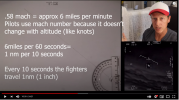
The easiest way to get some perspective on this is to note that the clouds never get any closer, even when the jet is heading directly for them at 240 kts.
It's difficult to wrap my head around. There's are very narrow field of view (0.75°). The object and the jet are both moving, and probably not in straight lines
Starting at frame 0 the clouds take 67 frames, or 2.23 seconds to cross the field of view, it's at a bit of an angle so that about 0.75° in 2 seconds, or 0.375°/sec
Starting at frame 400 it takes 103
600 - 758
Total cloud movement is about 6° to 7°. total camera rotation is 60° (54 to -6). So the camera rotates about 10x the rate the object is moving relative to the clouds, angularly.
In the first 300 frames (10 seconds), the heading changes from 54° to 40°, 14 degrees, or 1.4° per second. about 4.28 minutes for a full turn.
Air speed is 241 Knots, 277mph, so in 10 seconds the jet would have travelled 0.77 miles.
If we take the target position as essentially fixed (if it's far away), then the heading change is the actual turn rate of the jet and so would travel a circle of circumference 277/60/60*360/1.4 = 19.8 miles
Adding this all together in a VERY simple GeoGebra sim with a non-moving UFO seems to indicate the UFO is around 12-15 miles away
Here the circle is the path of the jet. The green line is the original line of sight to the UFO. The pink line is the Line of sight to the UFO, so the angle between them is the angular movement of the clouds behind the UFO. When the Jet moves though 60° the cloud angle moves about 6°
Notice the speed of movement of the pink line, it starts out moving smoothly, but then slows down and essentially stops as the Jet Heading (black arrow) crosses over it. Just like in the video.
This is making some gross simplifications about the turn rate and path of the jet, but I reckon it's in the ballpark.
Last edited: