Stress is put on the airframe when it experiences speeds past it's VD, the airframe is affected by flutter and then breaks shortly after.
How long is "shortly"? And how has this time period been determined?
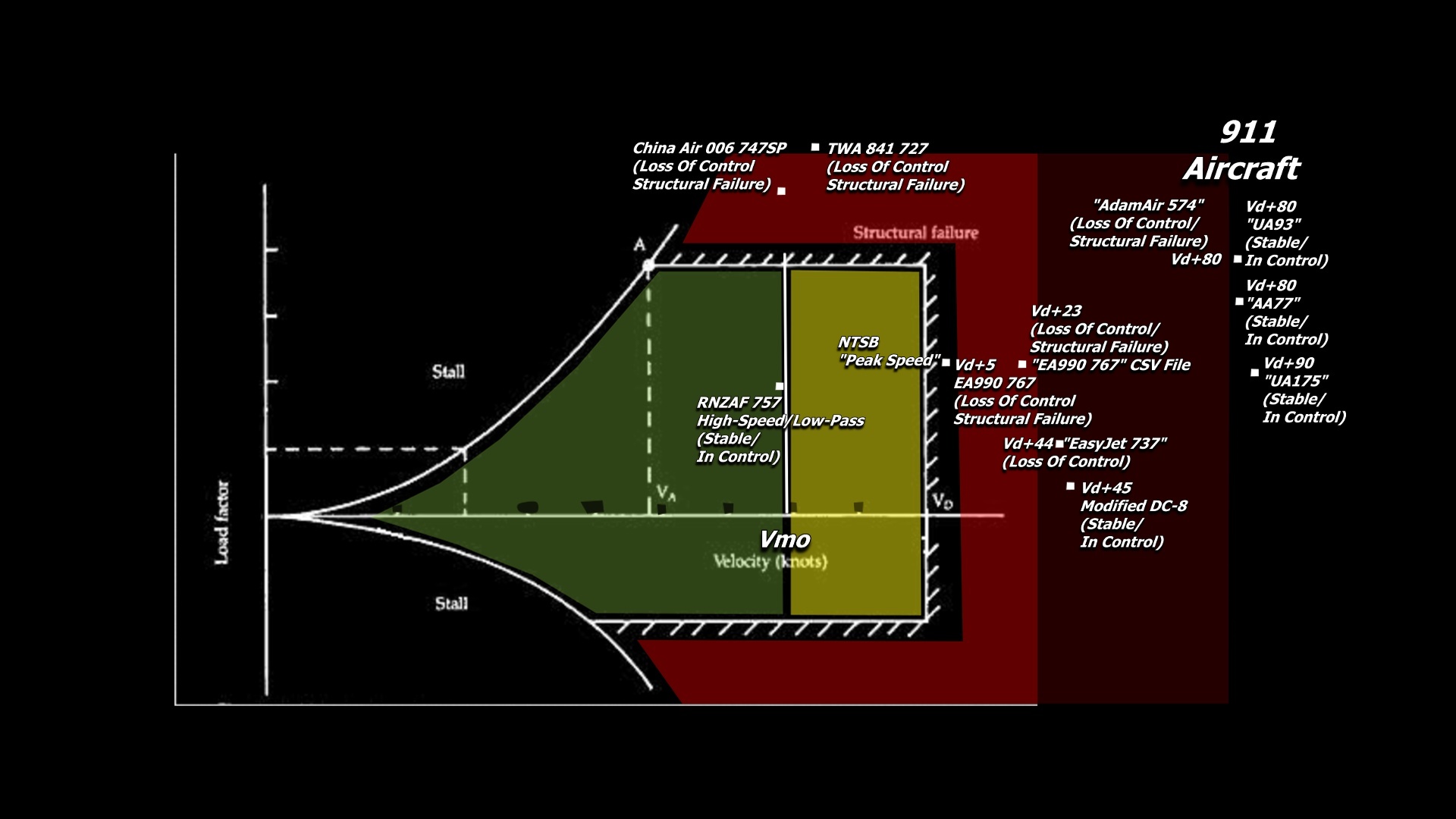
The NTSB calculated the peak speed experienced by the aircraft as a
value of 0.99 Mach, as the airplane descended through about 22,200 feet msl."
16 seconds after this peak speed was recorded, the FDR and CVR stopped working.
Why do we know it is because structural failure occurred, because the NTSB admits that.
"It is apparent that the left engine and some small pieces of wreckage separated from the airplane at some point before water impact because they were located in the western debris field about 1,200 feet from the eastern debris field."
the left engine and some small pieces of wreckage Separating before the whole of the aircraft impacted the water means they broke off the plane before the rest of the plane hit the water due to the peak speed of .99 mach recorded during it's dive.
What is it called when pieces of an aircraft break off in flight-
structural failure.
No speed indication, no reference as to how long the sample airframe was subjected to the airspeed it was experiencing before massive destructive flutter set in.
There was a speed indication, it was about
0.99 Mach, as the airplane descended through about 22,200 feet msl.
It was subjected to that speed for 16 seconds, as that is the period of time from the calculated peak speed and the FDR CVR and stopping their recording due to the structural failure.
How long is "shortly"? And how has this time period been determined?
See above
we must be looking at different reports then the report on the NTSB website lists oodles of evidence - FDR and CVR information, ATC info, reviews of actual wreckage, etc., etc.
You really should read page 118 of the NTSB report to find the Egyptian teams detailed rebuttal of their conclusions and the evidence they base them on.
...... including wind tunnel testing.
Except of course for the wind tunnel testing that was included - eg note 68:
Content from external source
68 Wind tunnel tests and computational fluid dynamics analyses show that a small sideslip angle and/or roll rate could produce large changes in the aerodynamic forces acting on the outboard ailerons at speeds approaching Mach 1.0, but these forces would not likely be strong enough to cause the split elevator condition recorded by the accident airplane.s FDR. For additional information, see Aircraft Performance . Addendum #1.1, Addendum to Group Chairman.s Aircraft Performance Study, including appendixes B and C (correspondence from Boeing, dated April 12 and 16, 2001).
Speeds approaching Mach 1 does not mean wind tunnel tests were done at speeds at mach 1, and the aircraft's peak speed was 0.01 away from Mach 1.
Read from page 118 of the NTSB report to find how their conclusion of how the split elevator condition occurred is flawed.
China Air 006 and TWA 841, for instance. The loss of control was pilot induced. Exacerbated by different circumstances. China Air crew were focused on an engine failure, allowed their airspeed to decay and didn't notice (due to the autopilot being in control) until the A/P reached its limit of control authority and disconnected. The asymmetrical thrust caused the yaw and roll and subsequent out-of-control dive. The "structural failure" did not result in a total failure of the airframe -- it landed safely, and was later repaired and returned to service.
Okay Proudbird, this is incredibly misleading, that aircraft
never went past it's vd, it only reached its VMO and did not even exceed it. So it's expected that the aircraft would not completely fail in flight, yet even still it experienced structural failure despite not even exceeding it's VMO and not even touching it's VD.
From Flight 006 NTSB Report
External Quote:
"Although the captain said that the airplane exceeded Vmo twice and also decelerated below 100 KIAS during the dive, all three crew members said that they did not hear the overspeed warning and that the stall warning stickshaker did not activate. Examination of the reliable recorded airspeed data points showed that the Vmo limitation was not exceeded during the descent. However, the recorder data does show airspeeds at or below 100 KIAS. The Safety Board cannot explain why the stall warning stickshaker did not activate, or if it did activate, why it was not felt or heard by the flightcrew."
This (also from the report) is the structural damage suffered by China Flight 006 despite not even exceeding it's VD and only reaching its VMO
External Quote:
All the damage found on the airplane occurred during the descent and was caused by aerodynamic overload forces.
Wings and Engine Pylons.--The wings were bent or set permanently 2 to 3 inches upward at the wingtips; however, the set was within the manufacturer's allowable tolerances. The left outboard aileron's upper surface panel was broken and the trailing edge wedge was cracked in several places.
Wing and Body Landing Gear.--The left and right wing landing gear uplock assemblies had separated from their attachment points on the fuselage structure. The interior skin and associated ribs on the left and right wing gear inboard doors were damaged in the vicinity of their striker plates and the striker plates also were damaged.
-13-
The doors were damaged in the area where the tires are located when the gears are retracted.
The left and right body landing gear uplock hooks were found in the locked-up position, but the fasteners of their uplock support bracket assemblies had failed at the attach points to the fuselage bulkhead.
The left and right body gear actuator doors had separated, but the forward lateral beams and associated door actuators had remained attached to their respective assemblies, and there were tire marks on the sections of structure attached to the lateral beams. (Note: The uplock assemblies hold the body gear in the retracted position after gear retraction is completed. Except for the body gear tilt assembly, which is pressurized by the No. 1 hydraulic system, the body gear actuators are unpressurized. The tilt assembly is pressurized and remains pressurized so that the body gear wheel bogies can enter or leave their wheel wells without their tires striking the forward wheel well structure.)
Empennage.--The major damage to the empennage was limited to the Auxiliary Unit APU) compartment, the horizontal stabilizers, and elevators. The APU had separated from its mounts and was resting on the two lower tail cone access doors. The forward side of the APU fire bulkhead appeared to be deflected forward in the area adjacent to the two lower attachment fittings and the two lower support rods had buckled. In the area of the APU, there were several punctures in an outward direction on both sides of the tail cone.
The aft pressure bulkhead was undamaged.
A large part of the left horizontal stabilizer had separated from the remainder of the stabilizer. The separated portion, which began at the outboard tip of the stabilizer, was about 10 to 11 feet long and included the entire left outboard elevator. The hydraulic lines from the No. 1 hydraulic system to the left outboard elevator actuator were severed near the actuator. (See figure 8.)
The right horizontal stabilizer incurred a similar separation. The separated portion included the entire tip of the stabilizer. However, beginning about 5 feet inboard of the tip, the separation moved directly aft to the area of the rear spar and then inboard an additional 5 to 6 feet along the forward edge of the box beam area. The separated portion of the stabilizer included the outboard three-quarters of the outboard right elevator. The hydraulic lines to the outboard elevator actuator remained intact. (See figure 8.)
Powerplants.--Except for some rotational scrubbing on the fan rotor rub strips of the Nos. 1 and 4 engines, none of the four engines were damaged during the accident. A boroscope examination of selected accessible areas of the No. 4 engine's front and rear compressors did not disclose any damaged areas.
TWA 841, although the crew denied it, consensus is (it gets technically complicated) but, let's say they were doing something not approved nor conventional. The loss of control involved another "high-dive" and speeds approaching Mach 1, and as with the China Air flight, excessive G-loads. Yet, even though some structural failure (the leading edge flaps...but THAT was the reason in the first place!) and the landing gear being extended at well above the maximum speed (gear door damage, not really structural...and IIRC the main gear struts were actually bent aftwards a bit), it landed safely, and was repaired and returned to service.
That aircraft did not exceed it's
VD, only it's
VMO/MMO by just 30 knots!
Yes the damage was repairable but still, the aircraft experienced structural failure despite not even exceeding it's VD,
which defines the "structural failure" zone where structural failure becomes imminent.
Merely two examples from the P4T "VG-Diagram" representation that are included on the graph in a disingenuous manner. Their inclusion is misleading and inflammatory.
No, they support the conclusions of P4T because they show that aircraft can still experience structural failure even when they experience speeds that are not even close to VD.
Yet, I am supposed to believe that UA93, UA175, and AA77 can
go far beyond the VD range,
remain in perfect control,
and not experience structural failure when two planes suffered structural failure when they were not even close to approaching their VD speeds.(Of course, that topic is not the debate here)
Now do you see why those flights are on the VG diagram?
Alas, the crux of the matter for a layperson.
"Pilots for 911 Truth" claims that any aircraft that exceeds VD will begin to suffer flutter and structural damage and could not possibly remain in flight.
Others cite instances in which aircraft were definitely outside the limits of design and yet either suffered no damage, or some damage but were repaired and returned to service after, of course, landing safely.
See above.
You should read through the thread again. They are there. Probably could be separated out though.
See above.
Flutter also varies greatly with the air conditions. In calm or laminar air it will occur at a much higher speed than in turbulent air. The testing for flutter is an incredibly complex thing nowadays - and actually has been pretty complex since the 1930s.
http://www.nasa-usa.de/centers/dryden/pdf/88390main_H-2077.pdf
The testing for flutter is an incredibly complex thing nowadays - and actually has been pretty complex since the 1930s.
You should know that VD is based on the onset of flutter by wind tunnel testing, the VD(flutter speed) for a 767 is 420 KCAS [from sea level] to 17,854 ft.
Meaning that at sea level to 17,854 feet , a 767 will experience flutter if it is beyond the range of 420 KCAS.
From the link - Bolds mine
<snip>
2 Flutter Clearance Philosophy
The method adopted for flutter clearance involved a combination of pre-flight flutter analysis and
flight flutter testing. The flutter analysis, has been used to identify the flutter characteristics of the aircraft
and establish broad trends over the flight envelope, and thereby provide guidelines for planning the
flutter tests, which includes the configurations to be tested, safe zone to start the tests, flight conditions at
which tests are to be carried out (i.e., flight test points), and the frequency range to be excited. The
analysis also told whether the primary clearance criterion which is the availability of a 15% speed margin
over the flutter speed (predicted 0% damping) was available for all critical modes. Since the existing
analysis tools do not cater to transonic speeds, this regime was cleared initially based on Wind Tunnel
test results using aeroelastically scaled models, and subsequently through flutter testing,
Flight Flutter tests are mainly aimed at demonstrating that the aircraft is free from flutter and
aeroservoelastic instabilities at all speeds in the flight envelope. Tests are progressively conducted by
increasing the velocity along the constant Mach number lines or Mach number/altitude increments along
constant CAS lines[1]. Tests are initially done in a region of the envelope where high stability is
predicted and subsequently extended to fully cover the envelope. The damping values obtained from the
results of these tests for any global structural mode should be within the limits laid out in the
airworthiness specifications/standards. Clearance was obtained on a "point by point" basis, by
computing the frequencies and damping coefficients (%g) of various global aircraft modes from the
flutter test data and ensuring that the damping coefficients are sufficient.
<<snip>>
3.3 Pre-flight Analysis
Flutter computations were carried out using a Finite Element model which was updated based on the
GVT results. The flutter analysis has indicated the following:
1) The MIL requirement of 15% margin in the flutter speed over the maximum design speed is met
at all altitudes.
2) The interaction between modes involving wing antisymmetric bending and antisymmetric wing
Outboard twist (caused by O/B CCM pitching) results in the lowest flutter speed. Since the
damping exhibits a gradual drop with airspeed, this is characterized as mild flutter, as is often the
case with wing-store flutter phenomena. However there is no cause for concern as the flutter
speeds are well beyond the flight Envelope.
MIL Requirement refers to a United States Military Standard, which means that a
requirement of a 15% margin in the flutter speed(VD) over the maximum design speed being met at all altitudes is only a requirement for military aircraft, which is what this document is referring to.
There is no evidence that that requirement is present in Boeing commercial airliners.
Such a requirement is also not present in FAR 25.335 which refers to design airspeed for transport category airliners.