My question is : what justifies making the Gimbal adjustments in that order during the calculations ? Does it work like that on a pod ?
You ask some very good questions. I started writing a post explaining why the choices we made were the right ones, realized we had gotten confused along the way, then dug around and learned something about ATFLIR that validates the choice we made after all (with one caveat, which I'll get to). The tl;dr of the story is: we do the rotation in the order pitch, then roll, because that order of rotations doesn't change the aircraft heading. To see why we want this, read on.
First, a small correction, so you won't get confused in what follows: yaw is a rotation about the vertical axis of the aircraft (like the pilot turning his head left and right), roll (not to be confused with pod roll) is a rotation around the longitudinal axis (like a steering wheel), and pitch is a rotation about the transverse axis (up and down from the pilot's perspective).
Take a rigid object in 3D space. It's a fact (that I'll state without demonstration) that you can rotate it into any orientation that you like by composing three rotations. There are different choices and conventions for what rotations are performed and in what order (you can read about them
here), but ultimately they're all equivalent. This means that you could do what we're doing here using a combination of pitch, yaw, and roll rotations in whatever order, so long as you choose the rotation angles appropriately.
So our choice is about what we can calculate, or estimate, given what we know about the problem. So what have we got? First, we know this is coordinated level flight. Secondly, we have bank angles, which can be tracked from the image, and we get to
estimate the angle of attack (which for the F-18 is the angle between the aircraft longitudinal axis and the flight path) using a simulator. You're right that we don't really know, and without a recording of the HUD or something we
can't know for sure because it depends on the aircraft weight and even loadout. Using DCS (a simulator which is generally considered to be accurate, at least in this gentle flight regime) we get an AoA of 6 degrees when heavy and 5 degrees when light. That said, DCS simulates the F-18C legacy hornet, while the gimbal video was shot with the F-18F Super Hornet. MSFS and a video I found of an FSX payware Super Hornet seem to suggest an AoA of about 4 degrees in similar conditions, so around 4 to 6 degrees is our ballpark.
So let's get a little airplane in the correct orientation for a level turn. Start from it wings level, pointing the nose straight at the horizon. I want to roll it so it matches the bank angle from the video and pitch it so it matches our estimated AoA. I claim we have to perform the rotations in the order
roll,
pitch. Why? Say we do the opposite: pitch, roll: then the aircraft will have an elevation angle matching the AoA, but the elevation has to be less than that because the airplane is in a bank, and performing the roll rotation afterwards will do nothing to the aircraft elevation. Here's some cartoons with some exaggerated angles (80 degrees of bank, 50 degrees of pitch) illustrating the difference between the two orders. The starting point:
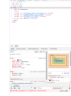
Notice how I'm in "local" rotation mode. This is so the axes get dragged around with the rotations, which makes it do what you intuitively expect when I say "pitch by x degrees, roll by y degrees). Now let's pitch the airplane up by 50 degrees:
And then roll by 80 degrees:
That's clearly not the attitude I would expect from an aircraft in level coordinated flight with a bank angle of 80 degrees and AoA of 50. It's more like some aggressive turning climb at some small AoA.
So let's do the opposite. First roll by 80 degrees,
and then pitch by 50 degrees:
Now that's the expected attitude. Wings are near vertical, taking a big bite out of the air. That's what this cartoon turn would look like.
Now notice that I mentioned that I'm using the "local" rotation mode in blender. That's what I didn't incorporate correctly; I simply multiplied by rotation matrices in the coordinate axes that corresponded initially with pitch and roll. In order to do it correctly, you simply apply the rotations in the reverse order. So for example with y the axis corresponding initially to pitch, and x the axis corresponding to roll, in order to get the airplane properly oriented you do the transformations in the order
pitch,
roll, that is,
y by 50 degrees, then
x by 80 degrees.
So that's how you get the aircraft oriented. What I did in my python script is to trace out the path the gimbal object would make in the sky
from the perspective of the pilots (and the ATFLIR pod), so you have to invert the above transformations, which means you apply the inverse of each step in reverse order: so
x by -80 degrees, then
y by -50 degrees, that is,
-roll,
-pitch!
This was the point when I thought I might've gotten it wrong. And since my intent was to do the transformation above, I did get it wrong. But somehow, I got to an answer that agrees with Mick's, and which I still claim is mostly right. How can that be?
So we've been working off some Navy documents that detail how ATFLIR is operated. In particular, A1-F18AC-746-100 states
External Quote:
Azimuth readout is the ATFLIR pointing angle left or right of aircraft ground track.
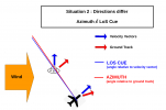
Now, to me, this never made any sense, at least for the Air-to-Air mode we're concerned with. It's adding a bunch of workload for the pilot who'll have to work out wind directions and speeds at whatever their altitude is in order to figure out where to go in order to find a target... that's probably subjected to the same wind he is anyway, so simply pointing the airplane towards him would be a much more expedient way to do it. So my assumption was that the manual was using imprecise language, and that the ATFLIR azimuths were referenced with respect to the horizontal projection of the aircraft velocity vector. This certainly makes more sense than it being the ground track, but if you think about it, ATFLIR is not just a thermal telescope, it's a component of a weapon system. The function of a weapon is to shoot things, in this case, missiles. If you want to shoot something like an AIM-9X at a target, you want to know how far off the aircraft boresight the target is to know if the missile can hit them or not. Furthermore, in an aircraft with integrated sensor systems, it'd be silly to have the FLIR pod and the radar work off different reference angles, and the radar azimuths are no doubt zeroed with respect to the boresight. So maybe the manual was right, but incomplete: perhaps the azimuths are referenced to the ground track when in air-to-ground mode, but to the boresight in air-to-air mode.
So I fired up DCS, turned on the ATFLIR, and did some sideslips while keeping an eye on what the pod does. Here it is in a/g (snowplow) mode,
And here it is in a/a (not tracking anything) mode:
It does just that -- in a/g mode, it keeps the pod pointing directly in front of the aircraft's trajectory, while indicating zero azimuth, while in a/a mode it doesn't move the pod at all, and the azimuth is locked at 0 regardless of the amount of slip. You can also see this in this
video, at 10m41s. During a level turn, the HUD shows the velocity vector pretty much exactly below the target, but the ATFLIR indicates it's pointing 1 degree to the right -- because there's some angle of attack during that level turn so the aircraft boresight is 1 degree to the left of its target.
Another source I found for this behavior is the manual for Jane's F/A-18 (attached). Of course, we don't know for sure whether the real Hornet works like this, but really it's the only thing that makes sense.
So, even though my initial code was (accidentally) right about how to transform the sky to match what the pilots would see, it started from the incorrect assumption that the indicated azimuths are referenced to the velocity vector, and so the pod is ahead of where it should be. That explains why that model looks better if delayed by a second or so. So to fix that, you run the transformations in an order that doesn't move the F-18's boresight laterally, so the reference remains correct. So that's why my revised code (accidentally) works, and why Mick's simulator also works.
Finally, the caveat: if doing the transformation in the order
pitch,
roll, the angle of pitch is not the angle of attack, but rather the elevation, the angle of the aircraft's longitudinal axis with respect to the horizon. In this case that's the projection of the angle of attack onto the vertical, that is, AoA * cos(bank). Since the AoA will have to increase with the bank angle to maintain level flight, using a constant elevation that's 85-90% of the real (but unknown) AoA is probably good enough. So that's the caveat -- the pitch we want to use is a touch smaller than the AoA estimated from the simulator.
(Incidentally, the assumption that the azimuths are referenced to the velocity vector was also made, often tacitly, by just about everyone who tried to work out the gimbal/gofast trajectory using the bank angles and indicated azimuths -- myself, Mick, Edward Current, Chris Lehto, Parabunk, etc. Those analyses might have to be revisited).