
You are using an out of date browser. It may not display this or other websites correctly.
You should upgrade or use an alternative browser.
You should upgrade or use an alternative browser.
9/11: Is this photo consistent with a progressive collapse?
- Thread starter lee h oswald
- Start date
- Status
- Not open for further replies.
The one you link to seems to be a different visualization for that segment. The high res one does not show the floors. They do use the visualization with the floors later, when showing the fuel.
Visualization is separate from the physical simulation.
ok. I make it 18 as well. And the 18th column is right at the tip of the wing in the first visualization, yes? In the first visualization there is no discernible damage after the eighteenth column. Would you agree?
If you could now do the same count for the second (zoomed-in) video
Last edited by a moderator:
Also 18. You can't see much beyond the 18th column, due to the closer crop.
18 as well, yes - plus there's a bit of a hole beyond that in this video, that isn't in the other one. There is some discernible damage beyond the 18th column and the strike of the port wing tip. Would you put this representation down to a better (higher definition) rendering? And the damage from the impact of the wing tip spreading to surrounding areas?
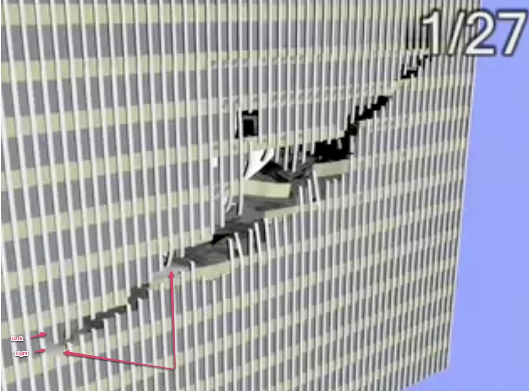
Here's the HD damage overlaid over the LD (low definition) image, so you can match the columns:
I think the damage beyond the 18th column is there in the LD version as well, there is some lighter grey material behind that shows through, but it's somewhat visible in this image:
I think the damage beyond the 18th column is there in the LD version as well, there is some lighter grey material behind that shows through, but it's somewhat visible in this image:
Last edited:
That's great. Can you overlay the aircraft onto that? As the wingtips pass through the perimeter?Here's the HD damage overlaid over the LD (low definition) image, so you can match the columns:
I think the damage beyond the 18th column is there in the LD version as well, there is some lighter grey material behind that shows through, but it's somewhat visible in this image:
Last edited by a moderator:
If you explain what you are getting at, then I'd be happy to help. But I don't really see where this is going.
Sorry, I know it's a pain, but this really is the last one...then we can move along
Here are the two clips frame synchronized. They are exactly the same (in terms of the order, number and nature of exterior column damage):
No, because I've no idea what you are looking for so I don't know if I'm wasting my time. Explain, and I'll help.
Fair enough. The above video will do - at 5 seconds, freeze frame and you can do the same count. I'll agree that the damage beyond the 18th column is visible in the lower def video, the wing tip seems to reach just beyond the 18th and last severed column. Can we agree on that?
I agree with that. But what's your point?
My point is the same as it was in all the discussions we've previously had about this presentation. That it is wrong; that it is a blatant lie; that some people got together and lied about the science; that there is no visible deformation or damage on the aircraft at the first moment of impact with the perimeter columns as you would expect; that there is no specifiic deformation or damage to the a/c coming into contact with the perimeter is counter-intuitive and counter to Newton's third law (that every action has an equal and opposite reaction); that the people responsible, if they were ever held to account for this misrepresentation, might find they were guilty of a conspiracy to pervert the course of justice; that it is most definitely not a 'high quality' high-fidelity' 'scientifically accurate' rendering of the event (it might well be 'state-of-the-art' in terms of the equipment used, but all the more trouble for the makers if that is indeed the case); despite all these claims, it does not offer an accurate portrayal (supposed to be 'eloquent to the non-expert user', as the narrator tells us) of the event.
The people responsible for creating this presentation should be ashamed of themselves. Maybe, one day, they will have to answer for the lie they have told.
Those don't represent the exact same instant, as far as I can tell. I'd have to create a synced version of the clips. Maybe later, if you explain what the discrepancy is.
Sorry about the problem's uploading, I think that was my fault, as some of the image types had very low size limits. I've upped them all to 10MB now, so if you'd like to try again it should work.
They don't represent the same instant, that's not my point. The point is coming.
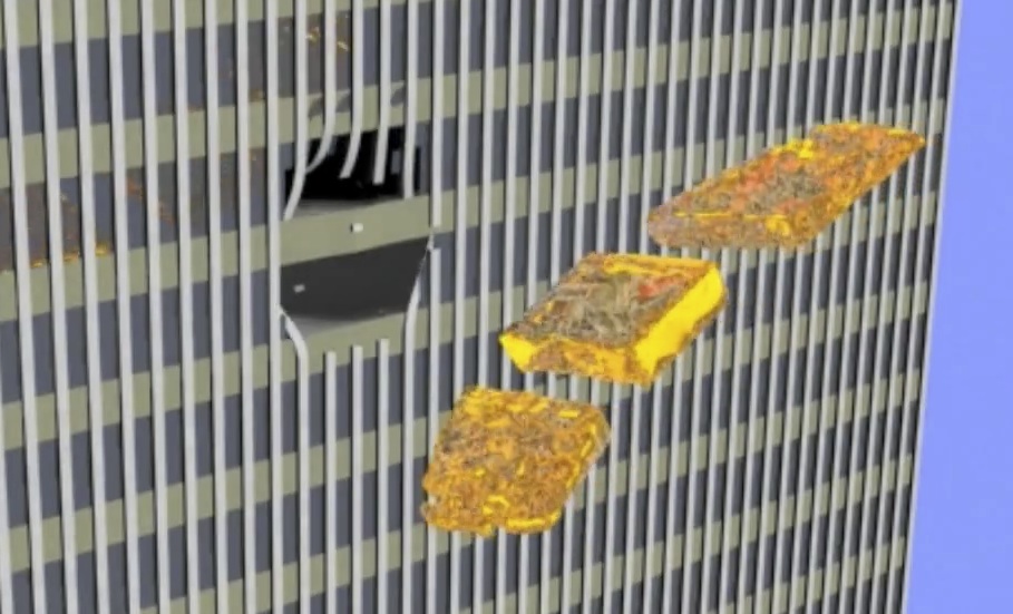
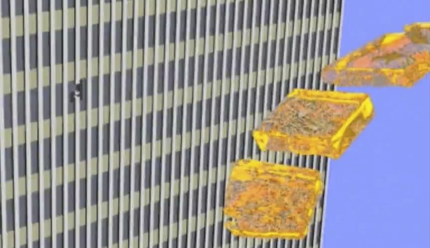
This still from the video is a little further advanced than the one I was looking at, but no matter. What it represents is the fuel tanks in the aircraft. If you play the video you can see (and just about in this still) that there are three full tanks of fuel, two in the wings and one central. Agreed?
Last edited by a moderator:
They don't represent the same instant, that's not my point. The point is coming.
This still from the video is a little further advanced than the one I was looking at, but no matter. What it represents is the fuel tanks in the aircraft. If you play the video you can see (and just about in this still) that there are three full tanks of fuel, two in the wings and one central. Agreed?
There's three fuel tanks, they look fairly full.
Last edited:
When I have finished with falsifying this Purdue simulation that so many people went to so much trouble to produce, and that you once held up as evidence, will you take a different stance to it? Will you never use it again as evidence? Will you debunk it? Will you use your not inconsiderable intellect to demolish it for what it is - a lie?
there is no visible deformation or damage on the aircraft at the first moment of impact with the perimeter columns as you would expect; that there is no specifiic deformation or damage to the a/c coming into contact with the perimeter is counter-intuitive and counter to Newton's third law (that every action has an equal and opposite reaction);
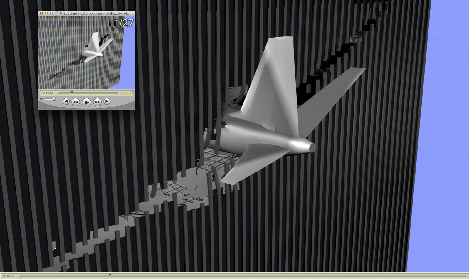
But there IS damage to the leading edge of the wing. It's at the front of the wing, and you are viewing it from behind. Look at it from the front:
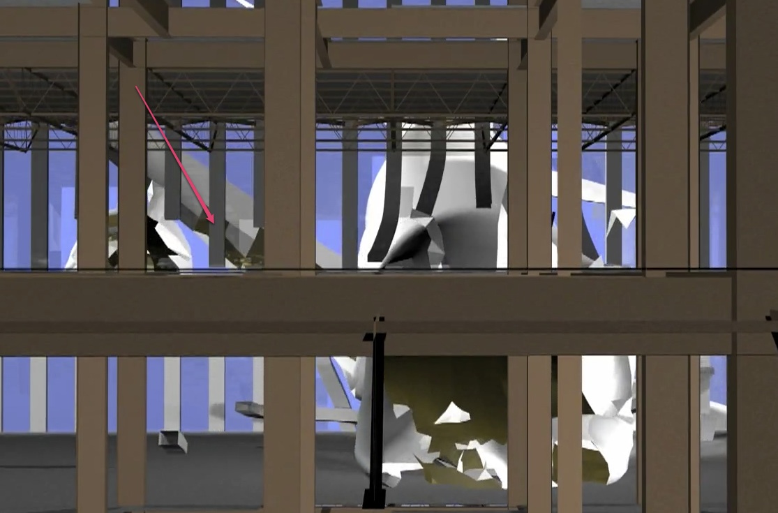
Here the indicated column has yet to break, and the wing behind it had been visibly deformed (hard to see in the low resolution video from behind and above).
The front of the plane and the engine have quite obviously deformed.
Last edited:
When I have finished with falsifying this Purdue simulation that so many people went to so much trouble to produce, and that you once held up as evidence, will you take a different stance to it? Will you never use it again as evidence? Will you debunk it? Will you use your not inconsiderable intellect to demolish it for what it is - a lie?
If you do falsify it, then we can discuss how to proceed. But you are taking a very long time to arrive at your point.
If you debunk it, then it's debunked. What would remain for me to debunk?
Anyway, please proceed.
Three full tanks. Good. If you go to http://www.nist.gov/manuscript-publication-search.cfm?pub_id=101356 and click on the pdf link, you will end up here http://www.nist.gov/customcf/get_pdf.cfm?pub_id=101356 which is the document NIST NCSTAR 1-5A where, on page 79, you can find NIST saying that the centre fuel tank of AA11 was empty.There's three fuel tanks, they look fairly full.
Who got it wrong? NIST or Purdue?
Add to that: at this moment in the video, we should (with the aircraft 'switched-on' to visuals) see a specific deformation relating to the spandrel which has not yet broken - the a/c nose has presumably been split in two by this large steel element and we should be seeing peeled aluminium skin, exposed airframe etc. as the tube is split by the harder steel elements. The video doesn't depict that.
Last edited by a moderator:
Those don't represent the exact same instant, as far as I can tell. I'd have to create a synced version of the clips. Maybe later, if you explain what the discrepancy is.
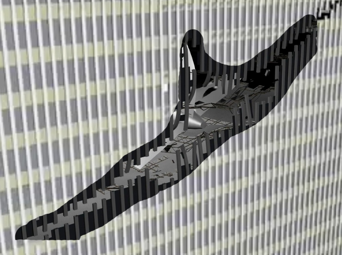
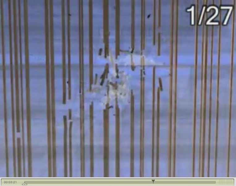
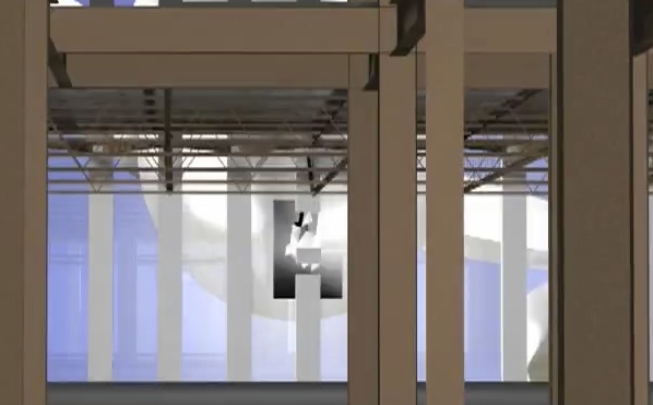
And last - the core. This image relates only to alleged damage to the core columns.
The a/c has been largely 'switched off' via the visual controls of the simulation - it is partially visible in the moving video, but very hard to see in the still image here. What is easy to see is the cut core column about 3/4 of an inch from the left of the screen and about an inch and a half up from the bottom of the screen. In the visualization, this column is clearly cut by the port wing.
Can you begin to see where support for Purdue might begin to unravel?
Last edited by a moderator:
Three full tanks. Good. If you go to http://www.nist.gov/manuscript-publication-search.cfm?pub_id=101356 and click on the pdf link, you will end up here http://www.nist.gov/customcf/get_pdf.cfm?pub_id=101356 which is the document NIST NCSTAR 1-5A where, on page 79, you can find NIST saying that the centre fuel tank of AA11 was empty.
Who got it wrong? NIST or Purdue?
Likely Purdue. Unless they later got information that there was fuel in the center tank. But I can't find anything to suggest that.
They do, however still model the correct amount of fuel (9118 Gallons, NIST says "About 10,000 gallons", equally split.), so what would change would be the distribution of mass. This would suggest that the simulation would underestimate the damage caused by the inner portion of the wings, and overestimate the damage around the centerline (which would mostly affect the damage profile to the core). Although as the 9118 is a it lower than 10,000, it's also underestimating the total kinetic energy.

Add to that: at this moment in the video, we should (with the aircraft 'switched-on' to visuals) see a specific deformation relating to the spandrel which has not yet broken - the a/c nose has presumably been split in two by this large steel element and we should be seeing peeled aluminium skin, exposed airframe etc. as the tube is split by the harder steel elements. The video doesn't depict that.
I'm not sure what you mean there, the aircraft nose is quote clearly ripped to pieces in the simulation. It's not that obvious from behind, but viewed from the front it is.
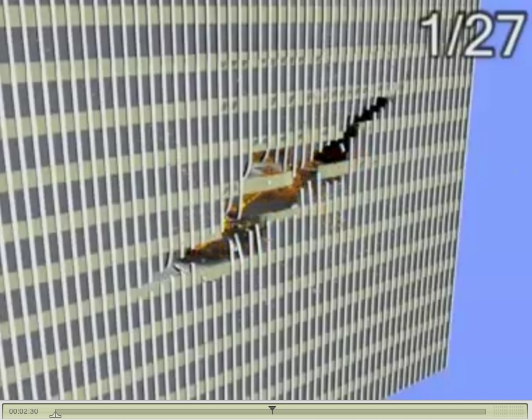
This is the first frame of impact:
Last edited:
And last - the core. This image relates only to alleged damage to the core columns.
The a/c has been largely 'switched off' via the visual controls of the simulation - it is partially visible in the moving video, but very hard to see in the still image here. What is easy to see is the cut core column about 3/4 of an inch from the left of the screen and about an inch and a half up from the bottom of the screen. In the visualization, this column is clearly cut by the port wing.
Can you begin to see where support for Purdue might begin to unravel?
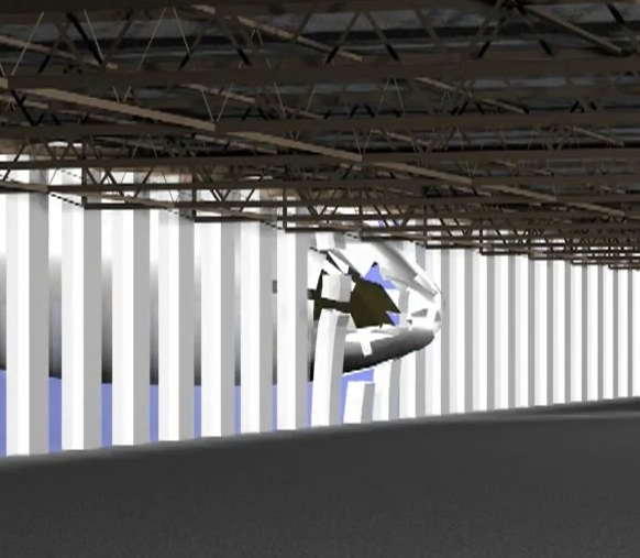
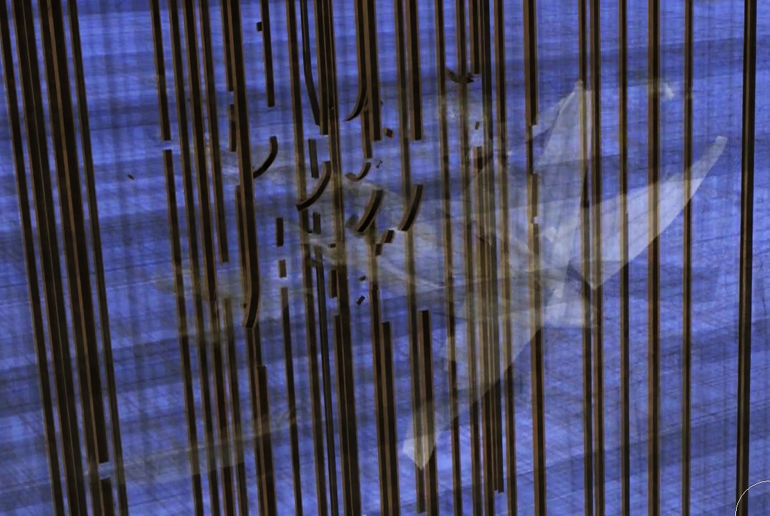
Here's an enhanced version:
Are you saying that's physically impossible?
Last edited:
There's three fuel tanks, they look fairly full.
Ok. Let's quickly rewind to where I led you to agree to
I apologise for this sleight of hand, but it is an issue of psychology. This image clearly shows that the port tank is at about half the capacity of the starboard tank. I just wanted to demonstrate how easy it is to trick the human mind - even one that is switched on to the subject.there are three full tanks of fuel, two in the wings and one central. Agreed?
The fact is that Purdue represented this part of their visualization inaccurately. They obviously put the wrong data into the simulation, it is clear. It is wrong.
Last edited by a moderator:
There's three fuel tanks, they look fairly full.
This image is contradicted by this one
I'm not sure what you mean there, the aircraft nose is quote clearly ripped to pieces in the simulation. It's not that obvious from behind, but viewed from the front it is.
Because in this image the nose is in between two floors, and in the image above, the a/c has gone either side of the spandrel/floor. It doesn't appear to represent the same image from different angles at all.
Further to that, and as an aside to the main point above, I say there should be a specific deformation relating to this visible from the outside view - taking into account Newton's third and the second law of thermodynamics which says that any disorder is likely grow over time...in other words, the peeling of the fuselage and its contents should be visible in advance of the a/c entering the building due to the forces being impressed upon the structure of the a/c by the floor/spandrel - what do you think?
Last edited by a moderator:
Leifer
Senior Member.
Did anyone involved in the study not notice what what you are saying ?....unable to notice that they were wrong ?
After all....they had figures and numbers.
You on the other hand, have visualization as your tool, as well as a certain bias. Combine visualization + bias, and the result is easily far away from the results found with their figures and numbers.
Their "visualization" (animation) .....yes, had biases based on the input data being fed to them. But it seems you then take their generalized animation, to mean it is 100% literal.....you can't do that. The animation is just that....an "animation" to plainly describe the detailed circumstances of that day.
If I animate an image of a pear (fruit) in a computer rendering....certainly you could say, "but it's still not a pear".......and you'd be right.
The fact is that Purdue represented this part of their visualization inaccurately. They obviously put the wrong data into the simulation, it is clear. It is wrong.
Yes it's wrong, but the question is how much of an effect this fuel distribution error would have on the overall results. Clearly it would mean the specifics would be incorrect - but then even a small variation in initial parameters would mean the end result would be different. It's like a break in pool. The balls go all over the table, but it's hard to predict where they end up. And no simulation of a break is going to match a physical break, no matter how well you measure the initial positions and velocities.
I think you expect too much from a simulation. It's not saying "this is exactly what happened", but "this is the type of thing that could plausibly have happened, given what we know".
And last - the core. This image relates only to alleged damage to the core columns.
The a/c has been largely 'switched off' via the visual controls of the simulation - it is partially visible in the moving video, but very hard to see in the still image here. What is easy to see is the cut core column about 3/4 of an inch from the left of the screen and about an inch and a half up from the bottom of the screen. In the visualization, this column is clearly cut by the port wing.
Can you begin to see where support for Purdue might begin to unravel?
I should also point out that the beams which connected the core columns to each other (horizontal and diagonal steel elements, bolted and welded to each other) are also 'switched off' in this section, giving the impression that the core columns are free-standing and very skinny. They most definitely were not.
Leifer
Senior Member.
This image is contradicted by this one
Because in this image the nose is in between two floors, and in the image above, the a/c has gone either side of the spandrel/floor. It doesn't appear to represent the same image from different angles at all.
It's not different. If you look closely at the images....the front fuselage tip penetrates the upper half of one floor, then engages the horizontal beam, then as it enters, it plows through that vert beam, and then the above lower floor too.
The point of entry may have been the lower floor....(the central forward point of the aircraft). But the slope of the aircraft's nose rises upward more abruptly than it's lower portion, which is of a flatter nature.
You are comparing to different moments in time. Look at the initial point of impact:This image is contradicted by this one
Because in this image the nose is in between two floors, and in the image above, the a/c has gone either side of the spandrel/floor. It doesn't appear
to represent the same image from different angles at all.
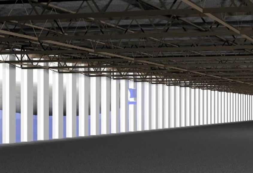
It's exactly the same.
Further to that, and as an aside to the main point above, I say there should be a specific deformation relating to this visible from the outside view - taking into account Newton's third and the second law of thermodynamics which says that any disorder is likely grow over time...in other words, the peeling of the fuselage and its contents should be visible in advance of the a/c entering the building due to the forces being impressed upon the structure of the a/c by the floor/spandrel - what do you think?
I think it does, but because of the scale, this deformation does no travel very far back along the plane. The simulation is of limited effective resolution - you see how things break in large chunks, often into squares and triangles, so it's not going to look perfect at every level.
(And I really don't think the second law of thermodynamics has anything to do with it).
Last edited:

Here's an enhanced version:
Are you saying that's physically impossible?
Given all the evidence available - yes. I would say that it is as near physically impossible as I can say without being absolutely sure, ie. by being a first-hand witness to the event.
Last edited by a moderator:
Leifer
Senior Member.
It's your "assumptive thinking" that's getting in the way......not by my postings here.Given all the evidence available - yes. I would say that it is as near physically impossible as I can say without being absolutely sure, ie. by being a first-hand witness to the event.
Nobody is "positively sure" of anything, 100%. Too many tiny variables. But the overall explanation (animation) covers most of it.
I'm not sure why you think the vast majority of engineers' opinions who agree with NIST, or the animation....is false? .
Perhaps take the matter up with engineers and airline designers....then get back with us.
Correct me if I'm wrong....but there is more structural strengthening in the upper nose-cone of the 767, than the lower portion of the 767 nosecone.
View attachment 505
At risk of being impolite: wtf are you talking about? Just stay still and watch. You are defending something without knowing what it is.
Correct me if I'm wrong
It's your "assumptive thinking" that's getting in the way.........the overall explanation (animation) covers most of it.
I'm not sure why you think the vast majority of engineers' opinions who agree with NIST...the animation....is false? .
Perhaps take the matter up with engineers and airline designers....then get back with us.
Oh yeah? Keep talking. The more you speak, the less you know.
Given all the evidence available - yes. I would say that it is as near physically impossible as I can say without being absolutely sure, ie. by being a first-hand witness to the event.
That section of the wing is still several tons of very strong aluminum alloy travelling at several hundred miles per hour hitting a column at its shear point (the base of a vertical section). It does not seem entirely implausible that it might fail. At least get severely damage. The end of the column snapping off seems a bit unintuitive. More likely it would just separate and bend - but intuition might not be best metric here.
Nobody is "positively sure" of anything, 100%.
I am positively sure, 100%, that I just ate curried noodles with stir fry veg and a nice bit of monkfish poached in a court bouillon. I'm pretty sure I ate it, I cooked it so I might as well have... it was nice.
Did anyone involved in the study not notice what what you are saying ?....unable to notice that they were wrong ? After all....they had figures and numbers. You on the other hand, have visualization as your tool, as well as a certain bias. Combine visualization + bias, and the result is easily far away from the results found with their figures and numbers. Their "visualization" (animation) .....yes, had biases based on the input data being fed to them. But it seems you then take their generalized animation, to mean it is 100% literal.....you can't do that. The animation is just that....an "animation" to plainly describe the detailed circumstances of that day. If I animate an image of a pear (fruit) in a computer rendering....certainly you could say, "but it's still not a pear".......and you'd be right.
I think you should go and animate a pear
Or
What?!
Leifer
Senior Member.
I am a good cook, so i will have to ask you these questions.....that you are so sure of......as an analogy (sounds yummy what you ate. btw)......
"curried" means what ?
-Indonesian curry ?
-South-asian curry ?
-Japanese curry ?
....see the reason for specifics ? I have no idea what type of "curry" you are speaking of. "Curry" is a western term, usually applied to a mixture of spicy and savory herbs attributed to eastern cooking. Ask an Indonesian what "curry is", and you'll either get a mystified look, or any concoction of various herbed recipes.
"Court Boullion" is presented differently in areas of France.....so Herbes de' Provence may depend on the region in which grown/cooked, and in the season in which it is prepared..
While you think you ate something 100% explainable....you really did not.
That section of the wing is still several tons of very strong aluminum alloy travelling at several hundred miles per hour hitting a column at its shear point (the base of a vertical section). It does not seem entirely implausible that it might fail. At least get severely damage. The end of the column snapping off seems a bit unintuitive. More likely it would just separate and bend - but intuition might not be best metric here.
That section of the wing is still several tons of very strong aluminum alloy travelling at several hundred miles per hour
No it isn't. Not after colliding with the perimeter. After that it is significantly reduced in mass - or into much smaller masses - by then it is also travelling at a slower speed due to the inconvenience of the perimeter columns.
this is a fallacy. You need to think about how a column might be given a problem - where it is close to a junction with other steels which are tied to it via welding and bolts, you need to consider the amount of leverage a blow to that section might impart to the welds and the bolts and when you look at this in detail, you'll find that a blow to the centre of the column/beam would impart more energy on those couplings. It is also worthy of note that the bolt connections of steels have a higher tensile strength than the steels themselves. This is all easy to research.hitting a column at its shear point (the base of a vertical section)
The end of the column snapping off seems a bit unintuitive. More likely it would just separate and bend - but intuition might not be best metric here.
I agree that intuition is not necessarily the best metric here - but it is a useful one. I presume that you do not see the Purdue visualization as falsified? How would you sum up what I have so far shown?
- Status
- Not open for further replies.
Similar threads
- Replies
- 101
- Views
- 22K
- Replies
- 59
- Views
- 4K
- Replies
- 28
- Views
- 5K