Isn't the boresight just the physical orientation of the pod lateral and vertical axes of the pod, which corresponds to the view when the gimbal has zero offset? The optics and the Gimbal allow the pod to look at objects that are off boresight. The magnitude of the offset from the boresight can be different in each axis, so they do not have to be the same.So if they are both relative to boresight, how can they be different ? Or the cue is not very precise ?

You are using an out of date browser. It may not display this or other websites correctly.
You should upgrade or use an alternative browser.
You should upgrade or use an alternative browser.
Calculating and visualizing Gimbal angles.
- Thread starter markus
- Start date
jarlrmai
Senior Member.
Typically in normal guns bore-sighting is the alignment of the sighting device with the barrel, in a fighter jet aircraft this could mean a few things, the alignment of the ATFLIR (sighting device) of the unlaunched missile currently selected, or the nose of the aircraft.
DavidB66
Senior Member.
I don't follow this. Surely for most of the (short) video the Navy plane is turning in a tight circle, while the object is not, so 'the directions of each object against the wind' must be different during most of the video. So why does the divergence only occur at the very end?The fact that azimuth and Los Cue diverge at the end of the video means that the directions of each object against the wind are different, which is contradictory with the fighter seeing the rear of a plane.
Also, if the speed and/or direction of the wind itself are different for the two objects, this would be more likely if the object is relatively far away from the Navy plane, where wind conditions are more likely to be different. In any case I don't see how this is contradictory with 'the fighter seeing the rear of a plane', as distinct from seeing any other object that is subject to the laws of physics.
The DCS F18 manual also says :
Situational Awareness Cue. This diamond moves left or right from center to indicate that the pod has a left or right azimuth offset from boresight. The diamond moves up or down to indicate that the pod has an up or down elevation offset from boresight. When boresighted, the diamond is centered laterally and close to the top of the display. The extreme edges of the display roughly correspond to the slew limits of the pod. The diamond is centered vertically on the screen when the pod is pointed straight down.
So if they are both relative to boresight, how can they be different ? Or the cue is not very precise ?
I'm not really sure about this, but I think it's possibly because when Az = 0 on screen (30.3 seconds), the bank angle of the jet puts the target to the left of the centerline of the jet by a combination of the target elevation angle and the angle of attack. And this pans out at other Az values.
Elevation set to -8 here, to visualize the effect.
Green dot is the target, Az = 0, but if we rotate the scene so the wings are horizontal, the target is under the left engine, i.e. it's still a bit to the left.
The white line is the target track, notice it crosses the horizontal plane of the jet at about the same point the Az and Cue cross over (this isn't a good example as we are at -8° elevation, but there's the same effect with El = -2, and a larger AoA)
If the jet were not banked, then the cue dot would be the same as Az.
Need to look at this a bit more...
Last edited:
To clarify (partly for me) what I'm saying above, we have the Az angle, and the Cue Dot Angle

With the plane banking left, the Cue dot angle, measured from the middle of the screen (the center of the bars) is a bit ahead of Az, then equal, then behind.
This difference seems to be consistent with the Cue angle being measured in the frame of reference of the jet, i.e. it the angle you'd need to turn the nose of the jet in the plane of the wings to point at the target.
This differs from the Az value, which, like radar Az values, is a horizontal angle. i.e the angle you'd need to turn the nose of the jet in the horizontal plane to point at the target.
Additional evidence for this is the observation that the Cue angle changes differently when the plane's bank angle is changing.
This might be something that someone could verify in DCS.
TheCholla
Senior Member
I don't follow this. Surely for most of the (short) video the Navy plane is turning in a tight circle, while the object is not, so 'the directions of each object against the wind' must be different during most of the video. So why does the divergence only occur at the very end?
Also, if the speed and/or direction of the wind itself are different for the two objects, this would be more likely if the object is relatively far away from the Navy plane, where wind conditions are more likely to be different. In any case I don't see how this is contradictory with 'the fighter seeing the rear of a plane', as distinct from seeing any other object that is subject to the laws of physics.
Ok let me explain what I mean using the schematic I posted above, but this time applied to the two options we have refined for explaining the video.
First, lets's consider the case of the object being before the intersection point of the LoS
Here is what would happen in terms of horizontal angle relative to ground track, and relative to boresight, at the beginning of the video (Point 1), and the end of the video (Point 2).
This divergence between the two measured angles diminishes as the planes banks and its direction align with the velocity vector of the Gimbal object. Then their directions diverge again. And at the end of the video (Point 2 here), the wind deviates the fighter to the left, making for a greater R azimuth angle when relative to the ground track, versus the local velocity vector. This is exactly what we see in the video, if the dot cue gives the local azimuth angle, and the number gives the ground track azimuth angle. This what Mick found when comparing the azimuth angle from the cue dot with the displayed azimuth angle.
Second, lets's consider the case of the object being after the intersection point of the LoS
At the beginning of the video, we have the same effect as in the previous scenario, the azimuth angle relative to ground track is greater than the azimuth angle relative to local velocity vector (greater L angle). However, if at the end the planes velocity vectors are aligned, the azimuth angles between ground track and local velocity vectors will be equal, as the wind deviates their velocity vector in the same way. We should see a gradual decrease in the divergence between the two azimuth angles.
Now, this is quantitative only, and we could go into more detailed calculations to get rough estimates of the amplitude of divergence in azimuth angles due to this effect. But the fact that this mechanism aligns with the divergence we see in the azimuth angles in the case of scenario 1 is at least troubling.
TheCholla
Senior Member
With the plane banking left, the Cue dot angle, measured from the middle of the screen (the center of the bars) is a bit ahead of Az, then equal, then behind.
This difference seems to be consistent with the Cue angle being measured in the frame of reference of the jet, i.e. it the angle you'd need to turn the nose of the jet in the plane of the wings to point at the target.
This differs from the Az value, which, like radar Az values, is a horizontal angle. i.e the angle you'd need to turn the nose of the jet in the horizontal plane to point at the target.
Additional evidence for this is the observation that the Cue angle changes differently when the plane's bank angle is changing.
This might be something that someone could verify in DCS.
Ok I'll have to think about this more because I'm not sure I follow. I think it's critical to clarify what is the local azimuth angle here.
Leonardo Cuellar
Active Member
I had already analyzed this behavior and it was my strongest doubt.Ok I'll have to think about this more because I'm not sure I follow. I think it's critical to clarify what is the local azimuth angle here.
The LOS cue is an angle that lies on the horizontal plane of the aircraft. The azimuth of the pod instead lies on the plane of the horizon. When the aircraft tilts a bank angle, the pod angle projection generates an angle on the plane of the aircraft differently. If there is also a pitch angle, it changes further.
In the specific case that I have analyzed in gimbal, that is with pod azimuth -4°, bank angle 30° and a possible pitch angle of 5°, the corresponding angle on the horizontal plane of the aircraft should be even greater, i.e. about 7.5°. This simple diagram illustrates the geometric representation. The aircraft pointing towards the drawing is depicted in red. The angles are obviously exploded to be able to represent them in 2D.
TheCholla
Senior Member
To clarify (partly for me) what I'm saying above, we have the Az angle, and the Cue Dot Angle
View attachment 49628
With the plane banking left, the Cue dot angle, measured from the middle of the screen (the center of the bars) is a bit ahead of Az, then equal, then behind.
This difference seems to be consistent with the Cue angle being measured in the frame of reference of the jet, i.e. it the angle you'd need to turn the nose of the jet in the plane of the wings to point at the target.
This differs from the Az value, which, like radar Az values, is a horizontal angle. i.e the angle you'd need to turn the nose of the jet in the horizontal plane to point at the target.
Additional evidence for this is the observation that the Cue angle changes differently when the plane's bank angle is changing.
This might be something that someone could verify in DCS.
Ok I get what you're saying, it makes sense too. This would be a better explanation than the azimuth being relative to ground track because it fits the manual. What I don't get is why this effect increases at the end when the bank angle in fact diminishes.
Whatever is the cause for it, I'm happy because this new information finally explains why the minimum of cloud motion is after passing the azimuth. The pod actually has the target in its boresight later than suggested by the azimuth.
Last edited:
TheCholla
Senior Member
@Leonardo Cuellar , could you please explain a bit more what you mean ? What about if you look at different points in the video, do they align better ?I had already analyzed this behavior and it was my strongest doubt.
The LOS cue is an angle that lies on the horizontal plane of the aircraft. The azimuth of the pod instead lies on the plane of the horizon. When the aircraft tilts a bank angle, the pod angle projection generates an angle on the plane of the aircraft differently. If there is also a pitch angle, it changes further.
In the specific case that I have analyzed in gimbal, that is with pod azimuth -4°, bank angle 30° and a possible pitch angle of 5°, the corresponding angle on the horizontal plane of the aircraft should be even greater, i.e. about 7.5°. This simple diagram illustrates the geometric representation. The aircraft pointing towards the drawing is depicted in red. The angles are obviously exploded to be able to represent them in 2D.
View attachment 49634
DavidB66
Senior Member.
Thanks for the explanation. I doubt that I fully understand it, but I hope it will be useful to others.At the beginning of the video, we have the same effect as in the previous scenario, the azimuth angle relative to ground track is greater than the azimuth angle relative to local velocity vector (greater L angle). However, if at the end the planes velocity vectors are aligned, the azimuth angles between ground track and local velocity vectors will be equal, as the wind deviates their velocity vector in the same way. We should see a gradual decrease in the divergence between the two azimuth angles.
I don't see a huge problem in the divergence right at the end of the video. Isn't it agreed that the fighter 'overshoots' the target in the final few seconds, as shown by the angle of the pod turning to R? At 0:33 the ATFLIR seems in danger of losing its lock on the target. I don't know if the overshoot was accidental, or if the intention was always to overshoot and then correct it if necessary. I note that the banking angle of the fighter at the end of the video is still quite steep. As a non-pilot (even on simulators!) I would have expected that if the intention was not to overshoot, the pilot would have leveled out earlier.
Leonardo Cuellar
Active Member
This is the geometric explanation of why the angle generated by the LOS cue increases or decreases with the bank angle as observed by Mick in his tool. In the condition where the azimuth is on the raised wing side, the LOS cue angle will be even larger than the azimuth angle. So it is still not explainable because instead at -4° on the right the pilot sees the object exactly in front of him. Certainly not for this reason.@Leonardo Cuellar , could you please explain a bit more what you mean ? What about if you look at different points in the video, do they align better ?
TheCholla
Senior Member
Situational Awareness Cue. [...] The diamond moves up or down to indicate that the pod has an up or down elevation offset from boresight. [...] The diamond is centered vertically on the screen when the pod is pointed straight down.
EDIT : it's way up at the end, can that help determining the angle of attack ?
EDIT : it's way up at the end, can that help determining the angle of attack ?
Last edited:
Leonardo Cuellar
Active Member
If you mean the reason why the point approaches and moves away from the center in the GOFAST video is because there are higher elevation angles than in GIMBAL.Situational Awareness Cue. [...] The diamond moves up or down to indicate that the pod has an up or down elevation offset from boresight. [...] The diamond is centered vertically on the screen when the pod is pointed straight down.
The vertical movement of the cue is also interesting, because it gives an idea of the AoA changes right ?It goes up despite no change in elevation readout (-2deg). Which means the angle of attack decreases ? If at the end it's all the way up (0deg vertical angle from boresight), does that mean the AoA is -2 during the rotation segment of the video ?
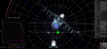
Look at this graph:
Treat the red circle as a sphere. The green line is the elevation vector. The blue line is the extension of the projection of the intersection point of the elevation with the red sphere. The brown diamond is the point where the projection intersects the aircraft's horizontal plane.
Now consider that the plane is tilting at a bank angle.
The aircraft's horizontal plane will now be represented by the yellow line. The yellow diamond is the point on the aircraft's horizontal plane where the blue extension of the elevation vector intersects it. As you can see by tilting the plane the LOS cue moves away from the center.
This is not visible in GIMBAL because the elevation is very close to the plane's horizontal plane.
TheCholla
Senior Member
Thanks @Leonardo Cuellar , it explains why the cue dot moves sharply towards the edge when the plane is banking in GoFast.
Looking at Gimbal, I think the vertical change of the cue dot is reflecting changes in AoA of the plane. At the end the cue dot is all the way up, meaning there is positive offset if I understand the manual correctly. Looking at Mick's simulator, during the rotation I can only get positive offsets from the plane boresight with negative AoA. Negative AoA makes quite a difference in the Gimbal behavior. Maybe I'm messing that up, it would not surprise me.
Looking at Gimbal, I think the vertical change of the cue dot is reflecting changes in AoA of the plane. At the end the cue dot is all the way up, meaning there is positive offset if I understand the manual correctly. Looking at Mick's simulator, during the rotation I can only get positive offsets from the plane boresight with negative AoA. Negative AoA makes quite a difference in the Gimbal behavior. Maybe I'm messing that up, it would not surprise me.
TheCholla
Senior Member
A quick post while I'm on this to illustrate negative and positive vertical offset from the plane boresight.
Negative offset, for an AoA of 5deg

Positive offset, for an AoA of -8deg

What I don't get is what the upper value of this offset means (when it's all the way up the screen). Is it 0 ? a Positive value ?
But for the cue dot to move vertically like this, the angle of attack must change significantly along the course of the video (since the elevation of the object stays constant at -2deg).
@Mick West , even if we may ending up disagreeing on what is on the screen, I want to thank you for this interactive tool you provided us. It's extremely useful for understanding all these parameters, and really a piece of art.
Negative offset, for an AoA of 5deg
Positive offset, for an AoA of -8deg
What I don't get is what the upper value of this offset means (when it's all the way up the screen). Is it 0 ? a Positive value ?
But for the cue dot to move vertically like this, the angle of attack must change significantly along the course of the video (since the elevation of the object stays constant at -2deg).
@Mick West , even if we may ending up disagreeing on what is on the screen, I want to thank you for this interactive tool you provided us. It's extremely useful for understanding all these parameters, and really a piece of art.
Attachments
What I don't get is what the upper value of this offset means (when it's all the way up the screen). Is it 0 ? a Positive value ?
https://www.digitalcombatsimulator....4h2n4hpu/DCS-FA-18C_Early_Access_Guide_EN.pdfAt the end the cue dot is all the way up, meaning there is positive offset if I understand the manual correctly.
It's a bit of a vague description. But I really don't see how a positive value makes any sense. We know the pod is looking down 2° from horizontal. The jet is maintaining altitude in a turn, so it needs to have its nose above the target.External Quote:
Situational Awareness Cue. This diamond moves left or right from center to indicate that the pod
has a left or right azimuth offset from boresight. The diamond moves up or down to indicate that the
pod has an up or down elevation offset from boresight. When boresighted, the diamond is centered
laterally and close to the top of the display. The extreme edges of the display roughly correspond to
the slew limits of the pod. The diamond is centered vertically on the screen when the pod is pointed
straight down.
I wonder if it's essentially in air-to-ground mode, so only showing down elevations? It would seem in a dogfight having straight ahead represented as close to the top of the display would not be very helpful situational awareness, as there's no room to represent things that are above you.
jarlrmai
Senior Member.
Its odd, the DCS manual doesn't mention it in the A/A part of the manual, it's A/A mode is very unfeatured compared to the A/G mode. But the SA cue is there on A/A screenshots
The vrsimulations manual does not mention the SA cue for at all A/A or A/G mode
But the Navy videos show it in A/A mode.
The vrsimulations manual does not mention the SA cue for at all A/A or A/G mode
But the Navy videos show it in A/A mode.
Last edited:
TheCholla
Senior Member
Possibly silly question, but are we even sure the pod is in A/A mode ? GoFast happened 10 minutes before. Could it be that they set the pod to A/G mode during GoFast, because they were essentially tracking an object, if not close to the surface, well below the plane. And left it that way during the Gimbal encounter ?
Leonardo Cuellar
Active Member
It should be in A / A mode because there are L + S and BST pointing modes on the right. Curiously, however, none of these modes are selected. So the pointing should be in inertial LOS mode.Possibly silly question, but are we even sure the pod is in A/A mode ? GoFast happened 10 minutes before. Could it be that they set the pod to A/G mode during GoFast, because they were essentially tracking an object, if not close to the surface, well below the plane. And left it that way during the Gimbal encounter ?
TheCholla
Senior Member
A video to compare the elevation given by the cue dot, to the pod elevation bearing on the screen. If we consider that the top vertical extent of the dot is 0deg, and the middle of the screen (reticle) is -90deg, the ruler gives us the vertical angle given by the dot.
They are both consistent at the very beginning, but as the plane starts banking (even a bit before), the cue dot starts giving higher negative elevation. This divergence increases and at the end the cue dot indicates ~-55deg elevation, versus -35deg on the screen.
Now I'm trying to visualize this in 3D. I made this quick schematic in Geogebra 3D, to represent how a vertical angle calculated from boresight compares with the vertical angle of the pod relative to horizon (numbers). This is quite different, and I'm not surprised it is, it simply gives a different information.

Moving the boresight horizontally increases the difference a lot, i.e. there is no need for change in AoA to see this, just banking. Now I need to think about what this tells us about Gimbal.
https://www.geogebra.org/3d/spggdekm if you want to check the 3D schematic. The boresightpoint can be moved horizontally and vertically, to mimic the effect of banking and AoA respectivally.
They are both consistent at the very beginning, but as the plane starts banking (even a bit before), the cue dot starts giving higher negative elevation. This divergence increases and at the end the cue dot indicates ~-55deg elevation, versus -35deg on the screen.
Now I'm trying to visualize this in 3D. I made this quick schematic in Geogebra 3D, to represent how a vertical angle calculated from boresight compares with the vertical angle of the pod relative to horizon (numbers). This is quite different, and I'm not surprised it is, it simply gives a different information.
Moving the boresight horizontally increases the difference a lot, i.e. there is no need for change in AoA to see this, just banking. Now I need to think about what this tells us about Gimbal.
https://www.geogebra.org/3d/spggdekm if you want to check the 3D schematic. The boresightpoint can be moved horizontally and vertically, to mimic the effect of banking and AoA respectivally.
jarlrmai
Senior Member.
It's because it is in auto track tracking optically so it needs no SLAVE ("L+S", MSI "SLAVE" track or BST) the LOS is being controlled by the auto track mode, if the WSO slews the pod with the TDC it would probably drop out of auto track and go back to inertial LOS which basically means pointing where it is pointing)It should be in A / A mode because there are L + S and BST pointing modes on the right. Curiously, however, none of these modes are selected. So the pointing should be in inertial LOS mode.
Yes we are sure it is in A/A. If you read the documents we have it is clear that it is in A/A mode. At this point if you are questioning stuff to the depth you are you probably need to study the material more because we are just going over old ground.Possibly silly question, but are we even sure the pod is in A/A mode ? GoFast happened 10 minutes before. Could it be that they set the pod to A/G mode during GoFast, because they were essentially tracking an object, if not close to the surface, well below the plane. And left it that way during the Gimbal encounter ?
TheCholla
Senior Member
At least I recognize when I don't know something. This was simply a question, you seem to be more of an expert on the ATFLIR display, I'm not.Yes we are sure it is in A/A. If you read the documents we have it is clear that it is in A/A mode. At this point if you are questioning stuff to the depth you are you probably need to study the material more because we are just going over old ground.
Now I think I bring something to the table on reconstructing the trajectory. It's not because you don't like where this is going that you have to attack me.
There is a freaking dot over the screen that nobody cared to interpret so far. It's not just a random dot that wanders around, it tells us something. I want to understand what it is.
Leonardo Cuellar
Active Member
Exactly. The WSO has pointed the TDC cursor on the target, the auto-track mode has activated (although the box around the target and the AUTOTRK label at the top right don't appear) and then tries to follow the target only optically. That is, the ATFLIR is not slaved to any MSI trackfile, neither to the L + S nor to the Boresight. This is the curious thing. As if they didn't really know exactly which of the objects they were following about the wedge formation, because it wasn't tracked on the radar.It's because it is in auto track tracking optically so it needs no SLAVE ("L+S", MSI "SLAVE" track or BST) the LOS is being controlled by the auto track mode, if the WSO slews the pod with the TDC it would probably drop out of auto track and go back to inertial LOS which basically means pointing where it is pointing)
Yes we are sure it is in A/A. If you read the documents we have it is clear that it is in A/A mode. At this point if you are questioning stuff to the depth you are you probably need to study the material more because we are just going over old ground.
jarlrmai
Senior Member.
At least I recognize when I don't know something. This was simply a question, you seem to be more of an expert on the ATFLIR display, I'm not.
Now I think I bring something to the table on reconstructing the trajectory. It's not because you don't like where this is going that you have to attack me.
There is a freaking dot over the screen that nobody cared to interpret so far. It's not just a random dot that wanders around, it tells us something. I want to understand what it is.
The question has been asked many, many times in threads you have been an active participant in, you have access to all the same resources I have. At this point asking the question without reading the resources is just a bit annoying, apologies if you feel attacked but we have been over it before. You obviously read a part of the manual as you copy/pasted a line from it. But you didn't see the 2 sections that detail the A/A and A/G mode differences?
It seems to be the SA cue as per A/G mode showing the 'top down' (hence SA which is also top down?) angle of the camera it has been bought up before we are currently trying to work out what specifically it is relative to in A/A mode. I think the reason there is debate is because it's precise function in A/A mode is not really covered in the info we have access to and it seems not to quite match the angle shown.
A lot of the docs and sims cover A/G mode of the ATFLIR in more detail, likely because it's main purpose seems to be for ground attacks. A/A mode seems to be less well covered and the pip in DCS could just use the same code as in A/G mode and the pip in A/A mode on the ATFLIR may behave differently.
As per the docs It has no way of indicating a target above the aircraft which would seems useful in A/A mode so possibly it's just "there" in A/A mode and useful to some extent but not specifically for A/A/ mode.
Interestingly here is a video showing RADAR L+S Slaving, notice that when the target is L+S but not slaved a box shows up over the target in the ATFLIR, this seems to be the sensor fusion at work, the ATFLIR knows the LOS of the L+S track and shows it even when not SLAVED.
Source: https://youtu.be/ChsMcv46Rj4?t=124
Leonardo Cuellar
Active Member
The TDC selects the target to L+S on the radar, this is boxed on the ATFLIR outside the reticle, but to be slaved to the LOS it must press the L+S mode button on the right side. In gimbal the target is acquired by the LOS but is not slaved to any system.Interestingly here is a video showing RADAR L+S Slaving, notice that when the target is L+S but not slaved a box shows up over the target in the ATFLIR, this seems to be the sensor fusion at work, the ATFLIR knows the LOS of the L+S track and shows it even when not SLAVED.
jarlrmai
Senior Member.
In GIMBAL we never see the target get acquired, it could be acquired by L+S then slaved then auto tracked, then undesignated and unslaved for all we know. We see it in Go Fast acquired purely by slew then auto track. The TDC is multipurpose control depending on the context, it's basically a "hat" type controller on the thottle.
I'm not really sure of your point though, I know the various methods for how the ATFLIR is asked to look at things.
I'm not really sure of your point though, I know the various methods for how the ATFLIR is asked to look at things.
jarlrmai
Senior Member.
I thought all this sounded familiar, we've had this discussion before
https://www.metabunk.org/threads/gi...lines-of-bearing-and-or-dcs.11836/post-254055
DCS with SA dot versus Gimbal with dot overlayed
https://www.metabunk.org/threads/gi...lines-of-bearing-and-or-dcs.11836/post-254055
DCS with SA dot versus Gimbal with dot overlayed
I think I've solved the cue dot puzzle. As discussed above, it's the azimuth in the frame of reference of the jet, where the planes wings are considered horizontal.
I've added some fun new features to the sim to visualize and measure this.

The cyan (light blue) plane is the frame of reference of the jet (i.e. it's a plane parallel with the wings - in the abstract sense where the wings are perfectly horizontal)
The yellow plane (seen edge on here) is the horizontal plane.
Azimuth is the angle between forward and the camera's vector in whichever plane of reference. The Az number shown on screen is in the horizontal plane. The Cue angle is in the blue plane. So to calculate the angles we need to project the the view vector (the line from the camera through the white dot) one the respective plane, and measure the angle between that and forward in that plane (the projection of the plane's axis onto the plane.

These calculations, verified graphically like this, allow us to calculate a plot of the cue angle, and compare it with Az. This shows up if you select Show/Hide cue data:


It's the same. It started out as a good match, and got better when I changed AoA from 3° to 5°, which was something I'd suggested doing earlier as it made for a nicer fir with the roll curves. So that kind of validates the 5°, which, as someone suggested before gives a way of calculating the AoA - although not a simple one, as you have to draw the graph accounting for bank - and AoA may well change.
However I feel this should put to bed any notion of the Cue angle being a problem, as it's exactly consistent with the rest of the data. This is taking data scraped from the screen, and showing a perfect mathematical relationship. It even matches the little kinks during bank changes.
Why the divergence at the end? It's just the way the angles work out - combined with the various bank angle changes. Difficult to explain, but you can watch it happen with the arrows in the sim. Here's Az =0, the Cue angle is lagging behind, but it makes perfect sense projecting the view vector onto the relevant planes.

Then a little later, the cue dot is centered on the screen, but Az, as you can roughly tell from the 5° ring, is about 5° ahead

I've added some fun new features to the sim to visualize and measure this.
The cyan (light blue) plane is the frame of reference of the jet (i.e. it's a plane parallel with the wings - in the abstract sense where the wings are perfectly horizontal)
The yellow plane (seen edge on here) is the horizontal plane.
Azimuth is the angle between forward and the camera's vector in whichever plane of reference. The Az number shown on screen is in the horizontal plane. The Cue angle is in the blue plane. So to calculate the angles we need to project the the view vector (the line from the camera through the white dot) one the respective plane, and measure the angle between that and forward in that plane (the projection of the plane's axis onto the plane.
These calculations, verified graphically like this, allow us to calculate a plot of the cue angle, and compare it with Az. This shows up if you select Show/Hide cue data:
It's the same. It started out as a good match, and got better when I changed AoA from 3° to 5°, which was something I'd suggested doing earlier as it made for a nicer fir with the roll curves. So that kind of validates the 5°, which, as someone suggested before gives a way of calculating the AoA - although not a simple one, as you have to draw the graph accounting for bank - and AoA may well change.
However I feel this should put to bed any notion of the Cue angle being a problem, as it's exactly consistent with the rest of the data. This is taking data scraped from the screen, and showing a perfect mathematical relationship. It even matches the little kinks during bank changes.
Why the divergence at the end? It's just the way the angles work out - combined with the various bank angle changes. Difficult to explain, but you can watch it happen with the arrows in the sim. Here's Az =0, the Cue angle is lagging behind, but it makes perfect sense projecting the view vector onto the relevant planes.
Then a little later, the cue dot is centered on the screen, but Az, as you can roughly tell from the 5° ring, is about 5° ahead
Last edited:
I'm not sure what you mean here by "it is still not explainable" - but I hope the modifications to the sim, and the post above, explain it?This is the geometric explanation of why the angle generated by the LOS cue increases or decreases with the bank angle as observed by Mick in his tool. In the condition where the azimuth is on the raised wing side, the LOS cue angle will be even larger than the azimuth angle. So it is still not explainable because instead at -4° on the right the pilot sees the object exactly in front of him. Certainly not for this reason.
From a different thread
I think that, at least with Gimbal, the fact that the curves match exactly without any consideration of wind vectors shows that wind is probably not a factor in the Cue Angle / Az relationship
That the steering cue dot can also give information about the wind is a hypothesis that I have proposed to explain some anomalies on its behavior.
In fact, the dot is the projection on the horizontal plane of the A/C of the intersection of the LOS with a sphere that represents the FOV in 3D. I noticed that during the turn this however tightens faster as if I had to rotate the plane also along the vertical axis. And this makes me suppose that the angle of drift can also enter the context. But it is completely premature for me to give a definitive answer.
I think that, at least with Gimbal, the fact that the curves match exactly without any consideration of wind vectors shows that wind is probably not a factor in the Cue Angle / Az relationship
TheCholla
Senior Member
@Mick West , that's great ! That explains why the cue dot is much more negative than the elevation, then becomes positive. So this cue dot is giving helpful information after all. And it helps to refine the constraint for the AoA !
TheCholla
Senior Member
To be perfectly clear, the moment when the cue dot is up the screen should correspond to when the blue arrow (cue dot) goes above the -2deg elevation plane ? Because it seems to suggest even higher AoA than 5, it matches better with AoA=8.
But there is also elevation that plays into it of course, we know it's in between -1.6 and -2.4. Really cool addition to the simulator !
But there is also elevation that plays into it of course, we know it's in between -1.6 and -2.4. Really cool addition to the simulator !
Last edited:
Validating the unknown variable of AoA is really the only helpful info it's giving. Other than that it's simple a function of two other known variables (Az and bank angle)So this cue dot is giving helpful information after all. And it helps to refine the constraint for the AoA !
No, I'm not sure what you mean by "up the screen", but the cue dot is at the top center of the screen (i.e. 0° cue angle) when the camera's view vector (the line from the camera to the target), projected onto the "wing plane" of the jet (the blue plane) is coincident with the boresight (the forward axis of the camera).To be perfectly clear, the moment when the cue dot is up the screen should correspond to when the blue arrow (cue dot) goes above the -2deg elevation plane ? Because it seems to suggest even higher AoA than 5, it matches better with AoA=8.
Here the view is back along the boresight. Az is about 3° R (left in this image), the small blue arrow is the projection onto the wing plane, then then the large blue arrow is pointing straight at us
Another angle
TheCholla
Senior Member
@Mick West , I got that, I'm talking about the vertical displacement of the cue dot. The moment when the blue circle and white circle interesect (wing plane, elevation plane). This is the moment when the cue should indicate 0 vertical offset. Because its upper bound is 0, it just moves horizontally at the top of the ATFLIR display after that. I was simply noting it's closer to the video with high A0A, but it's definitely very close given uncertainties on elevation especially.
Last edited:
TheCholla
Senior Member
Not sure about this. By comparing the vertical angle given by the cue dot on the display, with the same vertical angle in your simulator, it helps refining the AoA. Just eyeballing, the AoA needs to increase along the course of the video for the cue dot "offsets" to match. Which would be consistent with a plane increasing its AoA during a turn to maintain altitude.Validating the unknown variable of AoA is really the only helpful info it's giving. Other than that it's simple a function of two other known variables (Az and bank angle)
The curve matches exactly with a constant AoA of 5°.Not sure about this. By comparing the vertical angle given by the cue dot on the display, with the same vertical angle in your simulator, it helps refining the AoA. Just eyeballing, the AoA needs to increase along the course of the video for the cue dot "offsets" to match. Which would be consistent with a plane increasing its AoA during a turn to maintain altitude.
Leonardo Cuellar
Active Member
Thank you very much Mick! Although in the end the explanation proves that there is no other parameter that needs to be added to your beautiful tool, this one necessarily had to be done. Can you show me the code of this latest addition? I can better understand the behavior through.... numbersI'm not sure what you mean here by "it is still not explainable" - but I hope the modifications to the sim, and the post above, explain it?
Similar threads
- Replies
- 86
- Views
- 10K
- Replies
- 11
- Views
- 3K
- Replies
- 0
- Views
- 303
- Locked
- Replies
- 393
- Views
- 57K
Trending content
-

-
Thread '341.ROSWELL.41 - actually looked at the viral "crater" clip properly'
- ExclusionZon
Replies: 5 -
Thread 'Google Earth Pro is ending - What should I add to Sitrec to replace it?'
- Mick West
Replies: 2 -

-